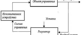
Industrial buildings, public institutions and residential buildings are equipped with complex air conditioning and ventilation networks. To organize the operation of a system that combines many technical devices, a ventilation control panel - SHCHUV - is used.
We will tell you how to assemble a shield that allows you to control the ventilation system and set the optimal mode for work or rest. The article we presented shows the components and describes the features of their connection. Taking our recommendations into account will help you competently automate the startup and shutdown of equipment.
Recommendations for assembling SHUV
Installation and testing of control panels should be carried out by specialists with appropriate qualifications; independently installing and connecting elements inside a switchboard or cabinet is not only not recommended, but also prohibited.
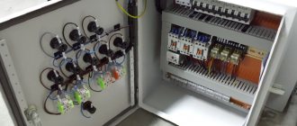
The housings are not made by hand, but purchased ready-made or ordered taking into account the specifics of the ventilation system. A set of devices is supplied with the case: switches, controllers, power supplies, switches, protection elements and wires.
It often happens that the set of instruments and parts is not fully equipped - there are not enough wires or circuit breakers. When selecting spare parts, it is necessary to maintain compliance with the technical characteristics (for example, the cross-section of wires or the current strength of the machine).
The set of SHCHUV elements is accompanied by a diagram according to which the assembly is carried out. Any deviations from the diagram may lead to improper operation or equipment breakdown.
Before ordering, you must make a list of all devices that are included in the ventilation system, as well as express your wishes regarding switching operating modes, the type of controller, and the presence of certain sensors. In some control panels, relays are installed instead of controllers.
An example of a ShchUV can be a sample with the following technical characteristics:
- nom. frequency – 50 Hz;
- voltage – 380 V;
- voltage of the connected fan – 220 V;
- engine power – 22 kW;
- protection level – IP65;
- dimensions – 400x800x180 mm;
- service life – 10 years.
Ready-made models are marked with symbols that contain information about the modification and its standard size, degree of protection, type of climatic modification, technical specifications or GOST number. In the latter case, manufacturers are guided by GOST 14254 and GOST 15150.
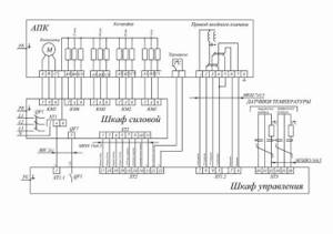
Device diagram
Connection of control cabinets is carried out according to the standard scheme and is regulated by GOST R51321-1. Cabinets, stands and panels are installed in corridors, control rooms or utility rooms. If technical conditions exist, ventilation and fire control units are located in one cabinet, which is located in the control room. This will provide quick access to emergency and operational ventilation control panels and allow you to quickly respond to problems in the system.
The rooms in which the panels are installed are subject to special requirements in terms of humidity and temperature. Devices must be reliably protected from direct ultraviolet rays, drops of water and dust. Magnetic vibrations and radio interference can also negatively affect the correct operation of devices, so their impact on devices should be limited. The temperature range at which operation of control cabinets is allowed is from -10 to +55 degrees. Installation of the device requires mandatory grounding, and the frequency of the mains current should not exceed 50 Hz. Electrical networks with voltages of 220 and 380 V are used as a power source.
The main requirements of the layout are that all control devices are located on one stand and in the same plane. The most important components responsible for the safety of the device must be equipped with light indicators and preferably connected to a personal computer. In addition, devices responsible for the correct operation of the main components must be equipped with two types of control: manual and automatic. The most convenient for use are cabinets equipped with a remote control, allowing a person who does not have much experience in controlling ventilation to control its operation. In addition, the device connection diagram should be simple and extremely easy to understand. This will help you turn off the installation yourself in case of an emergency, without waiting for repair services to arrive.
The main tasks of automation for ventilation
Since the modern market offers a large number of various technical devices for ventilation automation, the range of their functions is also extremely wide.
Main functions of the control module equipped with elements of electronic intelligence:
- Maintaining the specified parameters of the microclimate of the interior - air temperature and humidity, carbon dioxide saturation, etc.
- Possibility for the operator to remotely control the fans, turn them on and off remotely.
- Implementation of automated control over the sensors of all components and assemblies of ventilation equipment.
- Independent transfer of equipment to summer or winter mode.
- Monitoring the level of contamination of filter devices with the function of signaling the need for cleaning.
- Opening and closing air duct dampers, adjusting the performance of supply and exhaust fans.
- Cutting off the fresh air supply when the fire alarm is activated.
- Turning off the power supply in emergency situations - sudden surges or drops in voltage. This allows you to prevent failure of devices, sensors and individual components of the ventilation system.
Additional functions
Modern manufacturers, in order to fully satisfy customer requests, pay special attention not only to the reliability of the equipment they produce. An important factor in the competition for consumers is equipping products with as much additional functionality as possible.
Today, highly intelligent functions such as:
- Connecting ventilation to a single electronic “smart home” control controller.
- Manage settings via Internet applications, using Wi-Fi and Bluetooth.
Equipped with modern functionality, automatic equipment becomes clear and easy to operate, like other household appliances.
What is the ShchUV used for and where is it used?
Small household ventilation systems used in multi-storey buildings and the private sector do not require any additional devices. They are controlled remotely, using a remote control, or manually.
Unlike household ones, industrial systems have a much larger network length. Many functional devices, primarily fans, are initially installed in hard-to-reach places. Due to limited access, control is carried out using a unit equipped with a whole set of special equipment.
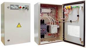
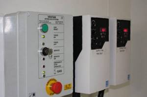
A modern ventilation control panel - SHCHUV is made in the form of a panel on which adjustment indicator devices are located, as well as in the form of metal cabinets fixed to the wall or installed on the floor. The internal space with the equipment located here is protected by hinged doors. To limit access to unauthorized persons, they are locked.
The main tasks that the ventilation control panel solves are as follows:
- Control over equipment, instruments and equipment included in ventilation systems.
- Protection of controlled devices in the event of emergencies caused by overheating, improper installation and connection, and short circuits.
- Regulatory functions – setting the required parameters for the performance and power of the equipment.
- The ability to program individual components and assemblies or the entire system for a certain period, from 1 day to 1 month.
- The control and adjustment processes of the ventilation control panel are greatly facilitated due to the installed indication.
- Each room can maintain its own temperature, which can be changed at the right time.
- Air filters, the degree of their contamination, as well as the condition of the internal walls of the air ducts are monitored.
- Control over the operation of seasonal equipment, which is subject to negative impacts due to sudden changes in outdoor temperature.
A ventilation system control panel installed on site allows you to constantly monitor work processes and the condition of all equipment while in one place. If some devices break down or stop, promptly detect them and fix them.
Which power actuators do not require integrity monitoring.
1. Intermediate relay.
Relays must consume minimal power and switch maximum voltage. That is, it is best to use an electronic relay.
In turn, the relay controls something.
There are 220V intermediate electronic relays, the operating current of which is up to 0.25A and therefore they can be controlled by switching power with low-current addressable relay modules “Rubezh”.
The intermediate relay PK-1P costs 680 rubles, switches 16A 220V and consumes 0.05A when 220V is activated.
This is what I understand as a relay amplifier!
2. Independent release.
The fire alarm energizes the release and the release switches off the circuit breaker.
But how can a fire alarm send a 220V signal to the release?
Using any relay capable of switching 220V.
But it is worth remembering that an independent release is a device that performs mechanical work and its current consumption is greater than that of the relay coils.
Here are the control signal parameters for the most common S2C-A independent releases.
We see that the operation current of S2C-A2 at 230V is 1A. That is, weak relays of low-current relay modules are not suitable for all.
It is tempting to control the low-current independent release S2C-A1, whose response voltage is 12..60V.
But the response current... for 12V is 2.2A. It is doubtful that the response current for 24V 4.5A is greater than for 12V, although it should be less.
Triggering such a release using the S2000-KPB will be on the verge of a foul, since the maximum switching current of the unit is 2.5A. Switching current “S2000-SP2 ISP.02” is 3A.
It is reassuring that the operating time of the release is 10ms.
An independent release is a good control method if additional attention is required to start a complex ventilation system: the ventilation system will not start simply after the alarm is removed. To turn on the system, you need to walk with your feet to the circuit breaker that is turned off by the release.
To turn on the system, you need to walk with your feet to the circuit breaker that is turned off by the release.
But there is one interesting point. Let me quote from the regulatory framework:
SP 60.13330.2012 Heating, ventilation and air conditioning. Updated version of SNiP 41-01-2003
12.3 For buildings and premises equipped with automatic fire extinguishing installations or automatic fire alarms, automatic blocking of electrical receivers of air heating, ventilation, air conditioning systems, autonomous and window air conditioners, fan coils, air-heat curtains and internal air conditioning units (hereinafter referred to as ventilation systems) should be provided. , as well as electrical receivers of smoke ventilation systems with these installations (or fire alarms) for:
a) shutting down ventilation systems in the event of a fire, except for the air supply systems to airlocks of premises of categories A and B, as well as to the machine rooms of elevators in buildings of categories A and B. Shutdown can be carried out:
centrally, stopping the power supply to the distribution boards of ventilation systems;
individually for each system.
When using equipment and automation equipment supplied complete with ventilation system equipment, shutdown of supply systems in case of fire should be done individually for each system while maintaining power supply to the frost protection circuits. If it is impossible to maintain power to the frost protection circuits, it is permissible to turn off only the fan by sending a signal from the fire alarm system to the remote control circuit of the supply system fan. When organizing a shutdown in case of fire using a circuit breaker with an independent release, the signal transmission line must be checked for shutdown.
The highlighted phrase about checking the signal transmission line contains a big problem. The independent release will most likely be 220V! And we have the problem of continuous monitoring of the integrity of the 220V control circuit.
3. Contactor (starter).
The dry contacts of the relay open the self-retaining circuit of the magnetic starter.
The advantage of this approach is that when relieving an alarm, you don’t have to go to the control panels.
So, for example, it makes sense to control the fire-retarding valves of the OZK: the alarm was removed - the OZK opened on its own.
The current on the PME 211 coil is only 0.1A. But still, the use of a low-current addressable relay module for some addressable systems is questionable, since this is a continuous current.
Types of supply and exhaust systems
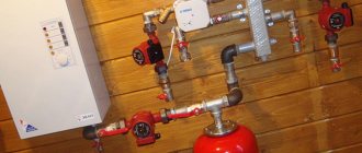
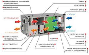
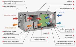
The most effective ventilation systems are supply and exhaust systems that include recuperators in the design. These devices are heat exchangers that use the energy of exhaust air. In this case, the inlet flow and outlet do not come into direct contact. The recuperator can be rotary, plate or containing an intermediate coolant. The rotary one is highly efficient, but is considered the most expensive. Its use is uneconomical when the outside air temperature during the cold period does not fall below 15 degrees below zero. At the same time, air handling units with rotary heat exchangers, used in northern latitudes, provide double savings in energy costs for heating premises. The plate version of the device is more affordable and belongs to the budget segment.
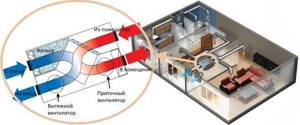
Installation with recuperator
During the cold season, the incoming air flow heats up the room and, when leaving, gives off heat to the newly incoming flow. The absence of mixing guarantees a constant flow of fresh, clean air and removal of waste air. In summer, when it's hot, the device works in reverse. The warm flow, entering the room, is cooled, and when leaving, it takes away heat from the newly entering one.
General circulation ventilation is a cheaper type. The air coming from outside receives heat by directly contacting the exhaust air.
In this case, the cleanliness of the air in the room can no longer be the same as in the above-described option. Circulation systems cannot be installed in buildings where the atmosphere may contain carbon and flammable gases, toxic substances and other components hazardous to life and health.
Another disadvantage of forced circulation ventilation is its ineffectiveness when the outside temperature drops below zero.
The most expensive options for air handling units with forced ventilation are systems equipped with air conditioners. The devices allow you to regulate the temperature in the room within a wide range and provide comfortable conditions all year round. The system is equipped with a heat pump and a filtration circuit necessary for air purification.
Each of the forced ventilation is provided with a control system. The most expensive options are equipped with sensors and “smart” electronics capable of adjusting modes independently, according to a predetermined program.
For ventilation of buildings, especially multi-storey buildings, not only mechanical air circulation can be used. The pressure difference inside and outside the room can create the flow necessary for ventilation. The device of supply and exhaust ventilation with natural circulation is based precisely on this principle. The following nuances are taken into account:
- To place the air intake, the side of the building that is most often blown by winds is usually selected.
- The withdrawal is made from the opposite side
- The air intake itself is equipped with a deflector that enhances the incoming flow.
This system is characterized by its simple design and low cost. However, simplicity excludes the possibility of saving heat and many of the advantages provided by installations with a forced type of ventilation: ionization, cleaning, humidity control.
Automation of ventilation systems
Modern ventilation control systems allow not only to control the volume and speed of air entering the room. They can serve not only for ventilation work - the advantage of modern ventilation mechanisms is the ability to create the necessary microclimate and regulate all air parameters.
However, the more complex the mechanism, the more effort must be made to regulate its operation. For this purpose, automatic control systems are increasingly being installed in premises, making it possible to significantly simplify the task of regulating ventilation and air conditioning systems.
Automation functions and capabilities
The automation of the ventilation system performs several important tasks. Let's get to know them.
- Thanks to automation, the entire system works properly and is always under control. Usually a special accident analyzer is installed. Modern developments make it possible to control automatic systems remotely - the operator only monitors the operation of the existing device, and can also make his own adjustments by setting certain modes.
- Using automatic equipment, it is possible to analyze individually and monitor the functioning of each existing mechanism. In addition, it is possible to monitor the overall activity of the ventilation circuit. The unit’s sensors provide certain data, the automatic system examines the position and makes its own adjustments to the operation of the equipment. If an accident occurs, a corresponding shutdown signal is sent to a special start button.
- Automation in ventilation systems is also designed to save valves and water heating circuits from the harmful effects of low temperature values. In addition, automatic equipment prevents the temperature from dropping to dangerous levels.
- The automatic control system allows you to regulate the ventilation in the room. Thanks to this addition, it is possible to switch various modes. Thus, in conditions of sudden changes in loads and temperatures, automation can reduce the rotation speed of existing fans, as well as deactivate the equipment completely.
- If there is such a nuisance as a short circuit or other similar problems, then the automation simply blocks certain mechanisms to prevent fire and electric shock to people.
As you can see, the automation that comes with the ventilation system performs many functions and allows you to avoid many serious problems. In addition, it is much easier to regulate ventilation with automatic components.
Main elements of the ventilation control system
Modern control systems for ventilation and other communications are a technically quite complex device based on microprocessor technology and a whole complex of control and actuating mechanisms. The following devices are considered the main elements.
Sensors
Designed to control various parameters of the ventilation network. The ventilation control panel circuitry ensures the reception and processing of information from many similar devices (digital or analog). Based on the information received from the sensors, commands are generated for the actuators.
Based on their location, the following types of sensors can be distinguished (designed to monitor atmospheric parameters):
- Room sensors are installed indoors and allow you to monitor the state of the atmosphere inside the building, which is necessary to select the most optimal ventilation mode.
- Atmospheric sensors are mounted outside buildings, thanks to them it is possible to select the ventilation operating mode when weather conditions change (for example, when the ambient temperature decreases, the performance of heating devices increases, which allows you to change the ventilation mode in advance).
It is also possible to divide the sensor according to the place of direct installation (sensors that control the operation of ventilation devices and air flow parameters):
Duct sensors are mounted inside air ducts. Thanks to them, it became possible to obtain information about the speed of the ventilation flow, the pressure and pressure created by the fan, as well as other flow characteristics.
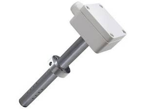
Sensors of this type can be installed directly on the walls of air ducts or in a section across the direction of air flow.
External sensors are mounted mainly on fan installations; they allow monitoring their operating parameters (impeller rotation speed, winding temperature, brush condition and other parameters).
In practice, the following elements are most often used:
- Temperature sensors, which can be analog or digital. They are installed not only to control air temperature, but also to determine the thermal operating conditions of various devices.
- Humidity sensors allow you to obtain data to select a ventilation operating mode that provides a more comfortable atmosphere in the room.
- Speed and pressure sensors are designed to determine the operating parameters of fans and control (switching) devices; based on the information received from these devices, the operating modes of the equipment change.
All sensors must be installed in accordance with design requirements, taking into account manufacturers' recommendations.
Controllers
Devices designed to receive and process signals coming from sensors. Based on them, commands are generated for various actuators, which make it possible to change the operating mode of ventilation devices.
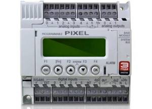
The most in demand are devices based on microprocessor technology, which are compact in size, multi-functional and can be mounted in standard control cabinets. The Pixel controller for control panels is quite popular (can be used to control heating, water supply and other communication lines).
Actuators
Various mechanisms that ensure the operation of the system. These include fans, various flow direction switches, valves, heating and air conditioning devices. Can be powered by electrical, pneumatic or hydraulic power sources. They come into operation when control commands are received from the controller.
Features of the SHCHUV device
Installation and configuration of control panels is carried out according to the rules and regulations dictated by government documents, such as GOST R 51321.1. Cabinets for pumps and electrics, panels for ventilation and air conditioning systems are mounted in corridors, utility rooms or in specially designated rooms - switchboards.
If the building has the capabilities, then all control units, including ventilation and fire protection, are installed in control rooms.
In the room where the switchboard is located, room temperature and normal humidity levels must be maintained. All devices must be protected from direct UV rays and dust, as well as from magnetic vibrations and radio interference
Manufacturers of electrical equipment offer a variety of configurations that vary in size, functionality, degree of protection and level of programming. The simplest modifications are intended for servicing private residential real estate, while complex modifications are intended for enterprises and public buildings.
Requirements for the configuration of control panels
When choosing a SHUV, they are guided by the size of the working area, the ability to install the necessary devices, ergonomics and safety. The last point applies both to the installers themselves, who regularly service the networks, and to people who may be nearby.
The main requirements for SHUV and SHUV are as follows:
- the panel must accommodate all control devices for the ventilation and air conditioning system;
- important components must be equipped with an indication, light, digital or connected to a PC;
- devices responsible for the most important equipment must have dual control - automatic and manual.
All devices are neatly placed on the same plane. The package should be as simple and easy to understand as possible. If the ventilation panel is assembled according to all the rules, then, if necessary, even a person ignorant of electricity will be able to turn off emergency devices.
Modern control units are manufactured taking into account the possibility of saving energy. Let’s assume that properly selected automatic devices can reduce costs by 50-65%
The content and functionality of the shields may vary. For example, some systems require a frequency converter, while others do without it. The most convenient for use are cabinets and panels with automation and remote controls.
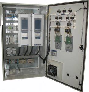
Work Item Overview
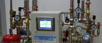
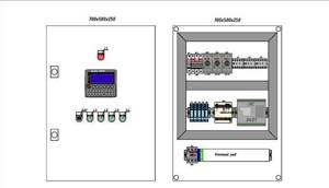
Structurally, the SHUV is a rectangular plastic or metal case with the required protection class IP 45. If operating conditions are associated with an increased risk, then the protection class is higher.
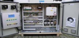
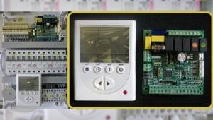
Inside the case there are devices such as a power supply, controller, and converters. Several circuit breakers are responsible for individual devices: air heaters, recuperators, fans, cooling units, etc.
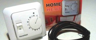
A mandatory element is a manual control panel. An alarm unit is also required, which is triggered in an emergency and produces warnings with light or sound signals.
Strips and terminal blocks for installing electrical devices and connecting them with wires look the same as analogues for electrical distribution boards
Control elements also include sensors. These are a kind of receptors that collect various information about the state of the system and its environment.
They measure the temperature of the air and the devices themselves, the degree of concentration of gases or contamination of system elements, measure the speed of air movement, etc. The data obtained is sent to automatic regulators, and the operation of the system elements is adjusted.
Based on their functions, sensors are divided into the following types:
- temperature;
- humidity;
- speed;
- pressure, etc.
Temperatures can be either digital or analogue. A signal about a sharp increase or decrease in indoor temperature may cause the system to switch to another mode.
Humidity sensors operate on the same principle. The movement of air masses inside ventilation ducts can be determined using speed and pressure sensors. Based on their installation location, sensors are divided into internal and external. The first ones take data indoors, the second ones, which are also called atmospheric or street data, take data from outside buildings.
Ventilation sensors can also be ducted, that is, installed inside air ducts: either on the walls or across the air flow. They are universal and can transmit a large amount of information: temperature, pressure, air speed
Some sensors are fixed on the surface of parts that need to be monitored. They take parameters of the devices themselves, for example, winding temperature, rotation speed, etc.
The installation of sensors requires careful selection. On the one hand, the more information, the more accurately the system operates, but on the other hand, the operation and maintenance of the network becomes costly in terms of energy consumption.
Controllers work in conjunction with sensors. These are the devices that receive information and process it automatically. They can be called intermediaries, since the signal is then transmitted to actuators: air flow switches, fans, refrigeration units, heaters.
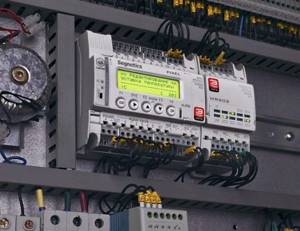
Controllers with microprocessors are more suitable for installation inside SHUV. They are compact in size and do not require a large area for installation
Particularly popular are universal type controllers, which are capable of simultaneously processing information coming from various systems: ventilation, heating, etc.
Advice from professionals
The efficiency and trouble-free operation of a ventilation unit or hood largely depend on the correct choice of control cabinet
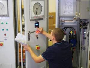
Therefore, it is better to entrust the purchase of such an important and technically complex unit to professionals. Before purchasing a cabinet, the master will carry out full monitoring of all components of the ventilation system and decide on the contents of the cabinet
After selecting the configuration, the specialist will test the installation and determine the maximum possible load on a particular device and on the network as a whole. Based on the data received, the wizard will select the optimal connection diagram, determine the operating mode of all devices in order to increase their efficiency, and only after that will specifically indicate the necessary equipment.
When choosing equipment yourself, you need to focus on the current strength in the circuit, the power of the units and the size of the wire cross-section. This is due to the fact that if the wire and current strength do not match, severe overheating of the terminals and contacts occurs, which can lead to breakdown and even fire of the equipment. When purchasing and connecting a cabinet yourself, you need to remember that for each square millimeter of copper wire there should not be more than 10 amperes, and connecting terminals, one of which is made of copper and the other of aluminum, is unacceptable. This can lead to a galvanic effect and weaken the contact.
To learn how to install a simple ventilation control cabinet, see the following video.
How to arrange ventilation in a wardrobe: basic rules
The ventilation system can be natural (the simplest, but also ineffective) and forced (the most effective, but costly and more complex to organize).
The design of the ventilation system itself depends on where exactly the dressing room is located, and whether it has a window:
A separate room with a window (no matter what size). A separate room without a window, through the wall is the street. A separate room without a window, with other rooms on all sides. Large wardrobe (furniture partition from floor to ceiling).
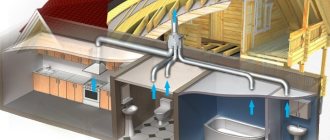
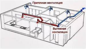
The system is made so that there is both an influx (intake of fresh air) and an exhaust (removal so that it does not stagnate), that is, full circulation.
Below we will briefly look at ways of arranging ventilation systems for rooms with different locations.
If there is a window
If there is a window, the task is simplified; in some cases, you can even do nothing at all, or do the minimum.
In this case, the flow of fresh air is organized through the window: you can either keep it slightly open, or put a window valve in it (in this case it will not need to be opened). Air removal will be carried out through other rooms. The most important nuance in this case: there must be a free flow from a closed wardrobe (after all, they are usually closed). That is, there must be either a gap under the door or a grille in the door leaf.
If there is no window
Above we mentioned 2 different situations for wardrobes without windows: either there is a street through the wall, or the room is located in the depths of the apartment, and is surrounded on all sides by other rooms.
Ventilation diagram in the dressing room
If there is a street behind the wall, then the problem can be solved in the following ways:
- Install a supply valve into the wall, and air will be removed through other rooms. The option is simple and cheap, suitable for small spaces (conditionally up to 5-15 m²).
- Place a supply fan in the wall, and the removal will take place through other rooms. The option is a little more complicated and expensive (you will need to buy a fan and connect it to the mains). It is relevant when the area of the room is large enough, and/or quite expensive things are stored in it, and/or there are a lot of them. It is also worth installing a fan if the microclimate in the apartment is not ideal: there is humidity, there have been problems with mold.
- Place an exhaust fan in the wall, and the inflow will be through the room into which the wardrobe door opens (or from the corridor). This option is good because it will partially reduce the load on the main hood (ventilation shaft or hood in the kitchen/bathroom), since it will remove air not only from the dressing room, but also from the living room nearby.
If there is no street behind the wall, then the problem can be solved in the following ways:
- If air ducts are installed throughout the apartment, then separate supply and exhaust lines (or just one) are also connected to the dressing room. Relevant at the construction and finishing stage. After the renovation is completed, such work will be more difficult and expensive to carry out (since you will have to first disassemble it and then refinish it).
- If there is a living room on one side and a kitchen/bathroom on the other side, then you can make holes in these walls and cover them with bars. In this case, air will enter the wardrobe from the living space and be removed through the kitchen.
- If there are living quarters on both sides: a hole is made in the wall between one of them (or both) and the wardrobe and covered with a grill. Through it, air will flow in and be removed through a ventilation shaft or hood (in the kitchen/bathroom). The flow is realized through a gap under the door or a flow valve in the door leaf.
If it's a wardrobe
In addition to a separate room for storing things, a spacious wardrobe can also be used. For him, the ventilation system is organized somewhat differently. The options are:
- We make slits in the closet: several on the doors below and several in the wall, right under the ceiling. The upper slots should be made closer to the back wall. There is only one rule here: the more holes, the better the air exchange will be in the end.
- If there is a kitchen or bathroom behind the closet wall, then we make a hole in this wall, and make slits in the closet door. Through the slots from the bedroom, air will flow into the closet, and will be removed through the hole into the kitchen.
Ultimately, which option to choose depends on the layout of the premises and the size of the cabinet.
Click “Like” and receive only the best posts on Facebook ↓
Which power devices require circuit integrity monitoring.
All the cases discussed above are when the power circuits are not directly controlled: everything after the relay contacts is unknown.
But it happens when power actuators must operate during a fire, so the power circuits for their activation must be controlled - fortunately, there are few such devices.
Power actuators requiring circuit integrity monitoring:
1) reversible smoke exhaust and air pressure valves;
2) engines of fire pumps, valves and fans;
3 power electromagnetic (solenoid) fire extinguishing valves;
4) control cabinets for curtains or transoms.
Fire fan control cabinets that comply with regulations.
These cabinets have everything you need to meet the standards:
1. The cabinets have the ability to start with a voltage of 24V, which eliminates problems with integrity monitoring.
2. Have manual/automatic operating modes
3. The cabinets provide comprehensive dispatch signals: Operation, Automation, Emergency.
4. All circuits, including power ones, are monitored.
5. There is the possibility of external manual control and control from the cabinet panel.
6. And most importantly, a certificate of compliance with federal law No. FZ-123.
Bolide.
ShKP-10 14925₽.
Control and launch cabinet. There are no valve control circuits and it is necessary to use the S2000-SP4 smoke removal module, costing 2200 rubles, within the addressable system.
Plasma-T.
SHUV 11kW 15332₽.
Control cabinet for three-phase pump/fan motor with power up to 11 kW with direct start, complete set DEK, IP31. There are no valve control circuits - something needs to be done too.
Frontier.
SHUN/V-15-00 prot.R3 29000₽.
Comparing this cabinet with others is not entirely correct, since this cabinet itself is an addressable device, that is, only one wire of the address communication line needs to be connected to it and there is no need for a device or module for control loops and start lines.
Management and dispatching occurs via an addressable network.
There are no valve control circuits and it is necessary to use the MDU-1 smoke removal module within the addressable system, costing 2280 rubles.
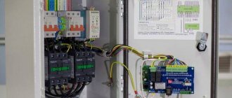
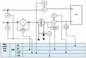
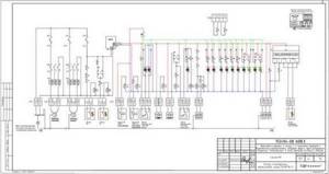
Ventilation control cabinet diagram
diagram of the control unit for supply ventilation with water heating
The standard layout of the ventilation control cabinet includes:
- frequency converter;
- microprocessor controller;
- starters, switches;
- circuit breakers;
- contactors;
- defense mechanisms;
- relay;
- light indicators of modes.
diagram of the control unit for supply and exhaust ventilation with water heating
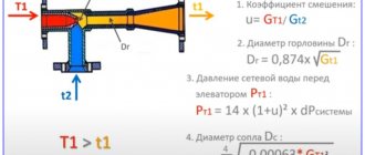
Frequency converters are necessary to change the rotation speed of fan blades and asynchronous motors; they start mechanisms without jerking, providing a more favorable operating mode. Frequency adjustment provides speed control in both manual and automatic modes and prevents engine overload. Reducing energy costs and increasing system safety, extending service life.
One of the important elements of the ventilation cabinet control circuit is the controller.
Controller types:
- discrete;
- analog.
Models presented on the Russian market contain a programming menu in Russian. The controller's capabilities are sufficient to solve any problems that arise during the operation of ventilation systems. The most practical are freely programmable controllers, which allow you to organize control of a ventilation system of any design.
The reliable and simple design of the ventilation control cabinet allows you to avoid its service and maintenance. Once every 6 months, the integrity of the cables and insulation and the grounding condition are checked. In addition, you must adhere to the rules for operating the equipment.
Purpose and configuration of the pump control cabinet
The technical content of different models differs, since control points have an individual functional focus.
Brief description of standard equipment
The presence of certain elements depends on the number and category of pumps, narrow or broader technical capabilities, and the presence of additional functions.
The basic equipment for most of the models offered for sale is as follows:
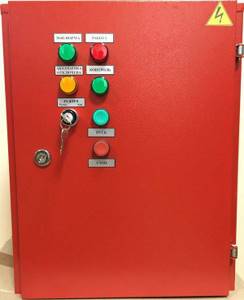
- Rectangular metal case with a control panel located on the front side. The design of the panel may differ, but it must have indicators and buttons such as “Start” or “Stop”.
- A switch (one or more) that allows you to turn the pump on/off manually.
- Fuses and protection elements.
- Control unit that regulates the voltage of three phases.
- Frequency converter required to control an asynchronous motor.
- An automatic control unit responsible for scheduled and emergency shutdown of equipment.
- A set of sensors showing water pressure and temperature.
- Thermal relay.
- A set of light bulbs – light signaling.
The main functions included in the control unit depend on several factors. For example, if there are 2 pumps, the main and additional (backup), a program is installed that allows you to turn on both mechanisms alternately.
Control panel for two pumps operating in standby mode. The advantage of interval switching is uniform load distribution and an increase in the planned resource.
The temperature sensor protects the equipment from overheating and operation in dry running mode (the likelihood of such a situation often occurs in wells with insufficient flow). The automation stops the operation of the equipment, and when favorable conditions for water intake occur, it turns on the motor of the connected pump again.
- The pumping equipment control station will reduce energy consumption and guarantee an extended service life
- A control cabinet for one or more (up to 9) submersible pumps automatically starts them when water is drawn from the system and the pressure in it decreases
- The submersible pump is equipped with a relay-type fuse to prevent short circuits and emergency situations from affecting the equipment.
- The pump control station can be powered from a centralized network or from an autonomous electric generator
Protection devices against voltage surges, phase failures, and incorrect connections protect mechanisms and prevent them from operating in emergency mode. They adjust the network parameters, and only after the parameters are equalized, they automatically connect the equipment.
Overload protection functions in much the same way. For example, there is a ban on simultaneous activation of two pumps, which leads to unnecessary costs and irrational use of equipment.
Benefits of professional installation
According to the rules, the installation and maintenance of ventilation systems, as well as control units, must be carried out by specialists with an engineering education. They bear full responsibility for incorrect selection, installation, connection of devices, as well as for maintaining technical devices in improper or unsafe condition.
To correctly determine the contents of a panel or cabinet, installers do a full monitoring of the ventilation network. Then you need to do the following:
- analyze the load;
- choose the optimal scheme;
- determine the operating modes of devices in order to increase efficiency;
- select equipment.
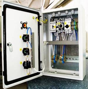
The assembly itself takes a little time: all the devices are mounted one by one in several rows, the wires are carefully connected to the terminal blocks and laid along the lines in organized bundles, then taken out.
One of the connection options, where NK1 and NK2 are duct-type heating devices; M1 – 3-phase fan; A, B, C – network connection, N – neutral, PE – ground; Q – protective thermostat against overheating; Y – ignition protection thermostat
Professional installers have experience installing and operating control panels, so they are unlikely to make a mistake with the choice of model and the nuances of connecting devices. In addition, they are well versed in diagrams and can quickly identify if there is an error in a drawing.
If you don’t figure it out in time and connect the devices according to an illiterate diagram - and this also happens - you can create an emergency situation.
The sale and distribution of panels and cabinets is carried out by many companies that produce or sell ventilation, refrigeration and heating equipment. For example, in Moscow this can be done in, “Roven”, “AV-automatics”, “Galvent”, etc.
Automation boards
The operation of the automated system, its convenience, reliability and safety of operation directly depend on the process control algorithms (specialists who performed the design and commissioning), as well as on the capabilities of the components. Algorithms are implemented at the software level and “hardwired” into freely programmable controllers installed in automation panels .
When connecting sensors to the automation panel, the type of signal transmitted by the converter (analog, discrete or threshold) is taken into account. Expansion modules that control device drives are selected in the same way.
Ventilation system panels can be power, control or combined if the system is small. Automation panels for ventilation provide:
- Turning the ventilation system on and off;
- Equipment status indication;
- Protection against incorrect connection of supply voltage and short circuit;
- Ventilation unit performance control;
- Indication of the status of air filters;
- Protection against overheating of electric motors;
- Protection of the air heater from freezing;
- Maintaining and controlling the air temperature at the inlet of the ventilation unit and in the room;
- Possibility of using temporary manual control algorithms.
Defense system
Automatic air ventilation control, like any other, has no right to exist without ensuring proper safety. The protective mechanisms in the shield can be triggered if one of the following circumstances occurs:
- Failure in the operating mode of the component element.
- Failure of any instrument or device.
- Inability to control certain air parameters in the room - if communication with some sensor is lost.
To solve these problems in the operation of an automatic ventilation mechanism, a control controller is designed. The use of controllers allows you to quickly respond to the most minor deviations from the normal state during the operation of each device and, at the same time, promptly eliminate them.
Thus, controlling the ventilation of a room, if you have a special panel, becomes fast, simple, as convenient and safe as possible.
Operating principle of automated ventilation systems
So what is the basic operating principle of automated ventilation devices?
Like many modern technologies of this kind, this one is aimed at minimal operator participation in the process of controlling air freshening processes. In the literal sense of the word, the devices themselves calmly cope with the tasks.
Smart operating systems allow you to develop an algorithm specific to your premises or premises, according to which at a certain time of day the system will operate in a special mode. Organizing this system with your own hands is not easy, but with some effort you will succeed.
For example, at lunchtime the sun shines brightly directly on the back side of the building, where it usually does not reach during the day. This means that at this moment the exhaust unit system in this part should work harder.
But, since most of the day this side is not exposed to sunlight, leaving the ventilation units running strongly all day is not economical.
But there is also no way to completely distance yourself from the problem. This means that the system itself must control the situation and switch the level of ventilation depending on the conditions and situation.
In this case, the computer will be helped by a whole bunch of sensors that determine the main air parameters. By transmitting data to the system control center, they trigger an almost instant decision-making process by artificial intelligence.
The fans will speed up, the inlet valves will open wider, and the temperature will drop below the desired average. But only for the right time!
Afterwards, all sensors will transmit new measurements, which will indicate normal temperature conditions. The operation of the ventilation shafts will return to normal.
Ventilation system switch
That is, in addition to the initial functions of competently providing fresh air to the room, the system acts as a saving device that will allow you not to waste electricity. to menu
The most important thing is quality!
When choosing any devices or complete automation systems for exhaust and intake ventilation, you should pay attention to their power consumption. Some devices, despite being good, are extremely uneconomical (especially when working with exhaust) and will seriously bite your wallet due to electricity tariffs
Especially from this perspective, the automatic supply ventilation will be captivating.
Some devices, despite being good, are extremely uneconomical (especially when working with exhaust) and will seriously bite your wallet due to electricity tariffs. Especially from this perspective, the automatic supply ventilation system will attract attention.
The country of origin also plays a role. The exhaust ventilation circuit is quite complex and you should only work with it when purchasing devices from good manufacturers.
Ventilation system panel
European manufacturers are considered to be of the highest quality, as they honor their reputation and do their work carefully. Chinese appliances are no less high quality, but energy-intensive. This means they may not always suit you.
The importance of the quality of the automated part of your ventilation helps office workers cope better with the summer heat. In turn, this increases productivity and activity.
And ventilation systems do not have such a detrimental effect on your health as other cooling devices. to menu
Why is it needed and what functions does the cabinet perform?
The main purpose of distribution cabinets is to control the electric motor of one or several pumping units at once. In this case, the type of pump does not matter. This can be submersible equipment or a well or drainage pump.
Moreover, the purpose of pumping equipment may be different. For example, a submersible type unit is needed for the efficient operation of a heating system, arranging the water supply of a country house, or creating a fire extinguishing system. But the drainage pump, together with the control cabinet, is useful for pumping liquid.
If you install a control cabinet to coordinate the operation of the well pump, you will finally find long-awaited peace and relaxation, since from now on you do not need to monitor the operation of the equipment, all this will be done by the automation located in the cabinet. In this case, this device will be able to perform the following functions:
the equipment will ensure safe and smooth starting of the pump unit engine; automation will be able to regulate the operation of the frequency converter; in addition, the device will monitor the pressure in the system, the water level, as well as its temperature, which is very important for the timely switching on and off of pumping equipment.
The functions of control cabinets for two or more pumps are even more extensive:
- if the unit notices that one of the pumps is operating in emergency mode, it will immediately connect the second pump to operation;
- since the automation of the control cabinet will regulate the alternating operation of each pump, the overall wear and tear of the pumping units will occur later;
- if one of the pumps is left idle for a long time, the equipment will be able to protect it from silting;
- Thanks to this device, you can manually block the operation of one of the pumps;
- cabinet automation has different programs for controlling several pumps;
- if necessary, you can obtain complete data on the operation of each unit separately.
Control cabinets with ATS (automatic transfer switch)
Purpose of AVR
The automatic transfer switch is designed to provide power to the load from two independent sources: it controls power circuit breakers that protect two independent inputs and supply current to the busbar. ATS can also be used to automatically turn on backup equipment when identical main equipment is turned off. The use of automatic transfer switches allows you to avoid equipment downtime, disruptions in technological processes that arise as a result of a network failure or if its main characteristics are outside the permissible values.
Application area
AVR is used: in uninterruptible power supply systems and devices; to provide power to loads of particular importance; in systems of parallel redundancy of power supplies.
Main functions of ATS
The main function is automatic switching to a backup power source when the voltage of the main source disappears or its parameters go beyond normal values.
- Motorized shifting;
- Built-in control relay;
- Dual power supply;
- Switching under load;
- Manual emergency switching, setting range 5-15s.
- Control of increase or decrease in voltage and frequency;
- Accounting and monitoring of electrical energy of the output voltage of the automatic transfer switch.
Description of ATS operating modes
The AVR can operate in automatic and manual mode.
Automatic operation:
Restores power to consumers when the main power source is turned off by connecting a backup power source. In the event of a loss of voltage at the main source, the machine will turn off the circuit breaker of the main source and turn off this source after the time set by the timer. After the delay time set by the timer has expired, the automatic switch of the backup source will turn on. When power is restored to the main source, the timer will, after a set time, turn off the backup source circuit breaker and reconnect the main power source using the circuit breaker. To control the automatic transfer switch, a programmable control relay is used, in which all the operating logic of the ATS circuit is programmed. The programmable control relay is equipped with a liquid crystal display, which displays information (in the form of display texts in Russian) about the current state, switching and emergency situations in the power supply circuit, has a non-volatile memory, so even if the auxiliary power supply of the ATS circuit is completely de-energized, the program is saved even when When power is restored, the circuit continues to operate based on the current state of the power supply circuit.
Manual operation:
When the ATS operating mode switch is switched to the “MANUAL” position, only the output control commands of the programmable control relay are turned off, all alarms in the form of display text messages continue to work. Control of circuit breakers: input 1 (QF1) and input 2 (QF2) is carried out using buttons on the front panel of the ATS cabinet.
ATS circuit with two inputs (working and backup) and one output.
Automatic reserve entry can be made with different operating algorithms at the customer’s choice:
ATS with first input priority:
In normal mode, power is supplied only from the first input. If the voltage on it disappears, the machine switches to the second input; when supply is restored at the first input, the ATS board immediately returns power to it.
ATS with equivalent inputs:
Capable of working for a long time from both the first and second input. When the voltage is turned off at the first input, the second input is automatically connected, from which the voltage continues to be supplied. There is no provision for automatic return to the first input when power supply is restored; this occurs only when power is lost at the second input. In ATS cabinets of this type, it is possible to manually switch from one input to another.
AVR without return:
When the power supply to the first input is interrupted, an ATS of this type automatically switches to the second input. Returning to the first entry is only possible in manual mode.
Some automatic transfer switches provide for independent operation of each input for different groups of consumers. If one input fails, all consumers are connected to the serviceable input.
Kinds
A typical/standard control cabinet for smoke removal fans, supplying outside air, contains a control unit for starting 1 to 4 exhaust fans for removing flue gases or supply air boost fans.
Therefore, for the normal functioning of a smoke protection installation, it is necessary to include in the design diagram at least two cabinets for controlling smoke removal fans and supplying clean outside air, and commands to operate fire dampers must be supplied from alarm system devices and fire extinguishing installations.
Multifunctional, as well as non-standard smoke protection control cabinets/panels, ordered according to developed designs for smoke removal and air pressurization systems for large public and industrial construction sites, in addition to the standard set of the above equipment, contain in the product housings additional control units, starting actuators, and electric drives:
- Fire-retarding valves installed on the air ducts of general ventilation of the protected object.
- Smoke removal valves, which are receiving devices for volatile, gaseous products of the combustion process before transportation through fire-resistant boxes and shafts for release into the atmosphere.
- Fireproof transoms.
- Anti-aircraft lights, smoke exhaust hatches.
Types of smoke protection control cabinets at the installation site:
- In fire stations, control rooms, security rooms, centralized surveillance control rooms, where security system equipment is installed.
- In rooms located outside fire compartments of the protection facility served by smoke removal systems.
Clarifications:
Smoke ventilation cabinet - when control is carried out from a multifunctional cabinet not only for smoke removal, but also for air pressure and fire dampers.
But, if the cabinet controls only 1 smoke exhaust fan, 1 fire suppression valve - this is the smoke exhaust control cabinet.
Manufacturers do not name their products as soon as they are:
- smoke control cabinets;
- cabinets/blocks/smoke ventilation control devices;
- fire automatic smoke removal cabinets, etc.
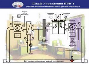
Control cabinet for smoke removal or air supply fan SHUV-1
Choosing a location
The cabinet and panel of automation and control of ventilation systems are connected according to standard circuits, which are determined by GOST R51321-1. To install this equipment, switchboard rooms are used, and in their absence, corridors and utility rooms.
If technical conditions allow, installation of ventilation and fire control units is carried out in a common cabinet. It is located in the control room, which allows quick access to smoke ventilation control equipment and prompt action in case of accidents and system malfunctions.
Rules for placing panels and cabinets:
- Compliance with the established temperature regime is of great importance for the stable operation of the panels. A certain interval has been established - from minus 10 to plus 55 degrees. Exceeding the limits can lead to failures and disruptions in the operation of the system.
- All equipment and equipment that ensures the operation of ventilation systems is placed inside a metal or plastic shield. The degree of internal protection must be at least IP45. This protection prevents small solid objects and water from getting inside.
- The device operates at a voltage in the range of 220-380 V and a current frequency of 50 Hz.
- Installation of control panels is carried out in rooms with normal air humidity. There should be no sources of dust or heat, and exposure to any aggressive substances is excluded.
- To install cabinets and panels, it is prohibited to use places with radio interference, magnetic and radiation radiation, or direct exposure to sunlight. Violation of this rule may lead to incorrect operation of the devices. Upon completion of the installation work, when the entire assembly is completed, a grounding system must be installed.
Conclusions and useful video on the topic
What the SHUV looks like when assembled, what is included in the “filling”, how the devices are mounted and the wires are connected, can be seen in the videos below.
Step-by-step assembly and installation options:
Video review - sample assembly of SHUV with heater:
Automation of a ventilation or any other system is a responsible and expensive process. If the equipment is selected or assembled incorrectly, an accident may occur resulting in people being injured, for example, at a chemical plant.
At a minimum, equipment, also expensive, will fail. For these reasons, the installation of control units from the initial design stage to the end should be carried out exclusively by specialists.
Please write comments in the block below. Share information that may be useful to site visitors. Ask questions, tell us about how you installed the ventilation system control panel with your own hands, and post photos related to the topic of the article.
Why is supply ventilation needed?
Insufficient air exchange in the house is fraught with consequences:
- with a lack of oxygen, the functioning of the central nervous and cardiovascular systems is disrupted;
- performance decreases;
- indoor humidity increases;
- the concentration of harmful substances in the air increases;
- the development of fungus and other pathogenic microorganisms occurs.
In our opinion, there are more than enough reasons to think about it.
Calculation of ventilation in a private house
It is worth noting that, despite the apparent simplicity of the operation of ventilation systems, it is better to entrust the calculation of supply ventilation to a professional who will not only select the optimal monoblock or design a stacked system, but will also receive project approval from the fire services.
What to consider if you decide to do the calculation yourself:
- determine the purpose of the premises - residential (apartment, private house, dacha) or non-residential (commercial, industrial), total area, number and type of activities of people occupying it at the same time, and also take into account the level of humidity in the room;
- calculate the required air exchange (for residential premises it is 3 cubic meters per hour per 1 square meter). Air exchange for other rooms is given in the table (compiled in accordance with SNiP 2.04.05-91 standards);
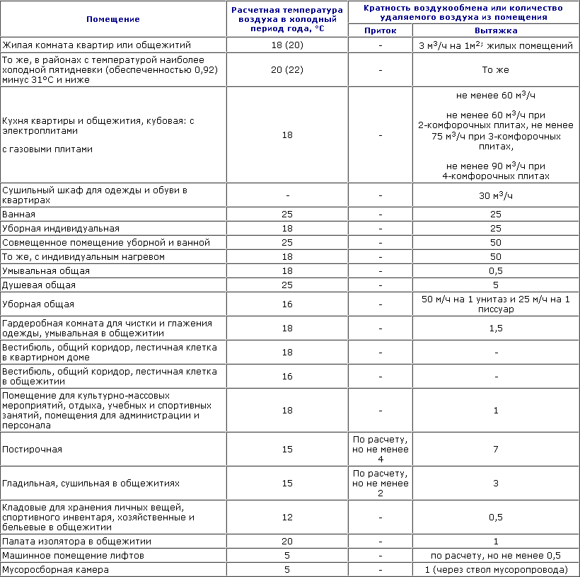
Calculation of air exchange (table - air exchange rate, amount of air removed from the room)
- develop a diagram that will serve as the basis for calculating the cross-section of air ducts;
- make a drawing that will contain the diagram and all calculations;
- approve the drawing with the relevant government agencies;
- install the ventilation system.
The slightest error in calculations will lead to a decrease in the efficiency of the ventilation system or an increase in energy costs.
Supply ventilation in the apartment
Most apartments are not equipped with fresh air ventilation systems. The air enters them from open vents. Considering the conditions in which the residents of the metropolis live, the issue of obtaining clean air is more than acute. Consequently, they are more interested in installing such systems than others.
The requirements for the ventilation system in the apartment are:
- compactness;
- the ability to reduce noise levels;
- increased requirements for air purification;
- nice design or the ability to install the system behind the ceiling or outside wall.