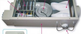
Accessories
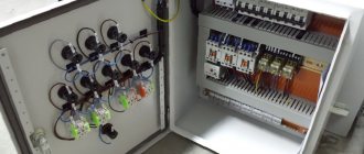
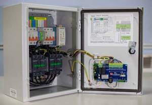
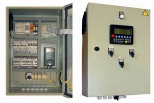
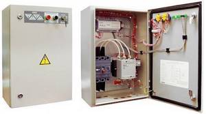
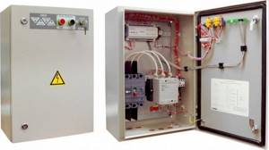
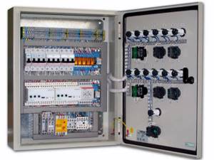
The fan control cabinet is equipped with a power supply, controllers, converters and a large number of on/off switches. The switches, in turn, are connected to electric heaters, heat recovery devices, fans, water heaters and refrigeration units. A mandatory element of the switchboard is a manual control unit, which assumes the functions of regulation and control in the event of a failure or malfunction of the automation. In addition, all cabinets are equipped with emergency alarm sensors that are triggered in the event of an emergency or pre-emergency situation.
A special role in monitoring the operation of ventilation systems is played by sensors, which are a kind of receptors and collect information about the performance of each node. With their help, you can get a clear picture of the pollution of air flows, their temperature and humidity, as well as the speed of movement of air masses and the speed of rotation of the fan blades. Temperature sensors are available in both digital and analogue versions, and when the temperature inside the system changes, they help switch the entire installation to another mode. Humidity sensors work on the same principle. The information received by the sensors is sent to automatic regulators, which, in turn, adjust the operation of key components of ventilation systems.
Based on their location, sensors are divided into external and internal. The first ones are often called atmospheric and are installed on the outside of buildings. Internal ones, in turn, are divided into channel and surface models. Ducts are installed inside air ducts on the walls or across the movement of air masses. Surface ones are placed on the surface of the nodes and remove parameters from these devices.
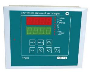
An equally important element of control cabinets are controllers. The devices receive information coming from sensors and process it automatically. After processing the parameters, the controllers send a signal to the main units of ventilation units, such as fans, heaters, refrigeration units, after which they change their operating mode. Functionally, the controller can either serve several devices or interact with only one of them. Universal models are often equipped with microprocessors, which makes them less bulky and can be easily placed in a small cabinet or stand.
Another element of the shield configuration is fan blade speed converters. Thanks to these devices, it is possible to regulate the number of engine revolutions, thereby significantly reducing the amount of electricity consumed by the installation. In addition to saving money, this leads to a significant reduction in wear on fan parts and extends the overall service life of the ventilation unit.
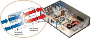
Organization of air circulation in the apartment
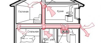
Let's consider how air circulates in a single apartment without installing additional air exchange devices.
As mentioned above, fresh air enters through all sorts of window cracks and gaps, as well as through doorways - ajar doors and cracks under them.
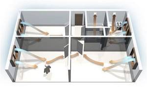
The diagram clearly shows the direction of air movement. It enters through windows or doors of living spaces and moves towards ventilation openings
Comfortable living in apartments is characterized by a number of factors, including the frequency of air exchange and the volume of regularly changing air.
There are standards regulating the flow of air flows.

Air exchange rate table suitable for an apartment building. Air change should occur more actively where there is high humidity, that is, in the kitchen and bathrooms
In older buildings, ventilation shafts do not always function 100%, and this can be checked in a simple way. You need to take a sheet of paper and attach it to the technical ventilation hole. If the piece of paper is not held by the force of traction and falls, natural ventilation is disrupted.
Instead of a sheet, you can use a burning candle or match. By the movement of the flame, it becomes clear whether there is a draft from the room to the outside.
We discussed in more detail the rules for checking ventilation in an apartment and ways to find the problem in another article.
Ventilation problems negatively affect the well-being of people living in apartments. The lack of fresh air causes unhealthy drowsiness, fatigue, and headaches.
People with diseases of the heart and respiratory system react especially sensitively to this. They constantly want to keep the vents and windows open, and this leads to a sharp cooling of the premises and, as a result, an increase in the number of colds.
We also recommend that you read the information on how to restore ventilation and air duct functionality.
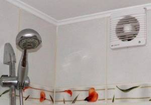
You can increase the efficiency of a natural exhaust system using a simple device - a fan installed in the ventilation outlet in the bathroom
If a regularly switched-on hood with air exhaust into the ventilation shaft is installed above the kitchen stove, this will also contribute to a rapid change of air masses in the kitchen and in adjacent rooms.
If desired, residents can independently organize the air flow. For this purpose, both ordinary ventilation and special mechanical and technical devices are used, for example, a supply valve for a window.
Image gallery
Photo from
Open windows are a traditional way to freshen up the atmosphere in your home.
Ajar windows and plastic double-glazed windows
Household supply valves on plastic windows
Split systems with fresh air transportation up to 15%
Valves are installed not only on double-glazed windows, but also in walls, most often under windows, near heating devices. Air from the street enters the room through a small hole with a diameter of 5 to 10 cm and is heated by the heat of a radiator or convector.
There are automatic models that are sensitive to changes in temperature and humidity: as soon as the parameters exceed the norm, ventilation occurs.
But a centralized channel-type supply system is recognized as more advanced. You can install it yourself only in a private house, because in high-rise buildings special services deal with systems of this scale.
Air ducts and air supply/heating devices are located above the rooms, in the ceilings, and pass through the walls, so they are installed during the construction process.

Supply duct ventilation is installed in new buildings of the so-called elite class. One of the installation conditions is high ceilings, allowing installation without damaging the interior
As you can see, the lack of a well-established natural ventilation system can be partially compensated for by installing additional devices. There is only one minus - additional one-time expenses for the purchase of devices and regular expenses for paying for electricity.
General information
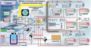
Ventilation control system is designed to monitor and control supply and supply and exhaust ventilation systems of buildings with a different set of equipment, which may include: recuperator, cooler, heater, control valves and pumps in the cooler and heater circuit, air dampers, filters.
Problems solved during the implementation of automatic control systems:
- automatic maintenance of the set temperature and air exchange rate in the serviced room;
- ensuring fire safety - controlling fire-retarding valves;
- timely diagnosis of ventilation equipment failures.
- maintaining the air temperature in the serviced premises within the limits specified by the controller program;
- continuous automatic protection of the water heat exchanger from freezing based on water temperature and supply air temperature, monitoring air filter contamination in the supply system;
- operation of ventilation systems in the “Day”/“Night” and “Winter”/“Summer” modes;
- monitoring the condition of controlled equipment.
The ventilation ACS exchanges information with the dispatch console, providing the following capabilities:
- transmission of technological parameters, messages about emergency situations and data on the operation of actuators to the control panel;
- remote control for individual mechanisms if necessary, while maintaining automatic control for the system as a whole, and incorrect operator actions are blocked;
- receiving commands from the dispatch console for unscheduled switching on and off, as well as temperature assignments in the serviced premises.
In addition to the main control mode from the dispatch console, it is possible to control ventilation systems locally from push-button control stations (CPC) located in the serviced premises.
The ACS hardware and software platform provides high configuration and programming flexibility. As a result, the following characteristics of the self-propelled gun are provided, distinguishing it from similar products:
- the ability to connect small ventilation systems to controllers of large ventilation systems without installing additional control cabinets;
- the ability to connect actuators of other engineering systems (fireproof valves, smoke removal fans, water pumping stations, etc.) to the controllers of ventilation units;
- the ability to implement modifications to the controller and control programs in a short time and at low cost in the event of changes in the original project for automation of engineering systems;
- flexibility of control algorithms, which allows them to be easily modified during the design of engineering systems if appropriate customer requirements arise;
- the ability to transfer information to the upper level using any standard protocols required by the dispatch system supplier.
Device diagram
Connection of control cabinets is carried out according to the standard scheme and is regulated by GOST R51321-1. Cabinets, stands and panels are installed in corridors, control rooms or utility rooms. If technical conditions exist, ventilation and fire control units are located in one cabinet, which is located in the control room. This will provide quick access to emergency and operational ventilation control panels and allow you to quickly respond to problems in the system.
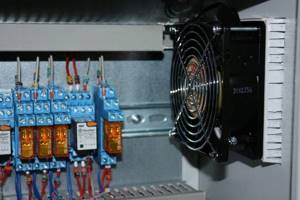
The rooms in which the panels are installed are subject to special requirements in terms of humidity and temperature. Devices must be reliably protected from direct ultraviolet rays, drops of water and dust. Magnetic vibrations and radio interference can also negatively affect the correct operation of devices, so their impact on devices should be limited. The temperature range at which operation of control cabinets is allowed is from -10 to +55 degrees. Installation of the device requires mandatory grounding, and the frequency of the mains current should not exceed 50 Hz. Electrical networks with voltages of 220 and 380 V are used as a power source.
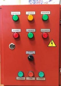
The main requirements of the layout are that all control devices are located on one stand and in the same plane. The most important components responsible for the safety of the device must be equipped with light indicators and preferably connected to a personal computer. In addition, devices responsible for the correct operation of the main components must be equipped with two types of control: manual and automatic. The most convenient for use are cabinets equipped with a remote control, allowing a person who does not have much experience in controlling ventilation to control its operation. In addition, the device connection diagram should be simple and extremely easy to understand. This will help you turn off the installation yourself in case of an emergency, without waiting for repair services to arrive.
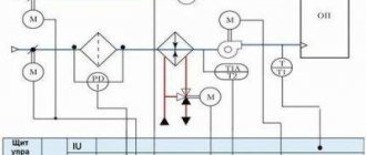
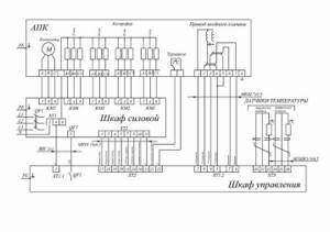
Electrical drive diagram of the ventilation unit
For installation, 4 fans driven by A.D. are used. with short circuit rotor D1-D4, which are protected by automatic switches A1-A4. The supply of voltage and protection of the power circuit is carried out by the automatic circuit breaker BA. For a small range of motor speed control, an AT autotransformer is used, the taps of which are switched on and off by contactors K1, K2, K3. To connect motors D3, D4, contactor K4 is used. The installation can operate in manual and automatic modes, which are set by the UP switch. Position +45 manual, -45 automatic. For manual control, switches PC1 and PC2 are used. in automatic mode, temperature relays PT1 and PT2 come into effect.
Let's consider the manual mode.
All circuit breakers are turned on. UE is set to position +45. PC1 and PC2 to position 1, if the temperature in the room exceeds the norm, the operator sets PC1 to position 2, the contactors K1 and KL are turned on and a reduced voltage is supplied to the motors D1 and D2. If the temperature continues to rise, the operator sets PC1 to position 3, K1 is turned off, K2 turns on. the voltage increases, but is below the nominal voltage. The rotation speed increases, with a further increase in temperature the PC is set to 4, K2 turns off, K3 turns on, the AT autotransformer is removed from the motor power supply circuit, i.e. The motors are supplied with rated voltage. If the temperature continues to rise, PC2 is set to position 2, K4 is turned on, and motor D3 and D4 are connected. The installation is running at full capacity.
In automatic mode, the switching sequence is the same, only the switching on and off of all contactors is carried out by the actuators of the temperature relays PT1 and PT2.
Typical interlocking connections in control circuits.
To perform a work cycle in automatic machine control circuits, there must be a relationship between different operating modes of the same mechanism or between individual machine mechanisms.
Schematic diagram of the relationship between setup and operating modes.
A) when the KnP button is pressed, voltage is applied to the coil of the contactor CL, its contact CL is closed, voltage is supplied to the motor stator D, and the engine starts working. The KnP button is bypassed by the CL contact, it can be released. The engine is stopped by pressing the KnS button, the CL coil loses power, and the CL contacts open. The adjustment mode is carried out by a two-contact button Kn Push, when pressed the CL is turned on, and when it is released the CL is turned off.
Schemes for turning off the engine when the movement of the mechanism is limited.
A) when the KnP is pressed, the CL is turned on, voltage is supplied to the motor stator D and the electromagnetic brake EMT, which releases the brakes on the motor rotor shaft. The engine starts running. When the mechanism reaches the extreme position, its stop opens the contact of the limit switch VK, the CL turns off, and the engine stops.
B) control diagram for the hydraulic feed drive of the machine.
When approaching the extreme position, the mechanism closes the limit switch VK, the time relay RV is turned on and the countdown of the delay time for closing the contacts RV begins, after which the contact RV closes, the intermediate relay RK is turned on, which with its contact turns on the electromagnet of the movement of the mechanism back EMN. The mechanism is retracted to its original position, controlled by the VKI limit switch, which opens and turns off the EMT.
Scheme for coordinating the operation of the main drive and the feed drive of the machine.
When voltage is applied to the circuit, the intermediate relay RP is turned on and its contact closes. When you press the KnP1 button, the KG contactor and D1 motor will turn on. When you press KnP2, the contactor Kp and the feed drive will turn on, at the same time the time relay PB will turn on, and its contacts PB will close. When you press KnS1 for a short time, the power supply to the RP will be lost, the CP and the feed motor will turn off, and the CG will receive power through the RP. Those. the main drive will not shut down. When you press KnS1 for a long time, after the time delay has expired, the PB contact will open and the KG will turn off.
Paper machine electrical equipment.
Requirements for paper machine drives.
1. maintaining a constant set speed level of the paper machine, which is necessary to maintain a mass of 1 square meter. produced fabric.
2. The speed level of the paper machine depends on the grades of paper produced. Therefore, to produce different grades of paper on one paper machine, a wide range of speeds is required.
3. for precise adjustment of the mass of 1 square meter. paper, the drive must provide smooth control of the speed level of the machine.
4. the ability to regulate and adjust the speed of each section of the machine relative to its operating speed. This is required to create tension on the paper web in the intersectional spaces to prevent the web from breaking.
Additional requirements include obtaining an auxiliary speed section to inspect the machine's clothing and warm up the dryer cylinders before running the machine at operating speed. For high-speed paper machines there are a number of other requirements.
1. for drying sections it is necessary to provide artificial braking when stopping.
2. the possibility of short-term increasing the speed of the calender to pull up the bags.
3. When the paper breaks in front of the calender, the cutoff on press 1 and the scrap conveyor should be automatically turned on.
4. When the screen part stops, the vacuum pumps should automatically turn off and the mass pumps of the headbox should stop.
To monitor the operation of the paper machine from the front side of the machine, instruments are installed at the main station that show the load of the entire machine. Indicators of paper speed and weight. Sound and light signals to notify about the fact and location of a paper break. Opposite each section, ammeters of sectional and auxiliary motors and indicators of relative speeds of sections are installed. Recently, control and regulation systems have been used on paper machines directly according to technological parameters using computers. Previously, due to high requirements for smooth control and accuracy of speed maintenance, a DC electric drive was used. Currently, it is being replaced with a frequency electric drive with A.D.
Types of electric drives.
In an electric transmission drive, individual sections of the machine are driven into rotation from a common transmission. The machine is driven into rotation from a common transmission. The older type of this drive is the drive with V-belt transmissions, the more modern is the drive with differential transmissions, the more modern is the drive with differential gears, which provides the required range and smoothness of regulation, but the manufacture of these regulators is technically complex. The multi-motor drive is modern, i.e. each section is driven by a separate motor. The drive motors of the sections can be powered from a common converter or from individual ones, which is the best option.
Diagram of the paper machine's multi-motor drive section.
The diagram shows a simplified block diagram of a B-15 paper machine section drive with power supply to each sectional motor from a controlled terristor converter.
Starting, stopping and changing the speed of sectional motors is achieved by regulating the voltage of sectional converters. Sectional DC converters receive power from a 6 kV network through step-down transformers TR. The excitation in the DC motor is independent OV-D, the voltage to the armature of the motor D is supplied through the contacts L of the contactor and the floating choke Dr. control of the signal arriving at the DC input is the output voltage of the two-circuit speed ratio control. It consists of a speed controller circuit PC and a current controller circuit PT. These regulators are made on the basis of UBSR elements. The use of these regulators having a proportionally integral transfer characteristic ensures high accuracy and speed of the section speed control system. Negative o.s. the speed is carried out by the TG tachogenerator, and the current feedback is from the shunt R and the DT current sensor. The speed of the section is determined by the voltages supplied to the input of the speed control system through the input summing filter VF.
1. leading voltage Uved, which determines the speed of the entire paper machine.
2. voltage that determines the auxiliary speed during adjustment and repair work Uv.s.
3. voltage of the section speed ratio setter Us.s.
smooth acceleration of the section is achieved by limiting the section motor current, for which purpose the PC has a current limiting unit BO. In the excitation circuits of drive motors united by common clothing and connected to one converter. There are excitation regulators that allow you to regulate the load distribution.
ELECTRICAL EQUIPMENT OF DEFIBRERS. DIAGRAM OF AUTOMATIC BALANCE SUPPLY REGULATOR.
They are used for high-quality production of wood pulp from prepared pulp. The balance is located parallel to the axis of the cylindrical rotating stone. And it is pressed against its surface using hydraulic presses and mechanical devices. the protrusions of the stone cut into the balance and tear off small fibers from it, which are washed off with water. A.D. are used for the main drive of stones. and s.d. power up to 5000 kW. Starting engines either directly or using reactors and autotransformers according to standard schemes. The quality of wood pulp largely depends on the constant pressure of the pulp on the stone. The magnitude of this pressure determines the power consumed by the drive motor of the stone. Therefore, at constant pressure and no change in the speed of rotation of the stone, the power consumption is also a constant value. By ensuring the constancy of power consumption, the constancy of the balance pressure on the stone will indirectly be ensured. There are various automatic devices that regulate the speed of feeding balances. The automatic balance feed regulators are based on the principle of controlling the power consumed by the main motor of the defibrator. Regulators are hydraulic and electric. Hydraulic regulators are a combination of electrical, hydraulic and mechanical elements.
Let's consider the circuit of the hydraulic feed drive. The hydraulic feed drive is used for screw and chain defibrators. Oil engine 1 drives screws or chains using pump 2, which forces oil under pressure from tank 3. Depending on the oil pressure in the engine, the supply of balance to the defibrator stones changes. Therefore, the supply of balances can be adjusted by increasing or decreasing the oil pressure. For this purpose, power regulator 4 is used, consisting of a number of concentrically located coils in the center, of which there is an aluminum drum. The coils are shifted relative to each other by 90 degrees. Some of the coils receive power from voltage transformer 5, some from current transformer 6. Because The current and voltage vectors are shifted by 90 degrees, then a rotating magnetic field is formed. This creates a rotating magnetic field. This field creates a torque of the aluminum drum, which is transmitted through the gear sector 7 to the flap 8, which closes the oil supply valve 9. At the same time, the pressure of the balance on the stone changes, and consequently the load of the defibrator motor. As the defibrator load increases, the current increases and the power regulator partially closes the valve9. when the load decreases, the drum tends to return to its original position under the action of a spiral spring and opens the valve. This is how the supply of balances and the power of the main engine are regulated. Resistors 10 are used to adjust the power regulator. The current transformer has a number of sections; using a special switch, you can connect a power regulator to one or another section and thereby manually regulate the power consumed by the main engine.
Calculation of ventilation systems
Calculating room ventilation at the first stage requires the correct selection of equipment that will have the necessary performance characteristics regarding the amount of air passed through (cubic meter/hour).
It is also considered very important to consider such a parameter as the air exchange rate. It characterizes the number of complete air changes within one hour inside a building
In order to correctly determine this parameter, it is necessary to take into account the norms and regulations of construction. The multiplicity depends on the purpose of using the room, what is in it, how many people, etc.
Calculating the ventilation of industrial premises according to this indicator also involves taking into account the equipment, as well as the characteristics of its operation and the amount of heat or moisture that it emits. For premises intended for human habitation, the air exchange rate is 1, and for industrial premises up to 3.
The brevity metrics generate a performance value that can be as follows:
- from 100 to 800 m³/h (apartment);
- from 1000 to 2000 m³/h (house);
- from 1000-10000 m³/h (office).
Also, air distributors must be designed and installed correctly. These include special air distributors, air ducts, turns, adapters, and so on.
Ensuring reliable and proper ventilation is an extremely important and necessary system in any building.
What is the ShchUV used for and where is it used?
Small household ventilation systems used in multi-storey buildings and the private sector do not require any additional devices. They are controlled remotely, using a remote control, or manually.
Unlike household ones, industrial systems have a much larger network length. Many functional devices, primarily fans, are initially installed in hard-to-reach places. Due to limited access, control is carried out using a unit equipped with a whole set of special equipment.
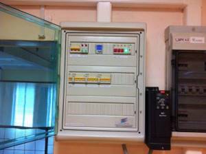
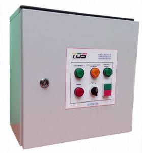
A modern ventilation control panel - SHCHUV is made in the form of a panel on which adjustment indicator devices are located, as well as in the form of metal cabinets fixed to the wall or installed on the floor. The internal space with the equipment located here is protected by hinged doors. To limit access to unauthorized persons, they are locked.
The main tasks that the ventilation control panel solves are as follows:
- Control over equipment, instruments and equipment included in ventilation systems.
- Protection of controlled devices in the event of emergencies caused by overheating, improper installation and connection, and short circuits.
- Regulatory functions – setting the required parameters for the performance and power of the equipment.
- The ability to program individual components and assemblies or the entire system for a certain period, from 1 day to 1 month.
- The control and adjustment processes of the ventilation control panel are greatly facilitated due to the installed indication.
- Each room can maintain its own temperature, which can be changed at the right time.
- Air filters, the degree of their contamination, as well as the condition of the internal walls of the air ducts are monitored.
- Control over the operation of seasonal equipment, which is subject to negative impacts due to sudden changes in outdoor temperature.
A ventilation system control panel installed on site allows you to constantly monitor work processes and the condition of all equipment while in one place. If some devices break down or stop, promptly detect them and fix them.
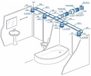
How is sewer ventilation done?
Removing unpleasant sewer odors is also necessary for comfortable living in apartment buildings. The sewerage “ventilation” system is simplified to the minimum: gases are removed through the same riser as the wastewater is discharged.
To prevent unpleasant odors from bothering residents, the riser is equipped with an extension that goes onto the roof - a ventilation (fan) pipe.
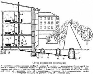
The diagram clearly shows how sewer ventilation is arranged. All apartment plumbing fixtures are “tied” to a common riser, which on one side ends with a drain pipe, on the other – with an outlet leading to the centralized city network
Knowing the diagram, you can understand why work on remodeling bathrooms requires permission. If you change the location of the riser or connect a large number of plumbing fixtures, the operation of the ventilation system may be disrupted.
When equipping the sewer network, taking into account the ventilation of the system, they are guided by SNiP 2.04.01-85 .
Functions of automatic ventilation cabinet
Thanks to the improvement of equipment in the field of ventilation automation, it has become possible to eliminate the human factor from the operation of the ventilation control cabinet. Automation guarantees a high level of safety due to the enormous functionality provided by ventilation controlled by cabinet actuators.
Wide range of ventilation control cabinet options include:
- Connection of any ventilation elements with different physical characteristics and different ports for system installation.
- Ability to control network voltage.
- Control of special electric valves to ensure continuous power in the electrical network. Increases the operation of devices, eliminating their overheating, short circuits, and overloads.
- Control of set parameters for the room and fan speed.
Standard Features
A typical ventilation automation cabinet has the following functions:
- Control of the heating temperature of an individual element of the ventilation system.
- Control over the operating parameters of the air valve drive.
- Monitoring the cleanliness of air filters. When dirty, an audible signal is sent to the ventilation equipment control unit.
- Controlling a valve to move air flows to maintain a given room temperature.
- The ventilation equipment unit is controlled manually, turning it on and off.
- Elimination of overheating and short circuit of the pump motor.
- Using indicator lights, you can obtain information about the operation of the system as a whole.
- Possibility of extending the stop time of movement of both supply and exhaust air using SHUV fans (ventilation control cabinet).
- Maintaining a log of failures in the operation of the forced ventilation system.
- Control of icing of parts of freon coolers.
Advanced Features
The set of advanced functions depends on the specific model of the SHUV device. Often used functions such as:
- Control of special valves to regulate pressure when the fan belt breaks.
- Automatic control of the amount of carbon dioxide.
- Saving all work data in logs after a power outage.
- Control over a special air flow mixing chamber.
- Programming a week in advance of the entire work process.
- Monitoring the parameters of the cooling valve.
- Control using an electric heater.
- Using the remote control.
- Implementation of effective work with sensors designed to monitor various room parameters using the cascade method.
What is automation for ventilation systems
Today, automatic ventilation control systems are represented by a large complex of various technical devices. All of them, from thermostats to complex computerized modules, are designed to facilitate the management and control of the operation of forced ventilation systems. The variety of equipment makes it possible to solve automation problems at any facility, regardless of its characteristics and purpose.
Based on operational and technical requirements, different approaches to the manufacture of automated ventilation control panels are possible:
- At some facilities, you can get by with standard modules produced in the form of cabinets with control devices installed in them.
- In other cases, installers have to manually assemble complexes adapted for complex supply and exhaust ventilation systems, taking into account specific tasks.
The difference in approaches is due to the need to ensure effective ventilation and create comfortable conditions for residents or workers in the interior of the building, regardless of the time of year and external weather conditions.
The operation of ventilation mechanisms is controlled using a set of sensors installed indoors. Some of them operate on the principle of a thermostat - as the temperature inside the building rises, fans automatically turn on, thereby ensuring a flow of fresh air.
Modern automated systems are equipped with elements of artificial intelligence and more complex instrumentation.
Structurally, similar modules consist of three groups of nodes:
- Sensors are devices that transmit information about the environment - thermostats, air humidity meters, gas analyzers. They transmit the collected data to the analyzing center.
- The control center collects and processes information coming from control sensors and, based on the analysis obtained, issues commands to control mechanisms to change the operating mode.
- Actuators are units that perform mechanical actions. This group includes: fan speed converter, servo drives for adjusting the position of valves, etc.
Control centers analyze the ratio of oxygen and carbon dioxide in the air, the percentage of humidity, and, if necessary, issue a command to ventilate the room. When a fire is detected, highly intelligent electronics independently block the flow of fresh air, preventing the spread of fire.
In normal mode, automation ensures the smooth functioning of all components and mechanisms of ventilation systems without the involvement of an operator.
Computerized modules transmit information about the operating mode and sensor readings to a single control panel. This allows the operator, if necessary, to adjust the operation of the automation and change settings remotely.
Depending on the specific situation, one of 3 device control modes is used:
- Manual. Ventilation control is carried out by an operator located directly in the control room or at a remote control panel.
- Autonomous. The equipment operates in accordance with the established settings, regardless of other engineering systems installed in the building.
- Auto. Control devices are integrated into the overall control of all engineering complexes of the building. The ventilation operation is synchronized with other devices and sensors located in the house - for example, with a fire alarm and other emergency sensors.
Thus, the automated complex plays the role of a control center. It starts the ventilation, stops it, processes sensor readings and sets the desired mode depending on temperature, humidity and other parameters.
Examples of ventilation schemes for a private house
The organization of effective ventilation must take into account the functioning of the heating system. The choice of the optimal forced or natural ventilation scheme in a private house depends on many factors: wall material, load-bearing structures and ceilings, number of floors, layout, etc. In addition, there are features of arranging ventilation elements for different rooms: living rooms, basement, kitchen, bathroom, etc.
General diagram for a one- or two-story house
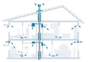
Ventilation in a private two-story house, wiring diagram in vertical section
- Indoor exhaust vent, with grille and filter membrane.
- Vents in the window frame.
- Vents in the wall of the structure. Equipped with dampers and filters.
- Holes for air circulation in interior partitions.
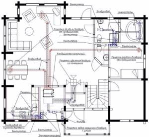
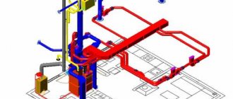
Layout diagram of the main elements of a ducted air conditioner of a forced ventilation system
For forced ventilation systems of the supply type in small buildings with an open plan, the location of the exhaust unit in the subceiling space of the central part of the room is typical. Fresh air is supplied to each room through separate air ducts.
Ventilation of kitchen, bathroom, toilet
It is recommended to equip the kitchen and bathroom with their own, autonomous forced air removal systems connected to the ventilation ducts of the building.
Forced ventilation in the house, diagram and arrangement of air ducts in the bathroom and toilet
In addition to the hood connected to the ventilation shaft, it is recommended to install several additional air ducts in the kitchen, embedded in a separate air duct.
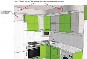
An example of the location of natural hood and forced ventilation in the kitchen
Ventilation of a cold, unused attic
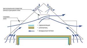
Scheme of air flow in the attic
Ventilation of an unused attic space is necessary to remove moisture, prevent dampening of thermal insulation materials in winter and cooling in summer. Air circulation is ensured naturally through a vent system. Slot vents are located in the lower part of the slope, through which air enters the attic. Air removal in the upper part of the slope is ensured by a gable grille or special ridge aerators.
Ventilation diagram for technical rooms
Technical rooms, such as a boiler room, garage or basement, are places with a high content of harmful substances in the air. In the garage, the main source of gas pollution is the car; in the boiler room, carbon monoxide. In addition, special attention should be paid to the flow of fresh air into the boiler room, since oxygen is necessary for the functioning of some types of boilers.
Basements and ground floors are located below ground level. Under unfavorable conditions, radon can accumulate in them, a radioactive carcinogenic gas that causes intoxication and, in high concentrations, death.
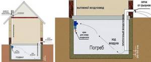
Exhaust hood diagram in a private house - location of exhaust and supply pipes in the basement
Traditionally, a passive supply and exhaust system is used for ventilation of technical, basement and semi-basement premises. It consists of two pipes with a diameter of 100-120 mm, located in different corners of the room and at different heights.
- Supply pipe. The inner end is at a distance of 20-50 cm from the floor surface, the outer end is 20-30 cm above the ground surface.
- Exhaust pipe. The inner end is at a distance of 20-30 cm from the ceiling, the outer end is brought out onto the roof, to a height of at least 100 cm above the ridge level. The exhaust pipe is additionally equipped with a deflector (at the top) and a faucet for draining condensate at the bottom, and is also insulated.
The external openings of the pipes must be closed with frequent grilles to prevent the penetration of rodents and insects. The use of a deflector is not mandatory, but is encouraged. With a deflector, especially in windy conditions, the efficiency of the system increases by an order of magnitude.
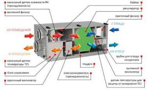
Types of supply and exhaust systems
The most effective ventilation systems are supply and exhaust systems that include recuperators in the design. These devices are heat exchangers that use the energy of exhaust air. In this case, the inlet flow and outlet do not come into direct contact. The recuperator can be rotary, plate or containing an intermediate coolant. The rotary one is highly efficient, but is considered the most expensive. Its use is uneconomical when the outside air temperature during the cold period does not fall below 15 degrees below zero. At the same time, air handling units with rotary heat exchangers, used in northern latitudes, provide double savings in energy costs for heating premises. The plate version of the device is more affordable and belongs to the budget segment.
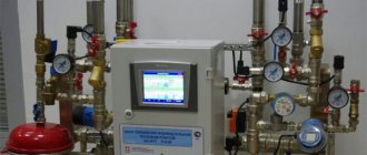
Installation with recuperator
During the cold season, the incoming air flow heats up the room and, when leaving, gives off heat to the newly incoming flow. The absence of mixing guarantees a constant flow of fresh, clean air and removal of waste air. In summer, when it's hot, the device works in reverse. The warm flow, entering the room, is cooled, and when leaving, it takes away heat from the newly entering one.
General circulation ventilation is a cheaper type. The air coming from outside receives heat by directly contacting the exhaust air.
In this case, the cleanliness of the air in the room can no longer be the same as in the above-described option. Circulation systems cannot be installed in buildings where the atmosphere may contain carbon and flammable gases, toxic substances and other components hazardous to life and health.
Another disadvantage of forced circulation ventilation is its ineffectiveness when the outside temperature drops below zero.
The most expensive options for air handling units with forced ventilation are systems equipped with air conditioners. The devices allow you to regulate the temperature in the room within a wide range and provide comfortable conditions all year round. The system is equipped with a heat pump and a filtration circuit necessary for air purification.
Each of the forced ventilation is provided with a control system. The most expensive options are equipped with sensors and “smart” electronics capable of adjusting modes independently, according to a predetermined program.
For ventilation of buildings, especially multi-storey buildings, not only mechanical air circulation can be used. The pressure difference inside and outside the room can create the flow necessary for ventilation. The device of supply and exhaust ventilation with natural circulation is based precisely on this principle. The following nuances are taken into account:
- To place the air intake, the side of the building that is most often blown by winds is usually selected.
- The withdrawal is made from the opposite side
- The air intake itself is equipped with a deflector that enhances the incoming flow.
This system is characterized by its simple design and low cost. However, simplicity excludes the possibility of saving heat and many of the advantages provided by installations with a forced type of ventilation: ionization, cleaning, humidity control.
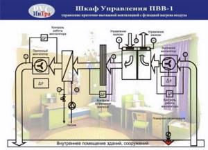
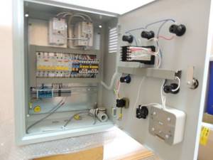
Functions of automatic ventilation cabinet
ventilation control cabinet "Rubezh-4A"
Capabilities of ventilation control cabinets:
- maintain the required constant power of the electrical network;
- allow you to conveniently connect lines of different power voltages to different terminal blocks;
- control the intensity of fan rotation, start them smoothly and prevent phase imbalance;
- equalize power, preventing equipment overheating, overload and short circuits;
- control the voltage in the network autonomously, remotely or locally.
The supply and exhaust ventilation control cabinet operates in standby or summer modes. In summer mode the air temperature is not controlled. When the supply air temperature is low, the cabinet automation switches the supply ventilation control to protection mode.
Standard Features
- Manual stop and start;
- compatible with temperature sensors of supply air, outside air, and return coolant;
- records the temperature of fan motor contacts;
- regulates the function of the air valve drive;
- prevents short circuits and overloads of the pump motor;
- controls the heat supply valve drive;
- prevents freezing of water heaters and freon coolers;
- prevents overheating of the electric heater;
- prolongs the shutdown of the supply air fan;
- gives signals about the need to clean the air filters;
- stops and de-energizes equipment during a fire alarm;
- notifies with the help of light indication about the operation of the system;
- records accidents in a special log.
Advanced Features
- Prevents pressure drops when the fan belt breaks;
- Provides frequency conversion for fans;
- Regulates indoor air temperatures in a cascade manner;
- compatible with the temperature sensor on the hood;
- notifies about an accident with a light indication;
- connection of remote control is possible;
- controls the operation of the air valve;
- provides connection of additional fans;
- two-phase control of the compressor-condenser unit;
- five-phase control by electric heater;
- controls the mixing chamber;
- prevents freezing of the recuperator and rotary regenerator;
- controls air humidifiers;
- programmable for 7 days;
- controls the cooler valve;
- controls recirculation dampers;
- if the heating power is insufficient, reduces the rotation speed of the fan blades;
- retains data in memory after power failure;
- controls carbon dioxide levels.
Upon request, manufacturers equip the cabinet for automatic ventilation control with additional features:
- work without sensors;
- recording reports on system operation;
- cold recovery;
- dispatcher remote or local control.
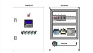
Construction of a ventilation panel for a system with the installation of an electric heater
Supply ventilation control panel with electric heater
To set up this switchboard, the following automation components are used:
- temperature control regulator (one of the best options would be to use Swedish parts from Regin);
- control group for fans of the supply and exhaust system. The best option is to install devices that provide stepwise or smooth adjustment;
- ventilation unit usage indicators;
- a group of devices to maintain the nominal temperature in the room;
- turning off the electricity supply to the heater when the supply fans are turned off;
- a group of devices for shutting down and indicating air filter contamination;
- protective shutdown device when the system overheats;
- automatic shutdown system for peak short circuit currents and significant overloads.
Elements of ventilation systems
The control system includes basic elements such as sensors, regulators and other actuators.
Sensors
Using sensors, you can obtain information about the state of the required object based on various parameters (temperature, pressure, humidity, etc.) and control it in the event of the slightest system failure. Sensors must be selected strictly in accordance with the conditions of a particular ventilation (operating conditions, range and degree of accuracy of measurements, etc.).
Temperature sensors are made for outdoor and indoor use; they can show the temperature on the surface of the pipeline or inside the channel (air duct). They are attached either to the pipes themselves (on their surface) - external ones, or perpendicular to the moving air flow in the pipe, air duct - duct sensors. Atmospheric sensors are installed outside the building, above its middle, on the leeward side, and indoor types of sensors must be mounted indoors, at a distance from the floor of at least 1 - 1.5 m.
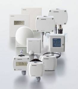
Ventilation and heating system sensors
Ventilation control also depends on sensors that regulate the degree of humidity; they can be used for room or duct purposes. Outwardly, they look like a block with a built-in electrical device that measures the relative humidity of the air and converts the received data into electronic signals. In order for the device to work more accurately, it must be installed at a certain distance from windows, heating devices, ventilation streams and sunlight.
Flow sensors are devices that measure the speed of flow (this can be either liquid or gas) in pipes and air ducts. The gas or liquid flow rate is calculated taking into account the cross-sectional area of the pipe.
Regulators
Regulators are necessary to control ventilation actuators. They receive signals from sensors, process their readings and activate the actuators of the ventilation system.
Control regulators for actuating ventilation mechanisms
Actuators
A device that begins its operation upon a command received from the regulator is called an actuator. They are divided according to the method of operation: electrical, mechanical, hydraulic, etc.
All processes that make up the entire ventilation control system are controlled through a device such as an electrical control panel.
Air distribution calculation
Before starting calculations, you need to understand the parameters of the air stream. First of all, it is assumed that there may be workplaces under a direct stream, because the boundaries of the zone can only be known after calculating the air distribution.
Moreover, in summer the temperature on the jet axis will be lower than the ambient air temperature, and in winter it will be higher. Thus, knowing the air exchange patterns, you need to determine which initial data to pay special attention to. Subsequently, based on them, choose one of the options for arranging air distributors.