Calculation of air duct network resistance program. The procedure for calculating pressure losses in air ducts
To determine the cross-sectional dimensions on any section of the air distribution system, it is necessary to perform an aerodynamic calculation of the air ducts. The indicators obtained from this calculation determine the performance of both the entire designed ventilation system and its individual sections.
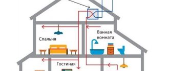
To create comfortable conditions in a kitchen, a separate room or a room as a whole, it is necessary to ensure the correct design of the air distribution system, which consists of many parts. An important place among them is occupied by the air duct, the determination of the quadrature of which affects the value of the air flow speed and the noise of the ventilation system as a whole. An aerodynamic calculation of air ducts will allow you to determine these and a number of other indicators.
Execution Sequence
It includes several stages, each of them determines a number of indicators, as well as their total values. All elements are formed in the form of tables.
- An axonometric diagram of the air distribution system is being developed and is being prepared for the calculation and selection of air duct sections.
- Aerodynamic resistance is calculated.
- The main line (main line) and branches are linked.
Stage one
This includes an aerodynamic calculation of mechanical air conditioning or ventilation systems, which includes a number of sequential operations. A diagram is drawn up in axonometry, which includes ventilation: both supply and exhaust, and is prepared for calculation.
The dimensions of the cross-sectional area of the air ducts are determined depending on their type: round or rectangular.
Formation of the scheme
The diagram is drawn up in axonometry with a scale of 1:100. It indicates points with located ventilation devices and the consumption of air passing through them.
Here you need to decide on the main line - the main line from which all operations are carried out. It is a chain of sequentially connected segments with the greatest load and maximum length.
When building a highway, you should pay attention to what kind of system is being designed: supply or exhaust.
Supply
Here the calculation line is lined up from the most distant air distributor with the highest consumption. It passes through supply elements such as air ducts and the ventilation unit right up to the place where the air is taken in. If the system must serve several floors, then the air distributor is located on the last one.
Exhaust
A line is drawn from the most distant
aspektnn.ru
Calculation of natural exhaust ventilation
Then, in connection with the opening of the upper and lower, respectively, supply and exhaust transoms in the room approximately in the center of the height of the structure, a degree of equal pressure is obtained, in this place the influence is also zero. Accordingly, the influence in the degree of concentration of the lower lumens will be equal to:
- where av is equal to the average temperature of the density of air masses in the room, kg/m3;
- h1 – height from the plane of equal pressure to the lower gaps, m.
At the level of the centers of the upper lumens, above the plane of equal pressures, an excess stress is formed, Pa, equal to:
It is this pressure that affects the air exhaust. The total voltage available for the exchange of air flows in the room:
Air duct resistance calculation calculator. Calculation of pressure in air ducts
When the parameters of the air ducts are known (their length, cross-section, coefficient of air friction on the surface), it is possible to calculate the pressure loss in the system at the designed air flow.
Total pressure loss (in kg/sq.m.) is calculated using the formula:
where R is the pressure loss due to friction per 1 linear meter of the air duct, l is the length of the air duct in meters, z is the pressure loss due to local resistance (with a variable cross-section).
1. Friction losses:
In a round air duct, pressure loss due to friction P tr is calculated as follows:
Ptr = (x*l/d) * (v*v*y)/2g,
where x is the friction resistance coefficient, l is the length of the air duct in meters, d is the diameter of the air duct in meters, v is the air flow speed in m/s, y is the air density in kg/cub.m., g is the acceleration of free fall (9 .8 m/s2).
Note: If the duct has a rectangular rather than a round cross-section, the equivalent diameter must be substituted into the formula, which for an air duct with sides A and B is equal to: deq = 2AB/(A + B)
2. Losses due to local resistance:
Pressure losses due to local resistance are calculated using the formula:
z = Q* (v*v*y)/2g,
where Q is the sum of the local resistance coefficients in the section of the air duct for which the calculation is being made, v is the air flow speed in m/s, y is the air density in kg/cub.m., g is the acceleration of free fall (9.8 m/s2 ). Q values are presented in tabular form.
Permissible speed method
When calculating the air duct network using the permissible speed method, the optimal air speed is taken as the initial data (see table). Then the required cross-section of the air duct and the pressure loss in it are calculated.
Procedure for aerodynamic calculation of air ducts using the permissible speed method:
Draw a diagram of the air distribution system. For each section of the air duct, indicate the length and amount of air passing in 1 hour.
We start the calculation from the areas farthest from the fan and the most loaded.
Knowing the optimal air speed for a given room and the volume of air passing through the air duct in 1 hour, we will determine the appropriate diameter (or cross-section) of the air duct.
We calculate the pressure loss due to friction P tr.
Using the tabular data, we determine the sum of local resistances Q and calculate the pressure loss due to local resistances z.
The available pressure for the following branches of the air distribution network is determined as the sum of pressure losses in the areas located before this branch.
During the calculation process, it is necessary to sequentially link all branches of the network, equating the resistance of each branch to the resistance of the most loaded branch. This is done using diaphragms. They are installed on lightly loaded areas of air ducts, increasing resistance.
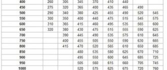
Table of maximum air speed depending on duct requirements
Constant head loss method
This method assumes a constant loss of pressure per 1 linear meter of air duct. Based on this, the dimensions of the air duct network are determined. The method of constant pressure loss is quite simple and is used at the stage of feasibility study of ventilation systems:
Depending on the purpose of the room, according to the table of permissible air speeds, select the speed on the main section of the air duct.
Based on the speed determined in paragraph 1 and based on the design air flow, the initial pressure loss is found (per 1 m of duct length). The diagram below does this.
The most loaded branch is determined, and its length is taken as the equivalent length of the air distribution system. Most often this is the distance to the farthest diffuser.
Multiply the equivalent length of the system by the pressure loss from step 2. The pressure loss at the diffusers is added to the resulting value.
Now, using the diagram below, determine the diameter of the initial air duct coming from the fan, and then the diameters of the remaining sections of the network according to the corresponding air flow rates. In this case, the initial pressure loss is assumed to be constant.
Diagram for determining pressure loss and diameter of air ducts
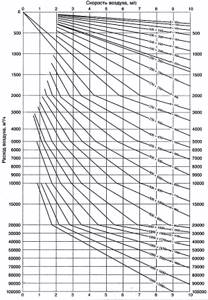
The pressure loss diagram shows the diameters of round ducts. If rectangular air ducts are used instead, then it is necessary to find their equivalent diameters.
mizhu.ru
Calculation of exhaust ventilation example
Before starting the calculation of exhaust ventilation, it is necessary to study the SN and P (System of Norms and Rules) design of ventilation systems. According to SN and P, the amount of air required for one person depends on his activity.
Low activity – 20 cubic meters/hour. Average – 40 kb.m./hour. High – 60 kb.m./h. Next, we take into account the number of people and the volume of the room.
In addition, you need to know the frequency - a complete exchange of air within an hour. For a bedroom it is equal to one, for living rooms - 2, for kitchens, bathrooms and utility rooms - 3.
For example, calculate the exhaust ventilation of a room of 20 sq.m.
Let's say two people live in a house, then:
In the same order, we calculate the exhaust ventilation performance of the entire house.
Calculation of pressure losses in fan pressure air ducts
The heart of any ventilation system with mechanical airflow is the fan, which creates this flow in the air ducts. The power of the fan directly depends on the pressure that must be created at the outlet, and in order to determine the value of this pressure, it is necessary to calculate the resistance of the entire channel system.
To calculate pressure losses, you need a diagram and dimensions of the air duct and additional equipment.
Initial data for calculations
When the diagram of the ventilation system is known, the dimensions of all air ducts have been selected and additional equipment has been determined, the diagram is depicted in a frontal isometric projection, that is, axonometry. If it is carried out in accordance with current standards, then all the information necessary for the calculation will be visible on the drawings (or sketches).
Aerodynamic characteristics of the fan.
- Using floor plans, you can determine the lengths of horizontal sections of air ducts. If the heights at which the channels pass are marked on the axonometric diagram, then the length of the horizontal sections will also become known. Otherwise, sections of the building with laid air duct routes will be required. And in extreme cases, when there is not enough information, these lengths will have to be determined using measurements at the installation site.
- The diagram should show, using symbols, all additional equipment installed in the channels. These can be diaphragms, electrically driven dampers, fire dampers, as well as devices for air distribution or exhaust (grills, panels, umbrellas, diffusers). Each piece of this equipment creates resistance to the air flow, which must be taken into account when calculating.
- In accordance with the standards, air flow rates and channel sizes must be indicated on the diagram next to the conventional images of air ducts. These are the defining parameters for the calculations.
- All shaped and branching elements must also be reflected in the diagram.
If such a diagram does not exist on paper or in electronic form, then you will have to draw it, at least in a draft version; you cannot do without it when doing calculations.
Return to contents
Where to start?
Diagram of pressure loss for each meter of duct.
Very often you have to deal with fairly simple ventilation schemes, in which there is an air duct of the same diameter and there is no additional equipment. Such circuits are calculated quite simply, but what if the circuit is complex with many branches? According to the method for calculating pressure losses in air ducts, which is set out in many reference publications, it is necessary to determine the longest branch of the system or the branch with the greatest resistance. It is rarely possible to determine resistance by eye, so it is customary to carry out calculations based on the longest branch. After this, using the air flow rates indicated on the diagram, the entire branch is divided into sections according to this criterion. As a rule, costs change after branches (tees) and when dividing it is best to focus on them. There are other options, for example, supply or exhaust grilles built directly into the main air duct. If this is not shown in the diagram, but such a grid is available, you will need to calculate the flow rate after it. Areas are numbered starting from the one furthest from the fan.
Return to contents
Calculation order
Table of maximum air speed.
The general formula for calculating pressure losses in air ducts for the entire ventilation system is as follows:
HB = ∑(Rl + Z), where:
- HB - pressure loss in the entire air duct system, kgf/m²;
- R—friction resistance of 1 m of air duct of equivalent cross-section, kgf/m²;
- l is the length of the section, m;
- Z is the amount of pressure lost by the air flow in local resistances (shaped elements and additional equipment).
Note: the value of the cross-sectional area of the air duct involved in the calculation is initially taken as for a circular duct shape. The frictional resistance for rectangular channels is determined by the cross-sectional area equivalent to a round one.
The calculation starts from the most distant section No. 1, then moves to the second section and so on. The calculation results for each section are added up, as indicated by the mathematical summation sign in the calculation formula. The parameter R depends on the diameter of the channel (d) and the dynamic pressure in it (Рд), and the latter, in turn, depends on the speed of the air flow. The absolute wall roughness coefficient (λ) is traditionally accepted as for an air duct made of galvanized steel and is 0.1 mm:
R = (λ / d) Rd.
Diagram for determining pressure loss and diameter of air ducts.
It makes no sense to use this formula in the process of calculating pressure losses, since the values of R for various air velocities and diameters have already been calculated and are reference values (R.V. Shchekin, I.G. Staroverov - reference books). Therefore, it is simply necessary to find these values in accordance with the specific conditions for the movement of air masses and substitute them into the formula. Another indicator, dynamic pressure Рд, which is associated with the parameter R and is involved in the further calculation of local resistance, is also a reference value. Given this relationship between the two parameters, they are listed together in the reference tables.
The Z value of pressure loss in local resistances is calculated using the formula:
Z = ∑ξ Рд.
The summation sign means that you need to add up the calculation results for each of the local resistances in a given area. In addition to the already known parameters, the formula contains the coefficient ξ. Its value is dimensionless and depends on the type of local resistance. Parameter values for many elements of ventilation systems have been calculated or determined experimentally, and therefore are found in reference literature. The local resistance coefficients of ventilation equipment are often indicated by the manufacturers themselves, having determined their values experimentally in production or in the laboratory.
Table of equivalent duct diameters.
Having calculated the length of section No. 1, the number and type of local resistances, you should correctly determine all the parameters and substitute them into the calculation formulas. Having received the result, move on to the second section and further, all the way to the fan. At the same time, we should not forget about the section of the air duct that is located behind the ventilation unit, because the fan pressure should be enough to overcome its resistance.
Having completed the calculations for the longest branch, the same ones are performed for the adjacent branch, then for the next one, and so on until the very end. Typically, all these branches have many common areas, so the calculations will go faster. The purpose of determining pressure losses on all branches is their overall coordination, because the fan must distribute its flow evenly throughout the entire system. That is, ideally, the pressure loss in one branch should differ from the other by no more than 10%. In simple terms, this means that the branch closest to the fan should have the highest resistance, and the one farthest should have the lowest resistance. If this is not the case, it is recommended to return to recalculating the diameters of the air ducts and the speed of air movement in them.
When for some reason it is impossible to link the branches, additional artificial resistances are installed in them - diaphragms, which should be selected. To simplify the process, instead of diaphragms, throttle valves are installed; with their help, the resistance of the branch can be adjusted by blocking the flow with a damper.
As practice shows, a correctly calculated and adjusted ventilation system after installation works flawlessly.
1poclimaty.ru
Subtleties of choosing an air duct
Knowing the results of aerodynamic calculations, you can correctly select the parameters of the air ducts, or more precisely, the diameter of the round sections and the dimensions of the rectangular sections. In addition, in parallel, you can select a forced air supply device (fan) and determine the pressure loss during the movement of air through the channel.
Knowing the amount of air flow and the speed of its movement, you can determine what cross-section of air ducts will be required.
To do this, take the formula inverse to the formula for calculating air flow:
S = L/3600*V.
Using the result, you can calculate the diameter:
D = 1000*√(4*S/π),
Where:
- D is the diameter of the air duct section;
- S – cross-sectional area of air channels (air ducts), (m²);
- π is the number “pi”, a mathematical constant equal to 3.14;.
The resulting number is compared with factory standards approved by GOST, and the products closest in diameter are selected.
If you need to choose rectangular rather than round air ducts, you should determine the length/width of the products instead of the diameter.
When choosing, they are guided by the approximate cross-section, using the principle a*b ≈ S and size tables provided by manufacturers. We remind you that according to the standards, the ratio of width (b) and length (a) should not exceed 1 to 3.
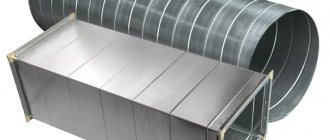
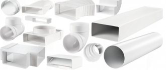
Air ducts with a rectangular or square cross-section have an ergonomic shape, which allows them to be installed flush against walls. This is used when installing home hoods and masking pipes above suspended ceiling structures or above kitchen cabinets (mezzanines)
Generally accepted standards for rectangular channels: minimum dimensions - 100 mm x 150 mm, maximum - 2000 mm x 2000 mm. Round air ducts are good because they have less resistance and, accordingly, have minimal noise levels.
Recently, convenient, safe and lightweight plastic boxes have been produced specifically for indoor use.
CLIMATE WORLD No. 49 (2008) : Magazine archive : Home
With this material, the editors of the magazine “CLIMATE WORLD” continue the publication of chapters from the book “Ventilation and air conditioning systems. Design recommendations for industrial and public buildings.” Author Krasnov Yu.S.
The aerodynamic calculation of air ducts begins with drawing an axonometric diagram (M 1: 100), putting down the numbers of sections, their loads L (m3/h) and lengths I (m). The direction of the aerodynamic calculation is determined - from the most distant and loaded area to the fan. When in doubt when determining a direction, consider all possible options.
The calculation begins from a remote section: the diameter D (m) of a round or the cross-sectional area F (m2) of a rectangular air duct is determined:
The recommended speed is as follows:
| at the beginning of the system | near the fan | |
| Administrative buildings | 4…5 m/s | 8…12 m/s |
| Industrial buildings | 5…6 m/s | 10/…16 m/s |
The speed increases as you approach the fan.
According to Appendix H from [30], the nearest standard values are taken: DCT or (a x b)st (m).
|
| Rice. 1. Axonometric diagram of the air duct |
Actual speed (m/s):
| or |
Hydraulic radius of rectangular ducts (m):
| Reynolds criterion: Re=64100×Dst× υfact (for rectangular air ducts Dst=DL). Hydraulic friction coefficient: λ=0.3164⁄Re-0.25 at Re≤60000, λ=0.1266⁄Re-0.167 at Re>60000. Pressure loss at the design section (Pa): |
where is the sum of the local resistance coefficients in the air duct section.
Local resistances at the border of two sections (tees, crosses) are assigned to the section with lower flow.
Local resistance coefficients are given in the appendices.
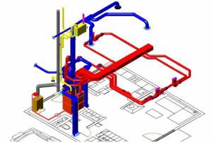
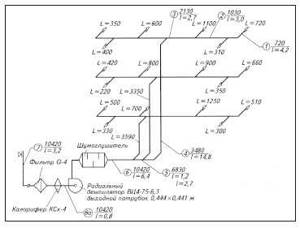
Diagram of the supply ventilation system serving a 3-story administrative building
Calculation example Initial data:
| No. of plots | flow L, m3/h | length L, m | υrec, m/s | section a × b, m | υf, m/s | Dl,m | Re | λ | Kmc | losses in the area Δр, pa |
| PP grid at the outlet | 0,2 × 0,4 | 3,1 | — | — | — | 1,8 | 10,4 | |||
| 1 | 720 | 4,2 | 4 | 0,2 × 0,25 | 4,0 | 0,222 | 56900 | 0,0205 | 0,48 | 8,4 |
| 2 | 1030 | 3,0 | 5 | 0,25× 0,25 | 4,6 | 0,25 | 73700 | 0,0195 | 0,4 | 8,1 |
| 3 | 2130 | 2,7 | 6 | 0,4 × 0,25 | 5,92 | 0,308 | 116900 | 0,0180 | 0,48 | 13,4 |
| 4 | 3480 | 14,8 | 7 | 0,4 × 0,4 | 6,04 | 0,40 | 154900 | 0,0172 | 1,44 | 45,5 |
| 5 | 6830 | 1,2 | 8 | 0,5 × 0,5 | 7,6 | 0,50 | 234000 | 0,0159 | 0,2 | 8,3 |
| 6 | 10420 | 6,4 | 10 | 0,6 × 0,5 | 9,65 | 0,545 | 337000 | 0,0151 | 0,64 | 45,7 |
| 6a | 10420 | 0,8 | Yu. | Ø0.64 | 8,99 | 0,64 | 369000 | 0,0149 | 0 | 0,9 |
| 7 | 10420 | 3,2 | 5 | 0,53 × 1,06 | 5,15 | 0,707 | 234000 | 0.0312×n | 2,5 | 44,2 |
| Total losses: 185 | ||||||||||
| Table 1. Aerodynamic calculation | ||||||||||
| Note. For brick channels with an absolute roughness of 4 mm and υf = 6.15 m/s, correction factor n = 1.94 ([32], Table 22.12.) |
The air ducts are made of galvanized sheet steel, the thickness and size of which correspond to approx. N from [30]. The material of the air intake shaft is brick. Adjustable grilles of the PP type with possible sections: 100 x 200; 200 x 200; 400 x 200 and 600 x 200 mm, shading coefficient 0.8 and maximum air outlet speed up to 3 m/s.
The resistance of the insulated intake valve with fully open blades is 10 Pa. The hydraulic resistance of the heating unit is 100 Pa (according to a separate calculation). Filter resistance G-4 250 Pa. The hydraulic resistance of the muffler is 36 Pa (according to acoustic calculations). Based on architectural requirements, rectangular air ducts are designed.
The cross-sections of brick channels are taken according to table. 22.7 [32].
Local resistance coefficients
Section 1. PP grid at the outlet with a cross section of 200×400 mm (calculated separately):
Dynamic pressure:
| Lattice KMC (Appendix 25.1) = 1.8. Pressure drop in the grid: Δр - рД × KMC = 5.8 × 1.8 = 10.4 Pa. Design fan pressure p: Δrvent = 1.1 (Δraerod + Δrvalve + Δrfilter + Δrcal + Δrglush) = 1.1 (185 + 10 + 250 + 100 + 36) = 639 Pa. Fan flow: Lvent = 1.1 x Lsyst = 1.1 x 10420 = 11460 m3/h. The selected radial fan VTs4-75 No. 6.3, version 1: L = 11500 m3/h; Δrven = 640 Pa (fan unit E6.3.090-2a), rotor diameter 0.9 x Dpom., rotation speed 1435 min-1, electric motor 4A10054; N = 3 kW installed on the same axis as the fan. Unit weight 176 kg. Checking fan motor power (kW): |
According to the aerodynamic characteristics of the fan, nvent = 0.75.
| No. of plots | Type of local resistance | Sketch | Angle α, deg. | Attitude | Rationale | KMS | ||
| F0/F1 | L0/Lst | fprokh/fstv | ||||||
| 1 | Diffuser | 20 | 0,62 | — | — | Table 25.1 | 0,09 | |
| Retraction | 90 | — | — | — | Table 25.11 | 0,19 | ||
| Tee-pass | — | — | 0,3 | 0,8 | Adj. 25.8 | 0,2 | ||
| ∑ = | 0,48 | |||||||
| 2 | Tee-pass | — | — | 0,48 | 0,63 | Adj. 25.8 | 0,4 | |
| 3 | Branch tee | — | 0,63 | 0,61 | — | Adj. 25.9 | 0,48 | |
| 4 | 2 bends | 250 × 400 | 90 | — | — | — | Adj. 25.11 | |
| Retraction | 400 × 250 | 90 | — | — | — | Adj. 25.11 | 0,22 | |
| Tee-pass | — | — | 0,49 | 0,64 | Table 25.8 | 0,4 | ||
| ∑ = | 1,44 | |||||||
| 5 | Tee-pass | — | — | 0,34 | 0,83 | Adj. 25.8 | 0,2 | |
| 6 | Diffuser after fan | h=0.6 | 1,53 | — | — | Adj. 25.13 | 0,14 | |
| Retraction | 600 × 500 | 90 | — | — | — | Adj. 25.11 | 0,5 | |
| ∑= | 0,64 | |||||||
| 6a | Confusion in front of the fan | Dg=0.42 m | Table 25.12 | 0 | ||||
| 7 | Knee | 90 | — | — | — | Table 25.1 | 1,2 | |
| Louvre grille | Table 25.1 | 1,3 | ||||||
| ∑ = | 1,44 | |||||||
| Table 2. Determination of local resistances | ||||||||
Krasnov Yu.S., “Ventilation and air conditioning systems. Design recommendations for industrial and public buildings", chapter 15. "Thermocul"
What we wrote about 15 years ago
Cold summer of 2003
Before the start of the last season, all market participants unanimously predicted its growth. The only difference of opinion was how much the market would increase. And indeed, all objective indicators indicated that sales would go up. In the first quarter of 2003, GDP growth amounted to a record 7–8%, prices for air conditioners fell once again, despite the fact that household incomes in dollar terms have already been growing by 15% per year for many seasons.
How to Counteract the Dangers of Air Duct Fires
Recently, the number of fires and even explosions inside the air ducts of ventilation and air conditioning systems has sharply increased. Although such fires have always occurred, recent changes have caused much larger fires involving more people.
Analysis of promising heat supply systems
This report examines issues related to the transition of centralized heating systems to decentralized ones. The positive and negative aspects of both systems are considered. The results of a comparison of these systems are presented.
mir-climate.info
Calculation of supply and exhaust ventilation
AIR HEATER
In the middle climate, the air entering the room must be heated. To do this, supply ventilation is installed with heating of the incoming air.
Heating of the coolant is carried out in various ways - with an electric heater, the intake of air masses near radiator or stove heating. According to SN and P, the temperature of the incoming air must be at least 18 degrees. Celsius.
Accordingly, the power of the air heater is calculated depending on the lowest (in a given region) street temperature. Formula for calculating the maximum heating temperature of a room with an air heater:
Calculation of pressure loss in air ducts in a ventilation and air conditioning system
When the parameters of the air ducts are known (their length, cross-section, coefficient of air friction on the surface), it is possible to calculate the pressure loss in the system at the designed air flow.
Total pressure loss (in kg/sq.m.) is calculated using the formula:
P = R*l + z,
where R is the pressure loss due to friction per 1 linear meter of the air duct, l is the length of the air duct in meters, z is the pressure loss due to local resistance (with a variable cross-section).
1. Friction losses:
In a round air duct, pressure loss due to friction P tr is calculated as follows:
Ptr = (x*l/d) * (v*v*y)/2g,
where x is the friction resistance coefficient, l is the length of the air duct in meters, d is the diameter of the air duct in meters, v is the air flow speed in m/s, y is the air density in kg/cub.m., g is the acceleration of free fall (9 .8 m/s2).
- Note: If the duct has a rectangular rather than a round cross-section, the equivalent diameter must be substituted into the formula, which for an air duct with sides A and B is equal to: deq = 2AB/(A + B)
2. Losses due to local resistance:
Pressure losses due to local resistance are calculated using the formula:
z = Q* (v*v*y)/2g,
where Q is the sum of the local resistance coefficients in the section of the air duct for which the calculation is being made, v is the air flow speed in m/s, y is the air density in kg/cub.m., g is the acceleration of free fall (9.8 m/s2 ). Q values are presented in tabular form.
Permissible speed method
When calculating the air duct network using the permissible speed method, the optimal air speed is taken as the initial data (see table). Then the required cross-section of the air duct and the pressure loss in it are calculated.
Procedure for aerodynamic calculation of air ducts using the permissible speed method:
- Draw a diagram of the air distribution system. For each section of the air duct, indicate the length and amount of air passing in 1 hour.
- We start the calculation from the areas farthest from the fan and the most loaded.
- Knowing the optimal air speed for a given room and the volume of air passing through the air duct in 1 hour, we will determine the appropriate diameter (or cross-section) of the air duct.
- We calculate the pressure loss due to friction P tr.
- Using the tabular data, we determine the sum of local resistances Q and calculate the pressure loss due to local resistances z.
- The available pressure for the following branches of the air distribution network is determined as the sum of pressure losses in the areas located before this branch.
During the calculation process, it is necessary to sequentially link all branches of the network, equating the resistance of each branch to the resistance of the most loaded branch. This is done using diaphragms. They are installed on lightly loaded areas of air ducts, increasing resistance.
Table of maximum air speed depending on duct requirements
| Purpose | Basic Requirement | ||||
| Silence | Min. head loss | ||||
| Main channels | Main channels | Branches | |||
| Inflow | Hood | Inflow | Hood | ||
| Living spaces | 3 | 5 | 4 | 3 | 3 |
| Hotels | 5 | 7.5 | 6.5 | 6 | 5 |
| Institutions | 6 | 8 | 6.5 | 6 | 5 |
| Restaurants | 7 | 9 | 7 | 7 | 6 |
| The shops | 8 | 9 | 7 | 7 | 6 |
Note: air flow speed in the table is given in meters per second
Constant head loss method
This method assumes a constant loss of pressure per 1 linear meter of air duct. Based on this, the dimensions of the air duct network are determined. The method of constant pressure loss is quite simple and is used at the stage of feasibility study of ventilation systems:
- Depending on the purpose of the room, according to the table of permissible air speeds, select the speed on the main section of the air duct.
- Based on the speed determined in paragraph 1 and based on the design air flow, the initial pressure loss is found (per 1 m of duct length). The diagram below does this.
- The most loaded branch is determined, and its length is taken as the equivalent length of the air distribution system. Most often this is the distance to the farthest diffuser.
- Multiply the equivalent length of the system by the pressure loss from step 2. The pressure loss at the diffusers is added to the resulting value.
Now, using the diagram below, determine the diameter of the initial air duct coming from the fan, and then the diameters of the remaining sections of the network according to the corresponding air flow rates. In this case, the initial pressure loss is assumed to be constant.
Diagram for determining pressure loss and diameter of air ducts

www.air-ventilation.ru
Table No. 1. Recommended air speed for various rooms
| Purpose | Basic Requirement | ||||
| Silence | Min. head loss | ||||
| Main channels | Main channels | Branches | |||
| Inflow | Hood | Inflow | Hood | ||
| Living spaces | 3 | 5 | 4 | 3 | 3 |
| Hotels | 5 | 7.5 | 6.5 | 6 | 5 |
| Institutions | 6 | 8 | 6.5 | 6 | 5 |
| Restaurants | 7 | 9 | 7 | 7 | 6 |
| The shops | 8 | 9 | 7 | 7 | 6 |
Based on these values, the linear parameters of the air ducts should be calculated.
Stage three: linking branches

When all the necessary calculations have been carried out, it is necessary to link several branches. If the system serves one level, then branches not included in the main line are linked. The calculation is carried out in the same order as for the main line. The results are entered into the table. In multi-storey buildings, floor branches at intermediate levels are used for linking.
Linking criteria
https://www.youtube.com/watch?v=ytcreatorsen-GB
Here the values of the sum of losses are compared: pressure along the linked sections with a parallel connected main line. It is necessary that the deviation is no more than 10 percent. If it is determined that the discrepancy is greater, then the linkage can be carried out:
- by selecting the appropriate cross-sectional dimensions of the air ducts;
- by installing diaphragms or throttle valves on the branches.