Creating an optimal indoor microclimate and providing comfortable conditions for living and working is not only a requirement of sanitary standards, but also a guarantee of people’s health. At the same time, it is important to take into account the economic factor so that heating the building and providing hot water supply can be achieved with minimal financial costs. In order to save coolant, carry out flexible adjustment of indoor microclimate parameters and heat metering, individual heating points are installed (the abbreviation is more often used, the decoding is ITP).
What is ITP? This is a complex consisting of elements of thermal installations, ensuring the distribution of coolant between consumers with the ability to adjust its parameters (temperature, supply modes, etc.) and metering. This complex is located in a separate technical room, and the heating units are connected to the heating network (central transformer substation, combined heat and power plant or boiler house). With the help of IHP, heating, hot water supply (hereinafter referred to as DHW) and ventilation can be provided. In multi-apartment residential buildings, ITPs are most often located in basements; it is also possible to install equipment in extensions to buildings or in separate technical structures (practised in industrial enterprises).
Currently, new houses are increasingly being designed taking into account the need to install IHP; in old buildings, procedures are being carried out to modernize heating networks, allowing the installation of heating points (TS). This popularity is explained by the benefits that ITP provides to end consumers, including:
- Significant (up to -40%) reduction in coolant consumption and consumer costs for heating and hot water supply.
- Protection of internal networks from increased temperature or pressure of the coolant.
- Ensuring operational safety and low accident rate.
- Providing accounting for the amount of coolant consumed.
- Full automation of IHP control with the ability to remotely regulate coolant supply modes (external temperature conditions, seasonality, time of day, etc. can be taken into account).
- Possibility of installing ITP of various types in almost any building.
Principle of operation
The operating principle of IHP in any building depends on the source of coolant. Usually they are served by an autonomous boiler house or thermal power plant, a combined heat and power plant (CHP). The heat source is connected to the heating point through the main heating network, and the heating substation is connected to the end consumers through secondary distribution heating networks. Having given the heat to consumers, i.e. Having ensured the operation of the hot water supply system and heating system, the coolant returns through the return line to the heat supply enterprise. There it is recharged and heated to a given temperature, after which it is again supplied through the main heating networks to the heating point and then distributed among consumers.
If a heating and power plant acts as a heat source, then the temperature of the coolant supplied to the heating point from large suppliers is, as a rule, 150-70oC, 130-70oC, 115-70oC (two numbers - the temperature of the supply coolant and the return temperature). In order to lower the temperature of the supplied coolant to a level acceptable to consumers, there are 2 options:
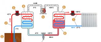
- With an independent connection, plate heat exchangers (HE) are used - the coolant (water) from the heating network circulates through them, heating the internal closed network.
- With dependent connection (this type is considered obsolete), elevator units are installed or pumps are used that mix the coolant from the return line to the supply line.
Coolant circulation is ensured by circulation pumps. Pressure regulators protect the complex from an emergency increase in pressure in the network. The specified temperature of the coolant supplied to consumers in modern transformer substations is ensured using automation: the heating station operator sets the required values or selects the ITP operating mode (for example, with a decrease in temperature at night).
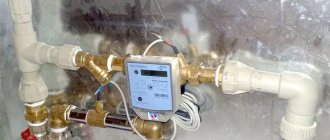
A mandatory element of any heating station is a heat metering unit. With its help, the amount of coolant consumed is recorded. Due to the presence of a meter, the consumer has the opportunity to pay only for the resource actually consumed by him: with the modernization of the heating network and the rational consumption of heat, the amounts in payments for heat are significantly reduced.
Purpose and principle of operation of the elevator in the heating system
Thermal stations or large boiler houses are capable of providing hot coolant to large areas. In this regard, the length of heating networks can reach tens of kilometers, which causes significant heat losses in the mains. Therefore, the initial temperature of the coolant from stations and boiler houses is selected taking into account these heat losses. Regulatory documents establish several modes of temperature parameters for the supply and return of heating networks, the main ones being 150 / 70, 130 / 70, 95 / 70.
Since, for safety reasons and to reduce losses, the temperature in the radiator heat exchangers of buildings should not exceed 95 °C, many consumers of thermal energy in buildings located at a short distance from heating plants have to solve the problem of partial cooling of water heated to temperatures of about 150 or 130 °C.
This can only be achieved by mixing the incoming and cooled return flow in a tee assembly. However, if mixing is carried out in a conventional tee, there will be no water flow in it and, accordingly, the movement of the coolant through the pipeline will stop. Therefore, a narrow nozzle is made in the mixing unit in the path of the feed flow. This leads to an increase in the speed of the water flow and, accordingly, a decrease in its pressure in the nozzle area, which is directly related to the diameter of the pipeline. As a result, the turbulent flow carries along water masses from the return, thus ensuring the movement of the coolant along the circuit.
A tee with an internal narrowed nozzle is the type of fitting that is called an elevator unit.
It should be noted that the elevator simultaneously performs the functions of a mixer and a circulation pump that pushes the coolant through the heating circuit. To the listed works you can add its functioning as a pressure reducer and a thermostat that reduces the temperature to the required parameters.
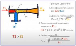
Rice. 2 Elevator calculation formulas
ITP for a single building
Designed to serve one residential building, administrative building, industrial premises. When designing ITP, ready-made block heating units can be used.
TsTP - central TP
They are designed to provide heating and hot water supply for microdistricts, several buildings, and large industrial enterprises. When creating central heating stations, block heating points can be used. Houses and buildings with ITP installed in them can be connected to the central heating point.
BTP - block heating point
BTP, or block heat substation, is a product completely ready for commissioning, which is used to create an ITP or central heating substation. The BTP is supplied assembled and is quickly connected to the heating network using flanges. To significantly reduce the costs of designing and installing an IHP or central heating point and simplify the design of the heating point itself, it is enough to buy a block heating point from a company specializing in the sale and maintenance of heat exchangers and BTP.
Electricity addiction
Now let's return to energy dependence. When does a heating system need electricity to function, and when can it be done without?
Solid fuel boilers
The canonical solution is a conventional steel or cast iron boiler with a water jacket in the firebox and mechanical adjustment of the blower using a thermostat. This unit is completely energy independent.
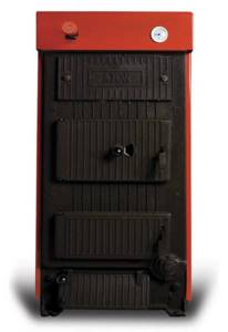
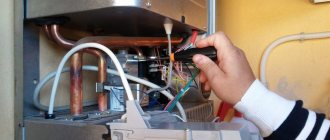
The photo shows a classic solid fuel boiler.
However, this design has an important drawback: the boiler requires frequent loading of fuel. Three technical solutions allow you to make heating as independent from humans as possible:
- A hopper and a conveyor belt supply new portions of sawdust or pellets as the fuel burns out. Electricity is required at a minimum for the transporter to operate.
- A solid fuel pyrolysis boiler divides combustion into two stages: pyrolysis of wood with a limited supply of oxygen and combustion of the resulting gas. In this case, the gas combustion chamber is located below the pyrolysis chamber. The movement of combustion products against the vector of natural draft requires the operation of an electric fan.
- An upper combustion boiler can operate on one load of coal for up to five days. Only the top layer of fuel smolders; air is supplied to it from top to bottom, and the ash is carried away by a stream of hot combustion products. Air circulation is provided by... that's right, an electric fan.
Gas
Non-volatile gas heating boilers use manual ignition using a piezoelectric element and flame regulation by a mechanical thermostat. When the main burner is extinguished at a high coolant temperature, the pilot burner continues to operate.
Floor-standing gas boiler with piezo ignition.
Boilers with electronic ignition stop the gas supply completely when idle. As soon as the coolant cools below the critical temperature, the discharge ignites the main burner and heating resumes. In addition, electricity often drives a blower fan that supplies air to the burner.
Which scheme is better? If you have frequent power outages, a non-volatile gas heating boiler would be more appropriate. Precisely because he is able to do without electricity in principle. On the other hand, these devices are less economical: up to 20% of the total gas consumed is spent maintaining the pilot flame.
Another useful feature that gas-independent heating boilers lack is the ability to control the weather and control it using an external thermostat, which takes the temperature, for example, in a remote room. Of course, we are also not talking about programming the temperature for a day or a week.
Solara
Everything is simple here: solar boilers are COMPLETELY identical to gas boilers with electronic ignition. Only the burners differ. In fact, a lot of dual-fuel units are being produced.
It is clear that without a forced-air fan and electronic ignition, the devices simply will not be able to work.
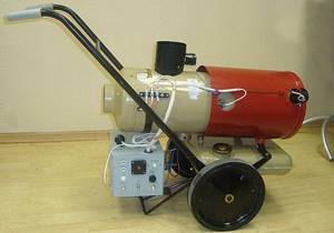
There are no rules without exceptions. The independent household heater OB1 0010 is equipped with its own generator and does without external power, generating electricity for the fan independently.
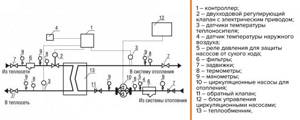
Schematic diagram of ITP
When designing ITP, the following equipment is used:
- Circulation pumps,
- sensors,
- controllers with t sensors,
- control valves on electric drives;
- control units,
- shut-off and control fittings, valves.
The simplest circuit diagram of an ITP designed using this equipment is as follows:
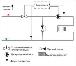
In dependent and independent schemes for connecting the heating system to external mains of the heat supply organization, different equipment is used.
The ITP diagram for dependent connection of the building’s heating system to the heating networks of a thermal power plant or boiler house is as follows:
Water circulation is ensured by the operation of pumps controlled automatically by a control unit or controller. The set temperature regime is maintained by controlling the control valve. In the scheme under consideration, the temperature regime of the circulating water can be adjusted using a jumper with a check valve. It allows you to mix cooled coolant from the return line with hot water. An alternative is the option with an elevator unit.
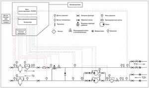
The ITP diagram with an independent connection type is shown below:
The main feature is the use of a heat exchanger and special filters for cleaning and preparing the coolant for entry into the maintenance facility and the intra-house heating network. Coolant circulation is also carried out using pumps controlled automatically using a control unit or controller.
On what principle does the point operate?
The most common ITP connection scheme is an independent heating and independent closed hot water system. The operating principle for an individual heat supply object consists of the following processes:
- The supply pipeline supplies the point with coolant, which, in turn, releases thermal energy to heaters and ventilation.
- Next, the carrier rushes to the return pipeline, and then, for reuse, to the main line of the enterprise, where primary heat generation occurs.
- What volume of coolant is consumed by consumption points to replenish heat losses.
- Water (cold) from the water supply flows through the pump through the pipes. Then part is heated and flows into the DHW circulation circuit, part is given to consumption points.
- Hot water, circulating through the system, gradually heats the containers (radiators, pipes), which release heat.
How the thermal unit works
The design of each heating unit depends on the customer's requirements. In practice, several schemes are used:
- Thermal unit based on an elevator. The simplest scheme, which is considered obsolete, the main disadvantage of which is the inability to flexibly regulate the temperature of the coolant, especially during transitional temperature conditions (if it is from +5 to minus 5C outside). Consequently, saving coolant also turns out to be inaccessible. In the elevator unit, the coolant from the main network is mixed with water from the return line, thereby achieving an acceptable temperature for supply to consumers. Mixing is carried out according to the principle of ejection due to the presence of a nozzle of a certain diameter in the design of the elevator unit.
- Thermal unit based on a plate heat exchanger. A modern and effective version of the design of a thermal unit, in which real savings in coolant and flexible adjustment of its temperature and pressure are possible. Such a TP allows you to separate the coolant entering through the heating main from the coolant that moves through the intra-house networks. Due to this separation, it becomes possible to prepare the coolant by adding special additives to it and filtering it, as a result, you can safely install aluminum radiators in houses. With this scheme, the coolant is mixed through the operation of thermostatic valves. In a similar way - i.e. through heat exchangers - DHW can also be connected.
Details - Advantages and Disadvantages
Each type of heating point for a private house or apartment has certain advantages and disadvantages. The advantages are:
- The point is capable of serving a huge number of users.
- Technical characteristics of the thermal fluid - pressure, temperature will be maintained and controlled automatically.
There are many more disadvantages to this solution:
- Each user will receive a strictly dosed thermal volume, but such shares are equal exclusively at the level of the central heating point. Due to the different lengths of the pipeline, residents of buildings will receive water at different temperatures.
- The longer the pipeline, the greater the heat loss. Because of this, it is necessary to increase the temperature at the central heating point, which will lead to increased costs for hot water and heating.
- During repair work, a huge number of residents will be left without heat.
- The circulation of hot water is uneven, and houses located far from the central heating point will need to drain cold water for a long time before receiving hot water. The meter will take into account the entire volume as hot water consumption.
But individual heating points are much more profitable:
- Heat losses are less when transferring coolant, and installing an individual system in a building will help save from 15 to 25% of costs.
- All apartments will receive the same amount of heat, taking into account the area of the apartment.
- Hot water will actually come out of the tap, and immediately.
- Since the heating unit operates without high loads, the likelihood of breakdowns is several times less, and repairs and installation of the necessary equipment will take less time.
- If a heating unit fails, fewer residents will suffer.
The disadvantages of individual complexes are associated only with its limited capabilities, and the heating point serves only one house or part of it. To modify the complex for further service of the microdistrict, quite a lot of financial investments will be required. The advantages and disadvantages of a modular heating unit are determined by its purpose, but this system also has its own advantages:
- Installation is quite simple - it just needs to be connected to the heating circuit and electrical networks.
- Ready-made modules take up a minimum amount of space, and even if we are talking about a central heating unit, it can be installed in the basement.
The higher the level of automation of a heating unit, the lower the costs for its maintenance and upkeep.
Working principle
The operating principle of a heating point in an apartment building is simple. The liquid from the main line begins to transfer heat through the heat exchanger to the heating and hot water supply system. After this, the coolant will be transferred through the return pipeline to the energy central or boiler room, where it is heated again. The heated liquid from the heating point is distributed among all consumers. The heating point will provide users with heating media and hot water. The operating diagrams of the systems differ. Tap water will begin to flow into the heating point, and part of the unheated water will be supplied to users, and the rest will be heated in the first stage heaters. The heated water enters the circulation circuit, and the pump will ensure constant movement of hot water along the circuits from the heating unit to consumers and back. Residents of the house draw hot water as needed.
Since the liquid gradually cools, it is regularly reheated in the second stage heater. Due to the fact that the volume of water in the circuit decreases, it is necessary to constantly draw cold water, heat it and replenish the missing volume. The operating diagram of a heating unit in an apartment building is slightly different, and it is simpler - water, giving off heat to pipes and heating radiators, returns in almost the same volume in which it was supplied. Leaks do occur, but the risk is low. The make-up system makes up for losses because it operates on the basis of primary heating networks.
Key components in a substation
The thermal complex includes the following main elements:
- A heat exchanger is an analogue of thermal boilers in a boiler room, and here the heat from the liquid in the main heating networks is transferred to the heat carrier of the heating point. We are talking about an element of a modern complex.
- Pumps – feed, circulation, booster and mixing.
- Dirt filter - it is installed at the outlet and inlet of the pipeline.
- Temperature and pressure regulators.
- Shut-off valves - will begin to operate in the event of a leak or an emergency change in parameters.
- Heat metering unit.
- Distribution comb – distributes thermal fluid to consumers.
- Heat metering unit.
Now let's talk about how to choose systems.
Selection of systems
The preparation of water for transfer to users is carried out through a control unit. Based on the type of such element, different operating schemes of the thermal unit are distinguished.
Elevator - it is installed on old models of heating points. In this case, the unit will mix liquid from the main network and cooled water from the return pipeline to produce a coolant with a temperature suitable for secondary networks. The temperature will be maintained at a certain level regardless of the air temperature indoors or outdoors. When overheating, the only method to remove excess heat is to open the window. If there is underheating, you will need to connect electric heaters.
The scheme of thermal units with controllers is much more effective, because the monitoring equipment and heat exchanger make it possible to regulate the water temperature level in the heating circuit according to real air parameters.
Let's highlight a couple of systems of this type:
- Dependent circuit - will reduce or increase the temperature of the supplied liquid by mixing the cooled coolant from the return pipeline. The controller monitors temperature changes and automatically connects valves and pumps. Installation of pressure regulators is required, since this indicator differs in primary and secondary networks.
- Independent - the water used for home heating will circulate in a closed circuit, and the heat from the coolant from the main will be transferred only through a heat exchanger. Pressure level regulators are not required here, everything happens faster and more accurately. The price of a heating point using an independent scheme is much higher, but the complex is economical to use - the water is not polluted, will not overheat, and will not lead to pipe and radiator corrosion.
The hot water supply system will also be implemented according to the following schemes:
- Single-stage - water from the water supply system will be supplied to the heater, and it is heated by means of a mesh coolant that comes from the source. The cooled network supply will be transmitted to the source, and the warmed water supply will be supplied to users.
- Two-stage - the water will be heated in 2 stages, and first due to the heat carrier from the return pipeline, which ranges from +5 to +30 degrees, and then it is heated through the use of a supply heat wire to +65 degrees. In this case, the waste energy of the return pipeline is used, since it is much cheaper.
The more efficiently a heating point reduces the price of heat supply services, the more expensive the installation will be.
System balancing
The calculations for each hydraulic system are quite complex. During installation, features and deviations begin to appear that are impossible to take into account during calculations - scale, blockages and narrowings. In reality, hydraulics are linked during design, and then they are adjusted using pressure balancing valves at the heating station of a multi-story building. We are talking about an adjustable washer, through which the valve capacity, or rather the hydraulic resistance, is changed. This way the work of all circuits will be connected. Balancing valves are installed on all heating point systems and components - pumps, heat exchanger, ventilation/water supply/heating circuits. additional devices are needed to coordinate contour work and compensate for pump operation.
Installation efficiency
An individual heating unit in a high-rise significantly reduces costs for heating and hot water supply:
- An individual heating point works according to a schedule - at night it reduces the temperature, the pumps stop working, and in the morning the load increases.
- Closed heat supply systems are the most profitable - there is no need to constantly purify water or repair radiators and pipes. Heat losses in closed systems are very small.
- Automation will reduce maintenance costs, and the most accurate temperature control will also reduce costs.
Heating points save 1.5-8 million rubles over 5 years.
Main types of heating points
Thermal units, through which the heating system, hot water supply system and ventilation are connected to a source of thermal energy, are of two types: single-circuit and double-circuit. Let's take a closer look at each of them.
Single-circuit TP
In this case, the heating system of a residential building, administrative or industrial building is directly connected to the DHW main. A distinctive feature of this type of heating points is the presence of an elevator unit - a pipeline connecting the forward and return lines. It was the single-circuit TP circuit that we considered above when we were talking about a thermal unit based on an elevator. Note that such a scheme may involve the installation of an additional circulation pump, or a special form of main pipes is used - first there is a sharp section of narrowing, and then a cone-shaped expansion, as a result of which water from the return line is pumped into the network (the principle of ejection works).
Double-circuit heating point
This scheme was discussed above when talking about a thermal unit based on TO. A plate heat exchanger is a device consisting of a number of hollow plates, along one of which the heated liquid (water) moves, and along the other – a heating liquid (water). By changing the number of plates interacting with each other, it is possible to regulate the amount of heat removed so that additional intake from the return is not required. Heat exchangers have high efficiency and are reliable and unpretentious equipment.
Diagram of an elevator heating unit
In any building, including a private house, there are several life support systems. One of them is the heating system. In private houses, different systems can be used, which are selected depending on the size of the building, the number of floors, climate conditions and other factors. In this material we will analyze in detail what a thermal heating unit is, how it works and where it is used. If you already have an elevator unit, then it will be useful for you to learn about the defects and how to eliminate them.
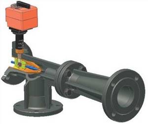
This is what a modern elevator unit looks like. The unit shown here is electrically driven. There are also other types of this product.
In simple words, a heating unit is a complex of elements that serve to connect the heating network and heat consumers. Surely readers have a question whether it is possible to install this unit yourself. Yes, you can if you know how to read diagrams. We will look at them, and one scheme will be analyzed in detail.
Installation steps
To put a heating point into operation, you need to go through several stages:
- Submitting an application to a specialized company for the design of a TP.
- Development of technical specifications.
- Obtaining technical specifications (TU).
- Direct design of the TP and approval of the project.
- Concluding an agreement with a heat supply company.
- TP test.
If we are talking about ITP in an apartment building, then the very first stage is obtaining the consent of the owners of the apartments of the building to install the equipment (the issue can be submitted to a general meeting). The following package of documents is submitted to the regulatory authorities:
- Specifications for connection;
- certificate from the heat supply organization;
- agreed project;
- passport of the installed ITP;
- certificate of the fact of concluding an agreement with the heat supply organization;
- act of permission to commission installations;
- other documents (the complete list may differ in each region).
Balancing the system
Balancing valves are adjusted after installation of the equipment and startup of the coolant.
Calculations of any hydraulic circuit are very complex. During installation, features and deviations appear that cannot be taken into account during calculations: blockages, scale, narrowing. In practice, hydraulics are linked at the design stage, and then adjusted using balancing valves. This device is an adjustable washer. With its help, the valve capacity, that is, the hydraulic resistance, is changed. In this way, the work of all circuits is connected.
Balancing valves are installed on all components and systems of TP: heat exchanger, pumps, water supply, ventilation, heating circuits. Additional devices are required to coordinate the operation of the circuits and compensate for the operation of the pumps.
ITP of an apartment building
The operation scheme of the ITP of a residential high-rise building does not differ from the standard scheme for a single building. Sometimes, instead of ITP, the abbreviation AITP is found - automated heating point; it is assumed that in it the parameters of the coolant, operating mode, etc. can be adjusted using electronics.
The ITP of an apartment building is connected to the main heating network. Heat to the ITP comes from the boiler house, central heating substation or from the combined heat and power plant. The ITP distributes it between the heating, hot water supply and ventilation systems (if it is connected to the ITP).
When installing ITP in a residential building, residents receive the main advantage - savings on housing and communal services. By adjusting the temperature and the amount of coolant consumed, taking into account the outside temperature and even the time of day (at night, during sleep, you can slightly reduce the temperature), you can reduce the cost of paying for the services of heat supply companies.
It should be noted that almost all ITPs that are now installed in apartment buildings are automated and operate on heat exchangers, which ensures maximum accuracy in adjusting the coolant temperature and almost 40% savings.
Types of circulation in heating circuits
To deliver heat to the batteries, you need to move the coolant heated by the boiler. Natural circulation is used in the heating system and forced movement of water using a circulation pump. Natural circulation is used in simple heating systems; it requires a minimum of equipment with minimal installation and operating costs.
To implement this method of moving the coolant, a change in the physical properties of water when heated is used. The speed of movement depends on the temperature difference and on the magnitude of hydraulic resistance, which is reduced by increasing the diameter of the pipes.
Open heating circuit
An open gravity heating system with natural circulation has undoubted advantages.
Advantages of open natural coolant circulation:
- simplicity and low installation costs;
- efficiency;
- easily converted into a system with forced circulation; the circulation pump is usually installed in the “return”.
Therefore, the heating system for a one-story house with natural circulation is very popular and is successfully used. The main disadvantages of such heating are high inertia. In addition, the presence of an open expansion tank determines the answer to the question - is it possible to pour antifreeze into the heating system of a house. You can fill it, but it will constantly evaporate, which will make the operation of the system unprofitable.
Closed heating circuit
The coolant in a closed heating system has no contact with atmospheric air. To compensate for thermal expansion, sealed membrane expansion tanks are installed. A closed heating system can have any design; it is equipped with a circulation pump to move the coolant. The absence of contact of the coolant with air significantly increases the service life of pipes and heating circuit equipment.
If during installation the slope of the pipes is provided, then in the absence of mains voltage and the bypass is switched, natural circulation will occur in the closed heating system of the house. Of course, the efficiency of the system will drop, but the heating will be operational and will continue to heat the home.
The main advantages of a closed heating system:
- the use of a sealed expansion tank eliminates the evaporation of liquid; in closed systems, antifreeze can be used as a coolant;
- the absence of contact between water and air protects circuit elements from internal corrosion;
- a closed heating circuit has low inertia and high efficiency;
- the use of a circulation pump allows you to reduce the diameter of the pipes and reduce the cost of purchasing them;
- for heated floors and complex branched circuits, an additional pump is installed in the heating system, which will ensure their efficient operation.
Which is better: ITP or TsTP?
Central heating stations are installed where it is necessary to provide heat to several buildings at once. ITP is designed to supply heat to one building or residential building. Hence the main differences between them. ITP is designed to solve a specific narrow problem, therefore, like any individual solution, it has more advantages. These include:
- Possibility of setting a specific heating temperature for each building. If we are talking about central heating stations, then most often those buildings that are located closer to the boiler room turn out to be overheated, and those further away, on the contrary, do not receive enough heat.
- Elimination of heat loss in the pipelines of the hot water supply system and the heating network (the heat exchanger is located in the same building). When connecting several buildings to the central heating point, such losses are inevitable.
- Reducing the risk of emergency shutdown. If a central heating station breaks down, residents or workers of all connected buildings find themselves without heat and hot water.
- Ease of maintenance and preventive repairs.
Thus, the central heating point and the ITP are designed to solve various problems, however, due to the smaller number of connected buildings and subscribers, the ITP is a more flexible system that provides maximum opportunities for savings.
Areas of application
IHP for heating air in the ventilation system
TP are necessary for proper distribution of heat between consumers. These include:
- Hot water supply. Part of the heat, as hot water is supplied through pipes, is used to heat the bathroom and kitchen.
- Heating systems – maintain a comfortable temperature in residential and public spaces.
- Ventilation system – the air is heated before entering the building.
- Cold water supply does not apply to consumers, but to supply elements. Cold water serves as a regulator.
They install TP for heating, water supply, air conditioning in both old and new buildings.
Operational safety
Modern AITPs provide maximum safety for both the personnel they serve and consumers. The main condition: the heating unit must be serviced by workers who have undergone special training and have the appropriate permits. They should be familiarized with the operating rules of a specific ITP and technical documentation.
The basic rule that should be followed for the safe operation of ITP: pumping equipment and automation are prohibited from starting in the absence of coolant and when the shut-off valves at the inlet are closed. In addition, persons servicing ITP must control:
- Pressure levels on pressure gauges installed on pipelines.
- Noise and vibration indicators (they must be within normal limits).
- Heating of electric motors of installations.
- Flushing the systems before starting the heating station.
It is important to remember that if there is pressure in the system, disassembling the regulators is prohibited and it is also prohibited to use excessive force when manually operating the valve.
Service
- Connecting a reading device and then taking readings.
- Analyzing errors and finding out the reasons for their occurrence.
- Checking the integrity of seals.
- Analysis of results.
- Checking technological indicators, as well as comparing thermometer readings on the supply and return pipelines.
- Adding oil to the liners, cleaning the filters, checking the grounding contacts.
- Removing dirt and dust.
- Recommendations for the correct operation of internal heating networks.