Home / Electric boilers
Back
Published: 05/28/2019
Reading time: 3 min
0
2435
Purchasing a high-quality boiler for a private home is only half the way to stable operation of the equipment. Proper installation is of great importance, which determines effective heating of the premises. Incorrect wiring of the electric boiler will lead to defective, energy-consuming and unsafe operation.
This is also fraught with rapid wear. To avoid installation errors, you must follow the advice of experts and be guided by the rules and regulations. It is important to understand what kind of piping is required for an electric heating boiler and how it should be equipped.
- 1 Why do you need to properly tie an electric boiler?
- 2 Connection features
- 3 Classic piping 3.1 Electric boiler piping diagram
Features of operation and connection of the electric boiler
If we talk about the operating features of this type of boiler unit, the main thing is the connection to the electrical supply network. There are strict requirements here:
- separately laid cable from the distribution board;
- installation of a serious security system on site: automatic machines, RCDs, etc.;
- accurate calculation of all connection elements taking into account power consumption;
- installation of an electric boiler taking into account the requirements and provisions of the PUE.
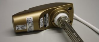
The operating principle of the unit is simple. The design contains a container, inside of which an electric heater is installed. This could be a heating element, electrodes or an induction coil. Two pipes are connected to the tank. One is where water flows in, while the other is where it flows out, already heated.
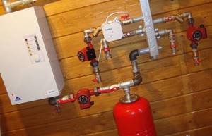
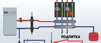
Electric boiler wiring
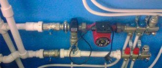
There are models on the market without circulation pumps and with them. The first make it possible to simplify the strapping. But if the second ones are installed, then you can additionally purchase a circulation pump and install it in the boiler piping.
Location of the boiler in the heating system
The main element in the heating circuit is the heating unit. The scheme according to which the piping of the heating boiler will be carried out largely depends on the type of this device.
The main rule for installing floor-standing models shown in the photo is that they cannot be placed at the highest point of pipe distribution. If this condition is not met, then air pockets will form in the boiler without a device for removing trapped air. In this case, the supply pipe that exits the unit should be placed strictly vertically.
The fact that an automatic air vent is built into the model of an electric or gas boiler is indicated by the presence of pipes in its lower part, to which the supply pipe and return pipe are connected. They are usually installed in electric or gas wall mounted equipment (pro
What is electric boiler piping
In the context of the topic, the word “piping” has one meaning - connecting an electric boiler to the heating system of a house using pipes. The installation of other elements that affect the efficiency of the boiler unit is also taken into account, such as:
- expansion tank;
- circulation pump;
- heating process monitoring and control system.
The piping of boilers of different types, that is, those operating on different types of fuel, is the same. Because a boiler is just a heating element. And it doesn’t matter what fuel it runs on. But there are nuances. For example, the piping of solid fuel and electric boilers differs from each other in that in the first, steel pipes are used in the process of connecting to pipelines.
The entire heating pipe system can be assembled from polypropylene, but the connection areas to the boiler must be steel. In this case, the length of each such segment should not be less than 1 m. This is done for one reason - the high heating temperature of the boiler unit. Polypropylene pipes in the boiler piping may become deformed. Everything else is the same.
Installation
Even the simplest piping, which is done by hand, requires a competent choice of pipes. Products as simple and beloved by many people as polypropylene pipes also need to be used correctly. The ease of operation should not be misleading, although you only need to use a soldering iron. It is allowed to use PN25 pipes, which are reinforced from the inside with aluminum foil.
To connect to a heated floor, you can tie the boiler with pipes of category PN10. Their walls are very thin and are designed to pump water heated to +45 degrees under a pressure of 1000 kPa. Polymer pipelines can be used in both open and hidden installation schemes, but thermal expansion must be taken into account. The connection of fittings to pipes is done either by creating a thread or using cold (hot) welding. Thread cutting simplifies the matter, but the cost of such a solution immediately increases.
Before welding begins, the foil must be cleaned, otherwise the strength of the connection can be forgotten. Glass fiber does not require such treatment when used for reinforcement. Cold welding using specialized glue is now almost out of use, since it does not guarantee a reliable joint. If two small heating boilers or more are installed in the system, piping with parallel oriented passages is allowed. As practice shows, this can be more economical than using a single boiler of the same amount of power.
To prevent water from moving through temporarily disconnected circuits, it is very important to ensure that they are closed with separating valves and other shut-off valves. In some cases, the equipment is mounted on a foundation pad (clay, 0.1 m high), on top of which sheet iron or asbestos is placed
The main requirement is to install the boiler at a lower level than installing the batteries. You need to resort to copper pipes only if you plan to heat a house with very high temperatures and pressures. In all other cases, there is no point in these expensive components.
Materials used
Previously, steel pipes were mainly installed. They quickly failed due to corrosion. Also, their internal diameter during operation decreased over time due to salt build-up. This reduced the efficiency of the heating system and electric boiler.
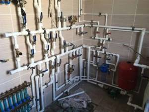
Polypropylene pipe piping
Tying with polypropylene pipes
Steel has been replaced by plastic in the form of polypropylene, which not only has a service life of 50 years, but is also several times cheaper. Piping with such pipes is easy. This means that prices for installation work are reduced.
Positive characteristics of polypropylene pipes:
- the inner diameter never changes;
- the inner surface is always smooth, which does not reduce the speed of water flow;
- speed of installation;
- withstand pressure up to 25 bar and temperature up to +95 ℃;
- high quality connections between pipes and other elements of the heating system.
There is only one drawback - linear deformation with increasing coolant temperature.
Pipe connections are made in two ways: using special fittings or soldering. The second option is more reliable in terms of not causing leaks at the joints.
Copper piping
An excellent option, but expensive in all respects:
- the price of copper pipes is higher even than steel pipes;
- the cost of the services of a welder and installer will be more expensive, because joining requires knowledge of the technology, the availability of a welding machine and consumables, and extensive experience in carrying out this type of work.
The advantages of using copper pipes in piping include:
- their long-term operation, not inferior to polypropylene. Copper does not react corrosively with hot water;
- high heat transfer. Copper products themselves will give off heat well into the room, thereby acting as additional heating elements for the house.
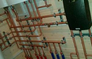
Piping an electric boiler with copper pipes
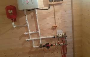
Sequence of work
It all starts with the installation of an electric boiler. It can be mounted either on the wall (wall-mounted model) or on the floor (floor-standing). Further according to the following scheme:
- The pipes of the heating system are connected to the pipes.
- The latter include the required additional network elements: expansion tank, circulation pump, temperature, pressure sensors and others.
It makes no difference what needs to be done first: the heating network or the installation of the boiler. The main thing is to choose the right location for installing the boiler unit. It should be convenient for servicing the equipment.
Piping diagram of a natural circulation system
There is no pump here. Such boilers are often used in heating networks with natural coolant movement. When hot water heats up, according to the laws of physics, it tends to rise. It passes along the upper section of the piping and goes down to the heating radiators, because it is supported by cold water moving along the opposite section.
Here the coolant transfers heat to the premises, cooling down. From here it enters the return line and, flowing through the pipes, moves back to the electric boiler. The cycle repeats again.
The entire process of coolant movement occurs under the influence of the physical laws of heating liquids. A convenient and effective option for small homes. Plus - it is partially non-volatile. That is, apart from the electric boiler itself, there are no other electrical devices in the system.
But in such a piping system it is necessary to take into account the location of the expansion tank. It is usually installed on the coolant supply pipe section at the highest point of the heating system. It's all about the air that comes with the water. If it is not removed, a plug may form, which will negate all the heating work.
The air with the coolant moves upward, entering the expansion tank. The latter is an open type device. It has full connection with atmospheric air, allowing air pockets to be removed.
Pay attention to the picture below. It clearly shows where the expansion tank is located. This is the highest place.
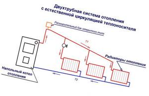
Boiler piping diagram with natural water circulation
Another point is the coolant supply section. It should be located on a slope. This does not in any way affect the wiring diagram of the electric boiler, but this is an important nuance in installing heating with natural coolant circulation.
Forced circulation piping
The pump forcibly pumps water, creating a slight pressure inside the system. This device is installed for one purpose - to evenly distribute the coolant over the radiators. Forced circulation is not used in all heating schemes.
If the house is small, then you can install the “Leningradka” scheme (it is also called one-pipe), in which the supply and return networks are mounted parallel to each other and next to each other. Radiators crash into them - only into the coolant supply network, in series.
Another option is called a two-pipe. This is when pipes are laid in the same way, but radiators are inserted into two flows at once: supply and return. The battery is connected to the supply section with one pipe, and the return pipe with the other. In the photo below the two options are clearly visible.
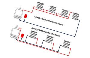
Heating system diagrams
Both schemes are closed. A hermetically sealed expansion tank is installed in them. Air cannot be vented through it. Therefore, the tank can be installed anywhere in the heating system. More often this is the return pipe next to the electric boiler. A circulation pump is also installed here if it is not included in the boiler unit design.
It turns out that the piping is two pipes that are connected to the boiler pipes. If heating is used with natural circulation of water inside, then an expansion tank is connected to the upper section through a pipe. If it is forced, then a circulation pump is additionally mounted on the return circuit. When the pump is already present in the electric boiler, then no other devices are installed except the expansion tank.
The only thing that is always present in the harness are two required elements:
- Supply pipe with a ball valve at the end. It is cut into the return line through a tee and connected to the water supply network. Purpose – to fill the heating system with water. You can additionally install a coarse filter here, which is usually done.
- Pipe for draining coolant from heating. It is equipped with a ball valve and connected to the house sewer. Purpose – draining water to free the heating network from the coolant for repair or dismantling.
Replacing the heating element
Replacing the heating element and other elements, as well as diagnostics to determine the cause of the malfunction, is carried out in a passive way when the electrical equipment is disconnected from the external alternating voltage source.
This issue cannot be resolved on your own if you are not an electrician and such work is carried out accordingly if you have knowledge of the regulatory documents of the electrical safety approval group.
So what is the need for these details? — You may ask, if in this or that case there is a malfunction, you can call the electrician directly.
Well, let's put it this way - knowledge of electrical and electrical engineering will not be superfluous for you.
Connecting an electric boiler
Let's consider connecting the EVAN S1-30 electric boiler to a four-wire, three-phase network with a neutral wire.
The fifth PE conductor in the diagram in Fig. 1 is grounding and is connected to the body of the EVAN S1-30 electric boiler. Reading the connection diagram:
The second branch from the same four buses is connected through a starter to the second contacts of the heating elements of two blocks.
Here it should be taken into account that for each individual block with heating elements, each individual heating element is connected to phase wires as follows:
Phase A and neutral wire N from the busbars are connected to the control panel. In its combination, the control panel is connected to a voltage of 220 V, the conductors from the control panel are connected:
The control panel consists of electronic elements that are not indicated in the diagram.
For electronic elements, diagnostics are outlined in this blog.
After carrying out repairs to replace one or another electrical part:
and other parts included in the electrical circuit, it is necessary, before connecting the electric boiler to an external source of alternating voltage, to check the electrical circuit of the boiler for resistance. Diagnostics of the resistance in the electrical circuit of this circuit is carried out either with an ohmmeter or a multimeter with the appropriate function.
If, as a result of measuring resistance, the device indicates a zero value, in this example you should reconsider the connections you have made. A zero resistance number indicates a short circuit in the electrical circuit.
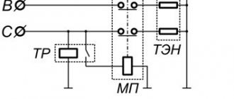
Consider the following electrical circuit for two types of boilers EPO-7.5 and EPO-9.45. The electrical circuit shown in Fig. 2 is identical and the difference here is only in the power of electric boilers. Let's follow the connection diagram:
These types of electric boilers are connected to a two-wire, single-phase network. The PE grounding wire is connected to the heating element block and to the body of the electric boiler. The phase wire from the phase bus in this circuit has a branching, one wire with phase potential goes to the control panel and is connected from the control panel to the first contacts of the heating elements,
the second wire with phase potential is supplied through the starter to the electric heating element; also from the starter, the wire with phase potential is connected in series through a switch to the control board. The control board has connections:
The neutral wire has a serial connection:
The connection diagram for the electric boiler Fig. 3 is intended for a two-wire, single-phase network. The power of electric boilers for this scheme is 5-6 kW.
The phase wire from the bus in a serial connection through the starter is connected to the first contact of the heating element. The neutral wire from the bus is connected to the second contact of the heating element. From the phase and zero buses, power is supplied to the control panel. Remote Control
The PE protective conductor is connected to the body of the electric boiler.
Electric boilers have only minor differences in their electrical circuits.
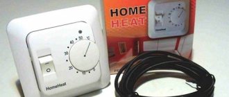
Current calculation
The RCD is selected taking into account the current strength. We substitute the values using the power formula,
We know two values from the formula - the power of the electric boiler and the voltage. From here we can find the current value.
The result of the current strength is known to you, all that remains is to select a protective shutdown device based on the calculated value of the current strength.
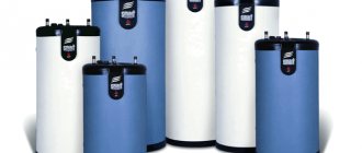
The Russian manufacturer /EVAN, which produces various types of heating equipment, including electric boilers, has already gained a positive reputation and is present in the sales of almost any large trading organization. The EVAN company has been known since 1997, first of all, for its affordable price with the traditional quality of products “made of metal, not just anything…”, which is very attractive to consumers. The company’s line includes not only the simplest electric boilers, but also higher-class devices...