Burner or oven?
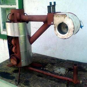
Homemade drip furnace in development
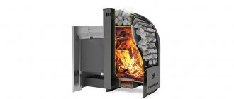
The problem of recycling used motor, transmission and hydraulic oil (waste oil) on a global scale is still far from being solved. One way to use waste is to burn it, receiving free heat. However, mining is an energy-intensive, but dirty and unstable fuel. Burners that allow the waste to be burned completely use pressurization, cleaning, dehydration and heating of the fuel, which makes them energy-dependent, technically complex and requiring qualified maintenance. Amateur craftsmen have been making exhaust furnaces with non-pressure burners for quite some time: in them, the oil burns quietly directly in the supply tank, evaporating, and the vapors enter the combustion chamber (afterburner), where they mix with secondary air and burn. Over the years of operation, mining furnaces with non-pressure burners have proven to be quite economical, but even more dangerous; comes to explosions. A drip furnace of the correct design is fireproof: evidence of this has passed accordingly. certification of industrial designs; Only domestic ones on the market include ZHAR-25 standard/automatic, semi-automatic NT 602-605, NT 612, VN-Zh-90-P/N, Teplamos T-603 (Teplon), etc. At the same time, the drip furnace is structurally simple and can be made completely non-volatile. Therefore, craftsmen are now working very closely on drip furnaces and are creating designs that are sometimes very intricate (see figure on the right). However, a good drip furnace can be made much simpler, and in terms of the efficiency of burning untreated water-flooded waste, it can come close to such a cunning device as a Babington burner.
What are the fuel requirements?
Any oil that has exhausted its service life is suitable as fuel: industrial, transmission and motor oil.
There are certain requirements and precautions that you need to be aware of before you start operating the unit:
- the mining should not contain impurities, even minor ones, as this may cause an explosion of the heating unit;
- A fire can be caused by ordinary water getting into the oil, which boils much faster than oil, and the splashes can ignite.
Important. Before pouring waste into the fuel container, it must be filtered. It is prohibited to use other flammable liquids as fuel. Gasoline for ignition is taken in very small quantities.
Why working off?
Drip fuel supply is widely used in heating engineering when a heat output of approx. up to 15 kW. The principle of operation of a drip furnace is simple: liquid fuel drips into a heated evaporator, into which primary air is supplied. Each drop evaporates and partially burns immediately, maintaining the temperature of the evaporator. The remaining fuel vapors enter the combustion chamber with the influx of secondary air, where they burn completely. Thus, in drip furnaces, 2-stage fuel combustion is carried out. Unlike stoves with non-pressure burners, where the fuel heats only itself until it evaporates, in drip stoves part of the heat from the combustion of each drop is spent on heating a rather massive evaporator, which determines their lower efficiency. But there are ways to minimize this disadvantage, see below.
The maximum power of a drip furnace is largely determined by the properties of the fuel: if, in order to obtain a given amount of heat, the fuel must be released in a trickle, the furnace becomes fire and explosive. Mining in this regard is good because its viscosity and surface tension are high, i.e. It is possible to obtain frequent and large drops of waste. Diesel fuel is significantly worse in these parameters, although it is still possible to make a stove using waste fuel and diesel, see below. Drip stoves are not made with light liquid fuel - it is dangerous. Fuel oil and oil sludge are too valuable as fuel, and industrial-scale sources of heavy fuels are too stable to be burned haphazardly.
Advantages and disadvantages of mining furnaces
Simplicity of design, low fuel consumption, ease of operation - these are the factors that make these heating units especially attractive. In addition to this, they have a number of other advantages:
- Effectively and quickly heat enclosed spaces.
- Does not depend on the availability of electricity or gas.
- You can use the oven for cooking.
- The dimensions and weight of the structure allow it to be transported if necessary.
- No open fire.
- The furnace allows you to burn waste oil and its vapors, and, subject to operating conditions, is not a fire hazard.
Despite the large number of advantages, this design has many disadvantages:
- The need to filter the oil, otherwise the impurities present in it may clog the supply tube.
- A chimney that is too high to create draft is required, more than 4 m high.
- High temperature of equipment surfaces.
- The chimney and stove have to be cleaned daily.
- Dirt in the room, noise during operation and an unpleasant odor.
- Possibility of fire if the combustion chamber is overfilled with waste.
- The heating unit goes out only when the fuel is completely burned.
IMPORTANT! You can start cleaning the oven only after it has completely cooled down.
Schemes of drip furnaces
Quite a lot of varieties of industrial devices for drip combustion of liquid fuel are known, and new patents appear regularly. But a home handyman and/or a car owner in an unheated garage shouldn’t rummage through them right away: it’s complicated, energy-dependent, and expensive.
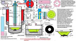
A drip furnace, available for hobbyist construction, can be built using one of the following. circuits (see figure):
- With a wick burner (the evaporator is filled with porous filler);
- With a “wet” bowl;
- With a flame (flame) evaporator bowl and bottom fuel supply;
- The same, with top fuel supply.
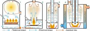
Schemes of the design of drip furnaces for mining
With wick
Any potbelly stove can be adapted for a drip stove with a wick burner, because It is not the falling drops of fuel themselves that evaporate, but its reserve in the hot porous filler. To start, a little fuel is poured into the evaporator, set on fire, and when the filler warms up (as can be seen from the boiling away of the remaining kindling and the appearance of a clean flame instead of a smoking one), drops are released. The power of drip furnaces with a wick evaporator does not exceed 6-8 kW, otherwise too frequent drops cool the filler and the furnace has to be started again. If the stove is left unattended, the excess drip will cause the evaporator to overflow and fuel will leak out; possibly burning. This is a serious disadvantage of drip wick evaporator ovens. Another is that they do not have the property of self-regulation; drops for testing from different batches must be set manually each time.
Filler
The efficiency of a drip-wick stove is largely determined, firstly, by the burner filler. The ideal option is fragments of animal bones; they retain all the dirt from the fuel. Thanks to a homemade stove with a bone-filled burner, an absolutely incredible story became possible.
During Robert Scott's famous Antarctic expedition, its northern party found itself cut off from its base on the eve of the Antarctic winter. Its participants were running out of food, matches, and fuel. There was no warm clothing or salt. People dug a cave in the snow and built a grease stove from a large tin can, but it worked poorly - it barely heated and consumed a lot of seal oil (blub). Then one of them, a simple sailor whose name deserves mention - Harry Dickason - came up with the idea of filling the evaporator with seal bones. The northern party in full force (6 people) survived the winter, and in the spring, on foot, pulling a sleigh, having covered almost 600 km, they returned to the base, where they were all considered long dead. One of the participants in the northern party, Raymond Priestly, wrote a book about this “Antarctic Odyssey” (Raymond Priestly, “Antarctical Adventures.” Keep in mind that you will suddenly find yourself in an extreme situation.
The filler made from fireclay brick crumbs has similar properties. Not fireclay mortar, but finely crushed brick. With it, the drip-wick furnace develops its maximum 8 kW, because The heat capacity of fireclay is high. Broken red working brick, moderately annealed brick, is somewhat worse, because less porous, and burnt iron ore bricks and clinker are not suitable. But any filler of an evaporative wick burner is quickly poisoned by dirt from the fuel, and it must be changed regularly.
Frame
The configuration of the body of a drip-wick stove does not greatly affect its efficiency: such a stove made from a potbelly stove will be very voracious. The ideal option here is an industrial gas cylinder, for example, oxygen; under a high, strongly convex arch, fuel vapors successfully burn out before exiting into the chimney. A drip stove made from an industrial gas cylinder is well suited for a garage due to its compactness. The outlet to the chimney (diameter 100 mm; height from 4 m) is made at a level of approx. 2/3 of the height of the cylinder. Leave 120-150 mm under the burner. At a level of 60-80 mm below its bottom, 12-16 holes with a diameter of 10 mm are drilled in a circle in the cylinder for air access, this is instead of a blower (the fire door must close tightly). A threaded hole is made in the bottom of the cylinder for a plug to drain condensate.
Note: the bowl and fuel supply system are the same as those of other drip stoves, see below.
With a wet bowl
For a wet bowl drip furnace to operate successfully, a pool of oil must be burning in its evaporator. In essence, it turns out to be a small stove with a gravity burner, fed drop by drop, releasing vapor into a large afterburner. However, its efficiency is worse, because part of the secondary air (entrained by the flame in the bowl) slips into the chimney, carrying oil vapor with it. Whether the chimney is on top or on the side does not matter in this case. In addition, primary air flows around the evaporator bowl, cooling it.
The advantage of this furnace is some ability for self-regulation. If the flame in the bowl gets too hot, it will also reduce the flow of secondary air into the afterburner. Since quiet burning of oil in a bowl requires little air, the flow of primary oil will decrease and the flame will subside. But the limits of self-regulation are small, and when switching to testing from another batch, the dropper (see below) needs to be reconfigured.
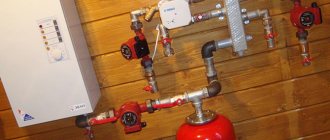
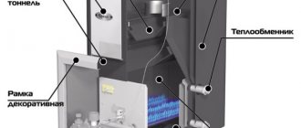
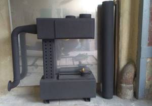
Homemade drip stove with forced circulation air heating circuit
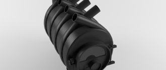
Another advantage of this furnace is the ability to integrate a horizontal air heat exchanger into it. The stove, pressurized by the air heating circuit from a low-power fan, turns into a heater (see figure on the right). Unfortunately, a vertical non-volatile heat exchanger with natural circulation cannot be installed: it will disrupt the afterburning process, and the furnace will soon become overgrown with carbon deposits (coked).
And finally, the optimal size and shape for an 8-10 kW oven of this type is a 50 liter household gas cylinder. Due to these advantages, drip furnaces with a “wet” bowl have recently become popular due to their simplicity of design.
Note: the low maximum power of furnaces with wick and wet bowl is also explained by the fact that the oil in them can evaporate in the supply tube, the end of which is located close to the flame. The vapors will evaporate into the afterburner and burn, there will be nothing left to heat the bowl, and the stove will go out.
With a flaming bowl
The most economical and safest type is a drip-type furnace with a flame bowl. The features of its structure and operation are as follows:
- Air is supplied from above through air duct B, which passes vertically through combustion chamber K.
- Secondary air (although physically in this case it is primary) is immediately taken away by fuel vapor for afterburning.
- Primary air (physically secondary) enters directly into the fuel flame in the evaporator, bypassing the bowl.
- Fuel vapor enters the combustion chamber through the annular gaps in the diaphragm D.
- It is possible to supply fuel from above through a supply tube located coaxially in the air duct, which eliminates premature evaporation of the fuel.
Thanks to these features, drip furnaces are, firstly, self-regulating: the evaporator got too hot - more vapor was spent on afterburning - less air got into the bowl - the furnace returned to mode. Secondly, it is less sensitive to the properties of the fuel: if you get oil that is more fluid, the drops start to drop more often and the evaporator flares up - see above. The oil was watered - the oil vapors, being heavier, pushed the water vapors to the periphery - the water vapors went into the peripheral gap and into the chimney, without disturbing the combustion process. We filled the tank with diesel instead of oil - the fuel vapor went to afterburning through both gaps - the combustion chamber consumed more secondary air - the flame in the evaporator died down - the stove returned to mode. And thirdly, a furnace with a flame bowl and top fuel supply is capable of developing the maximum power for this class of devices, up to 15-16 kW, thanks to air cooling of the fuel supply line.
Fuel from below
A drip furnace with a flame bowl and bottom fuel supply is structurally simpler and, unlike furnaces with wick and wet bowls, is capable of developing power up to 10-12 kW due to wider self-regulation limits. An evaporation bowl can also serve simply under a stove if it is installed on a fireproof floor or on legs; in both cases, on a gasket made of asbestos or basalt cardboard with a thickness of 20 mm or more.
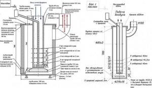
An assembly drawing of a drip furnace with a flame bowl and bottom fuel supply, dimensions and details for it are given in Fig. Material: pipes of different diameters. The bowl is under the stove. The peculiarity of this design is that it is not critical to the overall dimensions. When the height of the perforated part of the air duct increases from 350 to 500 mm, the furnace power increases from 6 to 9 kW. Further increasing the height of the furnace body increases its efficiency without increasing power. The oil tank is also made from a 90 mm pipe. The fuel from it is supplied to the dropper through the side pipe, and the bottom one is designed to drain the accumulated sludge.
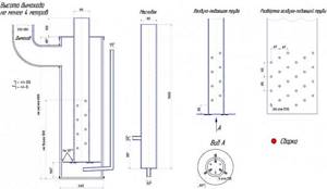
Drawings of a drip furnace for testing with a flame bowl and bottom fuel supply
Fuel from above
The top supply of fuel to a drip furnace with a flame bowl allows it to realize the maximum possible power and efficiency. The reason is that the self-regulation range of this design, which is the largest for drip furnaces, makes it possible to organize a proportional supply of secondary air: holes in the air duct are drilled in horizontal rows, and their number in a row and, possibly, diameter are reduced in height. To ensure high efficiency of the furnace at the lowest stroke, the lower row of holes is sometimes replaced by vertical slots. In this way, an air flow into the combustion chamber is organized, exactly equal to the need for it from burning fuel vapors at different operating modes of the furnace.
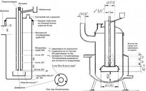
Drawings of a drip furnace in production, in which the above principles are implemented, are shown in Fig. This is the same stove, just depicted differently. Excluding the chimney and the bottom of the bowl: the option on the right is designed for 40-60 W fan pressure. The efficiency of this furnace will be only 3-4% less than that of a Babington burner if it (the furnace) is equipped with an air jacket with natural circulation, thus turning it into a heater furnace. The air in the jacket, when heated, will not diverge to the sides, but will create thermal insulation, improving the conditions for burning fuel vapors. The thickness of the air layer in the jacket is 100-120 mm.
Drawings of a drip furnace with increased power and increased efficiency
From cylinders
A 50 liter household gas cylinder is also quite suitable for the body of a drip furnace for mining with a flame bowl. Moreover, its large relative width and convex arch make it possible in some cases to abandon the diaphragm, which requires extra metal, work and complicates the maintenance of the furnace. True, it will not be possible to accelerate a drip furnace from a cylinder to more than 11-12 kW, but since any furnaces in production are suitable for heating only non-residential premises, this is not so significant.
Drawings of a drip furnace from a cylinder with a flame bowl and top fuel supply for air heating are given on the left in Fig. below. Please note: the holes in the duct are narrow; There are only 3 rows of them, located far apart in height. In a wide cylinder, burning gases rise more slowly than in a pipe and therefore mix with air better, but not yet well enough. Strong streams of air shoot out from the holes in the air duct, further mixing the gases. In the bottom row, the holes are frequent, streams of air from them form something like a virtual diaphragm, which works in the same way as the steel one in pipe furnaces.
Drawings of drip furnaces for exhaust from a household gas cylinder
On the right in Fig. – drawing of a drip furnace with a water jacket from a household gas cylinder in production. Water greatly cools the combustion chamber, preventing fuel vapors from burning out properly. Therefore, here all the secondary air “splashes out” all at once into the zone of greatest concentration, at the same time forming a virtual diaphragm stretched in height from many wider and weaker streams of air. Actually, the result is no longer a virtual diaphragm, but a virtual piston of variable diameter. This is worth a slight decrease in the efficiency of the furnace compared to the previous one, but attaching a water jacket to a drip furnace without reducing its efficiency to an outrageously low level is actually a very difficult matter.
Drip boiler
On the trail. rice. Given as an example are drawings of a drip water heating boiler from the same cylinder during testing, suitable for CO with forced circulation of the coolant (in the previous case it can only be natural thermosyphon). As you can see, the whole range of measures has been applied to increase the efficiency of the drip furnace, plus thermal insulation of the bowl and jacket with basalt wool. The insulation, in turn, must be carefully isolated from fuel vapors, otherwise the boiler will quickly fail. The sources of waste are unstable, the design of the boiler is complex, and therefore this sample has not received any widespread use.
Drawings of a drip water heating boiler for testing
Installation of a furnace operating on waste oil
A foundation for such a stove is not required, since the structure is very light, but the surface on which the stove is installed must be strictly horizontal. Install the stove in such a way that it is convenient to fill in fuel. For ease of filling fuel, use a funnel (watering can). If the floors are wooden, then before installing the stove, a metal sheet is laid on the floor.
Among the important aspects regarding the design are the following:
- the internal diameter of the chimney must be at least 10 cm, the wall thickness must be at least 1 mm;
- steel thickness for tanks - 4 mm, for the bottom of the firebox and the lid of the upper tank - 6 mm;
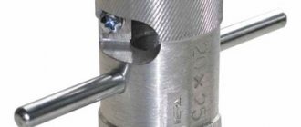
- the length of the burner must be greater than its diameter;
- the optimal volume of the tank intended for fuel is from 8 to 15 liters;
- pipes are selected from materials such as: stainless steel, copper, painted tin;
- the chimney must be able to be dismantled for ease of servicing the stove;
- an inclined position of parts of the chimney located indoors is allowed (to improve heating of the room), however, outside the room the pipe must be strictly vertical (to prevent wind from blowing).
What you need for work
- drawing;
- welding machine and electrodes;
- grinder, cutting wheels for metal, file, sandpaper;
- steel corners or fittings;
- set of drills and drill;
- steel sheets 4 and 6 mm thick;
- pipes for the chimney and burner;
- hammer;
- roulette and level.
Preparing and assembling the furnace (drawing)
- We print out the drawing and begin preparing for assembly. We connect all the parts using a welding machine. An exception is tank elements marked “tight fit” on the drawing. We make them collapsible. We carefully check all welds for leaks. We clean off the scale with a grinder or file.
- We lay out the sheet steel on a flat surface, make markings and cut the parts with a grinder. We perform bending on a sheet bending machine, preparing parts - tank walls. We check the tightness of the parts.
- On the left in the photo is the finished lid of the lower tank, on the right is its lower part. We do not weld them together; the parts should remain collapsible, but fit tightly to each other. The hole for pouring fuel into the stove is about 5 cm in diameter.
- We assemble the upper tank (weld the walls to the bottom).
- We weld a baffle partition in the upper tank (closer to the burner hole). Attach the exhaust pipe. We will subsequently connect the chimney to it.
- On the pipe intended for the burner, we drill 48 holes with a diameter of 9 mm each. We connect the upper chamber and the burner by welding.
- Checking the dimensions of the parts. We install the sealing ring.
- We weld a tank designed for filling oil. We equip it with an overflow pipe.
- We cut out three legs 20 cm long from a metal corner and connect them to the bottom of the oven.
Making a waste oil furnace with your own hands - video tutorial
Some parts of this stove can be cut from a thick-walled pipe or a used gas cylinder. But if there are no cylinders, there is no possibility or desire to bend the metal into a radius, you can mount a similar oven, but with a square cross-section
. Cutting out the parts of this design is much easier. If you don’t have a grinder, we use guillotine shears for metal.
- Let's prepare the lower part of the oven. To do this, we connect together the legs, bottom and side walls of the fuel tank.
- The upper part of the firebox must fit tightly onto the lower part. We carefully check the dimensions of the walls before cutting the metal. We attach the fuel tank cap to a screw or steel rivet to make it possible to rotate the cap if necessary.
- We install a partition in the upper tank.
- We weld the pipe that will be connected to the chimney.
Since the chimney will have several sections with a slope of 45 degrees, we install special bends at the junctions of the pipes. Where the pipe passes through the ceilings, we additionally line it with non-flammable materials (mineral wool) and a layer of metal (in hardware stores, a special “roof passage” element is sold for this purpose, facilitating installation). In addition to bends, clamps and a metal mushroom are useful to prevent rain and snow from getting inside the pipe.
We finish here, we advise you to read an article about how to build a bubafon oven with your own hands, because its design resembles what we reviewed yours.
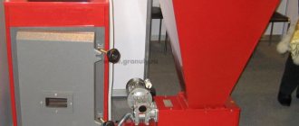
Fuel supply
Amateur craftsmen often supply drip furnaces with single-stage fuel: an oil tank, a ball valve, and a supply tube. Firstly, this is dangerous: for convenience and safety of starting the stove, the valve must be placed closer to it. The supply tube gets quite hot when fuel is supplied from the bottom. If the heating passes through the pipe past the valve, up to which there is a solid column of fuel in the pipe, this could lead to disaster. Secondly, the fuel supply to the furnace is unstable: as the tube warms up, the drops become more frequent, because the oil thins out. If it flows in a trickle, then it is again dangerous.
The drip supply of oil to the furnace during processing should be organized according to a 2-stage scheme: main (storage) oil tank - valve - supply dropper - supply tank (tank) - free flow from it at least 60 mm from the bottom (for additional sedimentation of sludge) - working dropper. The fuel supply is opened when the kindling in the bowl (see below) is lit. While the oil drips into the tank to the level of the drain, you can slowly adjust its flow, and then it drips into the bowl drop by drop.
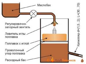
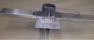
Scheme of safe power supply of a drip furnace from a supply tank with a safety valve and capillary
This system, however, is not completely safe. If in a hurry, out of ignorance, or simply trying to quickly warm up from the cold, open the valve too much, the consumables will immediately fill, fuel will rush into the stove, and it will throw out a tongue of fire and start spitting burning spray. It would be correct to build a drip oil supply system into the furnace with a safety float valve and a metering capillary (see figure on the right).
Since different metals are wetted by waste in different ways, and its properties vary significantly from batch to batch, the length of the capillary will need to be selected: the oil is fed under a gravitational pressure of 120-150 mm (from a suspended container) at room temperature, and the capillary is selected so that it drips more often, but with drops clearly visible to the eye. A diesel fuel drip furnace can be used from the same feeder, but the capillary will need to be taken with a clearance of 0.6-1 mm and a length 2.5-3 times longer than for mining. There is only one drawback to this scheme for supplying fuel to a drip furnace: the exhaust is dirty fuel, and the capillary will have to be cleaned periodically.
Note: if you are not lazy and make a supply tank with replaceable capillaries for different oils and diesel fuel, the stove will become multi-fuel.
How to make a waste oil boiler with your own hands
The simplicity of the design of such heating devices allows you to make them yourself. In this case, it is necessary to have metalworking and welding skills.
Tools and materials
To make a boiler with your own hands, you need the following equipment:
- Bulgarian;
- welding machine;
- hammer.
To make a waste oil boiler with your own hands, don’t forget the grinder
As a material for the heating structure, you must purchase:
- fire-resistant asbestos sheet;
- heat-resistant sealant;
- steel sheet 4 mm thick;
- metal pipe with a cross section of 20 and 50 centimeters;
- compressor;
- ventilation pipe;
- sweeps;
- bolts;
- steel adapters;
- half-inch corners;
- tees;
- reinforcement with a cross section of 8 millimeters;
- pump;
- expansion tank.
The boiler body for heating small rooms can be made of pipe; for a device with a higher power it is best to use steel sheets.
Manufacturing process
The waste oil unit can be built in any shape. To heat a garage or small agricultural buildings, it is best to make a small boiler from pipes.
The manufacture of such a heating device consists of the following steps:
- A metal pipe with a large cross-section is cut so that its size corresponds to one meter. Two circles corresponding to a diameter of 50 centimeters are prepared from steel.
- The second pipe with a smaller diameter is shortened to 20 centimeters.
- A hole corresponding to the size of the chimney is cut out in the prepared round plate, which will serve as a cover.
- In the second metal circle, intended for the bottom of the structure, an opening is made, to which the end of a pipe of smaller diameter is connected by welding.
- We cut out a cover for a pipe with a cross-section of 20 centimeters. All prepared circles are welded as intended.
- Legs are constructed from reinforcement and attached to the bottom of the housing.
- Small holes are drilled in the pipe for ventilation. A small container is installed below.
- An opening for the door is cut out in the lower part of the body using a grinder.
- The chimney is attached to the top of the structure.
To operate such a simple boiler during mining, you just need to pour oil into the tank from below and set it on fire with a wick. Before this, the new structure should be checked for tightness and integrity of all seams.
Construction of a more powerful boiler
Two boxes are made from durable steel sheets, which are connected using a perforated pipe. In the design it is used as an air outlet.
The subsequent manufacturing process of the heating device has some features:
- A hole is made in the lower body of the boiler to supply oil to the evaporation tank. A damper is attached opposite this container.
- The box located in the upper part is complemented by a special hole for the chimney pipe.
- The design is equipped with an air compressor, an oil supply pump and a container into which fuel is poured.
DIY waste oil boiler
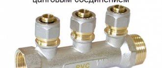
If water heating is required, an additional circuit is connected, which requires the installation of a burner. You can build it yourself:
- half-inch corners are connected by bends and tees;
- a fitting is attached to the oil line using adapters;
- all connections are pre-treated with sealant;
- a burner cover is cut out of sheet steel to match the sockets on the manufactured boiler;
- two different sized steel plates are used to install the burner;
- the inside of the tube adapter is tightly covered with an asbestos sheet, which is secured with sealant and secured with wire;
- the burner is inserted into the housing intended for it;
- after this, a smaller plate is fixed in the socket and covered with four layers of asbestos;
- a large plate is mounted as a mounting plate;
- holes are drilled in it for fastenings, and an asbestos sheet is applied on top;
- two prepared plates are connected using bolts.
To prevent the burner from falling apart while the boiler is operating, all parts should be carefully and tightly secured. The device is ignited by a glow plug.
Waste oil boilers are considered economical and practical devices. You can purchase them at a specialty store or build them yourself. When using such heating devices, you must remember the safety rules, which include the mandatory installation of a chimney, the presence of a ventilation system and proper storage of liquid fuel.
Starting the furnace
It has already been said implicitly that you need to start the drip furnace slowly and smoothly. Usually, for this they use a torch made from a knitting needle with a piece of foam rubber or a rag: let some drops in and place the torch. When it gets wet, they wait until a puddle drips into the bowl, light a torch, and pour oil into it.
There is a much more convenient and safer way to start a drip stove: a wad of toilet paper soaked in the same oil. They put it in a bowl, set it on fire and slowly regulate the drips, no longer worrying about kindling. Toilet paper is almost pure cellulose; it burns without leaving a residue. Tourists have been warming themselves in tents this way for a long time: the roll is inserted into a wood chip stove, poured with half a glass of alcohol (which also burns without a trace), or the whole thing, darling, and set on fire from above. A lot of heat is generated, and an insignificant amount of fluffy ash can simply be blown out. In the oven it will fly out into the chimney.
Why recycle machine oil?
Abroad, especially in the United States, the technology of converting waste engine oil into diesel fuel is not something new. Moreover, this is a long-used technology and proven practice that allows you to use previously unnecessary substances and increase the level of ecology. This approach also helps strengthen the economy.
Where does diesel go after used oil is recycled? Firstly, some vehicles run on diesel because it is cheaper. Secondly, it is actively used in construction and when laying railway tracks.
Such a substance is capable of maximally protecting the material, especially wood, from external aggressors in the form of insects and environmental factors.