Modern technology copes with solving almost any problem related to room ventilation, doing it at a high level. Working conditions in production premises can be fully ensured in accordance with the requirements.
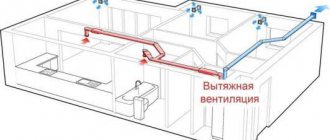
Modern comprehensive equipment is also installed in residential buildings and buildings, as well as commercial areas, providing a comfortable environment. Exhaust ventilation successfully removes waste air. Moreover, at production facilities it is capable of performing targeted removal of harmful contaminants. And in residential interiors it functions as part of the overall complex system.
The need to install control units
Supply ventilation system installations, in accordance with the basic requirements of regulatory documents, must supply fresh outside air, preheated to a certain temperature. The supply air temperature must correspond to the type of ventilated room in the case of general ventilation or the technological process in the case of any production cycle.
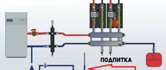
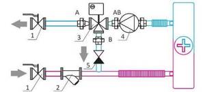
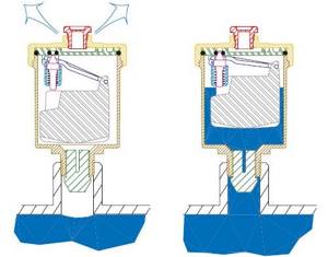
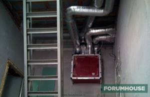
The principle of operation of the supply and exhaust ventilation system.
In addition, the air temperature must be constant regardless of the outside air temperature and adjustments to the coolant temperature schedule. That is, when it gets colder and the temperature outside decreases, heating networks, as a rule, increase the temperature of the coolant, and the air temperature at the outlet of the air handling unit must remain at a given level.
Consequently, the heat load during the heating period is not a constant value, and the coolant must be regulated. Otherwise, there will be excessive consumption of thermal energy, an increase in temperature and excessive overheating of the premises, which can adversely affect the well-being of people or the technological process.
The air is heated in air supply air heaters, the number of which may vary depending on the adopted heat supply scheme. The most common option is installations with one heater, but there can be two or more.
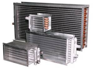
Heaters are designed to heat air in the supply and supply and exhaust ventilation systems.
For some institutions where air heating is also necessary during the transitional season, two separate circuits of the heat supply system are provided. One heater operates in spring and autumn, the second circuit in winter. In the event of extreme frosts, when the main heater cannot cope with the load, the second one can heat the air to a predetermined temperature.
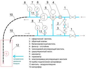
Supply installation of ventilation system.
Also, one of the main advantages of this scheme is almost 100% redundancy of the heat transfer surface. In case of emergency situations when one heater fails or defrosts, the second heater will be connected to operation and will fully cope with the main function. Therefore, when calculating the installation, it is advisable to provide two identical heaters, with a surface corresponding to the maximum power of the two operating modes.
When calculating the air handling unit, you may encounter a situation where the selected heater in maximum mode will produce thermal power many times greater than the required one. This is due to the limited number of heater sizes available from the manufacturer. Therefore, in order to have a constant supply air temperature, it is necessary to install control units of the heat supply system on each heating circuit and at each installation. These units will be controlled by the automation system of all ventilation systems of the complex.
Forced system with recuperator
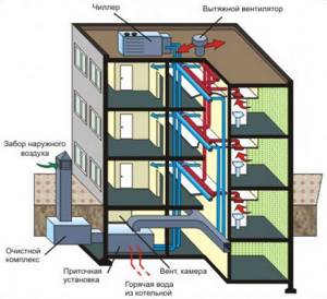
Forced ventilation with a recuperator is the most advanced system capable of circulating air flows in specified modes and volumes. Its operation involves minimal energy consumption. After all, the flow from the street is first heated by the recuperator (due to the heat contained in the exhaust air), and then the air is additionally heated to a temperature comfortable for humans. In many developed countries, such a technical solution has already become a construction standard enshrined in legislation.
Taking into account the growing requirements for the comfort of residential premises, it is advisable to equip any new house not just with standard ventilation ducts, but with a multifunctional and economical forced ventilation system. A recuperator-based system provides a supply of clean air at a comfortable temperature and simultaneously removes waste air masses outside the room. At the same time, heat (and sometimes moisture) is selected and transferred from the exhaust flow to the supply flow.
Classification of power control options for installations
Scheme No. 1
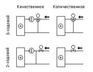
The supply ventilation heat supply system can operate in several fundamentally different control modes:
- If during the operation of ventilation systems there is a smooth or stepwise change in water temperature at a constant flow rate, then it is customary to say that high-quality regulation is used at this unit. It is used in boiler houses or in individual heating points, that is, changes in coolant parameters will occur directly throughout the entire heat supply system. The hot water temperature is adjusted according to a special schedule of the heat supply organization depending on changes in the outside air temperature.
- If a change in the heat load occurs when the amount of coolant entering the installation changes, that is, at a constant temperature, the flow of hot water changes smoothly. Here we are dealing with quantitative regulation.
- With the qualitative-quantitative control method, temperature adjustments occur in the heating system (or from a heat source) and coolant flow changes zonally at each installation in its own mode. A rather complex control method, but most widely used in ventilation heat supply systems. It can only be implemented when installing an automation system.
Video description
More about ventilation calculations in the video:
Ssection = V * 2.8/w, where Ssection is the cross-sectional area, V is the volume of air mass (m³/hour), w is the speed of air flow inside the highway (m/sec) (average from 2 to 3), 2, 8 – dimensional matching coefficient.
For installation, it is necessary to calculate how many diffusers (intake and outlet openings) and their parameters are required. The dimensions of the nozzles are calculated based on the cross-sectional area of the main pipeline, multiplied by 1.5 or 2. To calculate the number of diffusers, use the formula: N=V/(2820 * W * d2), where V is the volume of air mass consumed per hour, W is speed of movement of the air mass, D – diameter of the round diffuser.
For rectangular diffusers, the formula is transformed as follows: N=π * V/(2820 * W * 4 * A * B), π is the number pi, A and B are the section parameters.
In any case, calculations of ventilation systems should be carried out by professionals - if something is forgotten or not taken into account, then the cost of the mistake is the need to redo the calculations and work.
A full calculation of supply ventilation is done using specific software Source ventisam.ru
Basic diagrams of control units
Scheme No. 2
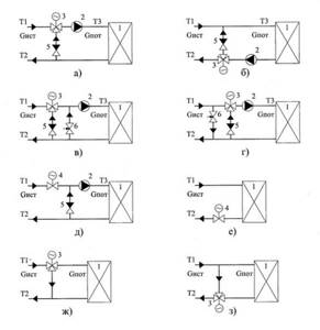
There are at least several basic heater piping schemes, which have fundamental differences in terms of the chosen control scheme and heat supply source. There is no clear answer as to which of the schemes described below is correct; it all depends on a large number of factors (heat supply source and its capabilities and coolant requirements, already installed network equipment, the value of the free pressure drop at the entrance to the building, etc.).
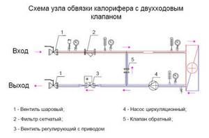
a two-way linear control valve is installed as a control element , which absorbs the excess difference at the connection point and performs the main function of limiting the flow of water through heater. But in order to ensure protection against freezing of the air heater, a circulation pump is installed on the internal circuit of the air heater, which ensures constant flow through the installation through an additional jumper. This is a classic method of quantitative zonal control at each air supply unit.
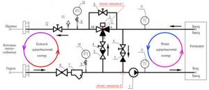
Scheme No. 3
No less common are heat supply schemes for heaters with installed three-way valves . These circuits can operate in different control modes depending on the position of the valve and the location of the jumper insertion.
Scheme No. 4
Three-way valves can operate in water flow separation mode or as a mixing element (diagram No. 4). If the valve is installed in such a way that, depending on the heating demand of the installation, port A (from the heating network side) opens or closes, and the coolant circulates through the clan bypass (ports B and AB), then the most common quantitative control scheme takes place. Its use, as a rule, is limited by the maximum pressure drop in the central heating system, therefore it is most often used in autonomous heating systems. But when designing such a scheme, it is necessary to take into account that the flow rate in the heat supply system or at the heat source is not constant, therefore the network pumping equipment must be equipped with frequency converters.
Scheme No. 5
If it is necessary to ensure a constant flow rate from the heat source, then a jumper with an installed check valve and balancing valve should be added to the previous diagram in front of the valve (diagram No. 5).
If the jumper and valve are swapped in the circuit, and water is circulated in the internal circuit through the jumper, then the pressure of the circulation pump in this case will be less by the amount of hydraulic resistance of the valve. The coolant flow from the heating network will remain constant, and the valve will operate on a free pressure drop (diagram No. 6).
Scheme No. 6
Basic equipment of heat supply units. Selection and calculation
The heat supply units of air handling units made according to different schemes, as a rule, include identical equipment. Such units differ only in the installation location, the saturation of the reinforcement and the selection method.
When selecting equipment for heat supply units, there are several general rules and recommendations:
- When choosing a particular type of valve, you should carefully check the technical characteristics of both the maximum operating pressure and the maximum temperature.
- It is highly not recommended to purchase ready-made mixing units that are selected based on average conditions without taking into account important parameters such as free pressure drop in the system, type of coolant, flow rate, type of heat source, the need for frequency regulation, and so on.
- The diameter of shut-off valves, as well as check valves and mud traps must be no less than the diameter of the pipelines.
- The diameter of the heating system pipelines is determined as a result of hydraulic calculation based on the calculated (required) coolant flow rate, type of coolant (water or low-freezing liquids) and pipeline material. In no case should the diameter of the heating supply units be selected based on the connecting ports of the heater. It is selected ONLY BY CALCULATION!
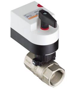
Shut-off valves
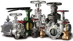
It is necessary to shut off the water flow in cases of emergency stops of the heating system, for example, to eliminate a leak, to carry out service or inspection work, etc. As shut-off valves, steel or brass ball valves (preferably full bore) or flanged valves are used.
For heat supply units with a pipeline diameter of up to 40 mm inclusive, it is customary to install threaded shut-off valves, and flanged valves over 50 mm.
To facilitate the installation or dismantling of assemblies, threaded fittings should be provided with union nuts, otherwise called “American or socket nuts”.
Check valves
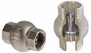
Check valves are used in control units to prevent water from flowing back into the heating system if control valves are opened or closed. Or this is possible when the heating system is not balanced, a large number of units are installed in the system and when the coolant flow changes, pressure may occur on each other. Therefore, check valves are installed on the return pipeline and on the jumper of the heating supply unit.
Control Valves and Actuators
Two way valve.
A two-way or three-way control valve is the main actuator, which, by changing the flow rate or by mixing coolants, allows you to regulate the power of the air-handling unit heater depending on the heating demand of the installation. Another important function of the valve is to prevent the coolant from “freezing” when the units operate in winter. When the automation receives a signal about the critical temperatures of the coolant and air after the heater, the drive opens the control valve to the maximum flow.
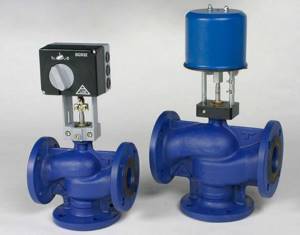
Three-way valve.
The valve is selected based on the determination of the throughput coefficient Kv, which means how much coolant flow will pass through the valve in the open state with a loss of 10 meters of water column.
,
where G is the estimated water flow, m3/h; ∆p - actual pressure drop across the valve, bar Ƥ - coolant density.
The size of the control valve cannot be selected according to the diameter of the pipeline or heater ports. The smaller the Kv or valve diameter, the higher the speed of response to changes in air or heating network parameters will be, that is, the system will not be inertial.
In heat supply systems of air supply units, as a rule, two and three-way valves are used. Two-way valves work only in systems with changes in coolant flow, and three-way valves either act as mixing valves or work to separate heat flows.
Measuring fittings: pressure gauges and thermometers
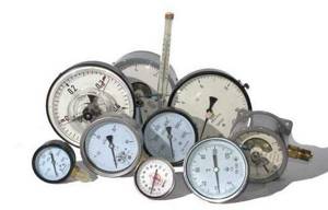
Measuring equipment
Pressure gauges and thermometers are necessary tools for visual monitoring of the performance of the heating system. Thermometers are usually installed on the supply and return pipelines directly next to the heater. Pressure gauges are mounted on the pump group to monitor the operation of the pump and visually determine the difference created. Pressure gauges are also installed before and after the sump tank - to determine the degree of its clogging, and on the supply and return pipelines of the heating network in front of the piping unit - to control the free drop necessary for the full operation of the control valve.
Air bleed valves and system drain taps
Automatic air release valve
To bleed air after filling the system and during operation, it is recommended to install automatic air bleed valves in the piping units. They are conveniently mounted on special ports embedded in the heater coils in the upper part of the housing or at the highest point of the control unit pipelines.
Taps for emptying heaters and draining a section of the heating system should be installed at the lowest point of the control unit, or at the bottom of the heater.
Balancing valves
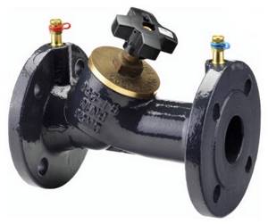
Balancing valve
If the heat supply system has several air supply units operating in their own independent mode, then the heat flows in the pipelines will not be constant and may differ significantly from each other. To prevent pressure on each other from the coolant side, balancing valves are provided. Their main and main function is to throttle excess pressure and equalize the distribution of water flow between heaters in accordance with needs. Balancing valves installed on the return pipelines hydraulically link the heaters to each other.
The selection of valves is carried out by analogy with the selection of control valves, taking into account the Kv coefficient. The initial data for determining the valve size is the excess pressure drop that the balancing valve must absorb and the calculated flow rate in the network section.
Circulation pump
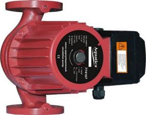
Circulation pump
The circulation pump of the internal circuit of the piping unit is designed to ensure constant circulation of water in the heater. This will minimize the risk of the heater “defrosting” at low outdoor temperatures. But the main purpose of the pumps is to overcome hydraulic resistance in the regulated area, that is, on all functional elements of the mixing unit, unloaded from the pressure of the heating network.
The regulated section usually means a heater, pipelines, shut-off and balancing valves, check valves and a sump. The control valve may be part of the regulated section, depending on the adopted heater piping scheme. If the control valve is installed in the piping unit in such a way that the coolant circulates in the internal circuit through the jumper of the valve itself with the direct port closed, then the valve is part of the circulation circuit. In such cases, the pump pressure is determined as the sum of the hydraulic resistance of all elements of the regulated section. It should be remembered that in the case when the coolant in the heating system is not water, the hydraulic resistance of all elements of the regulated section and the calculated flow rate should be adjusted depending on the viscosity and density of the coolant. Hydraulic losses on mud pits should be taken into account with a margin of 50% clogging.
If the control valve operates on a difference in the heating network (diagram No. 3), then the pressure loss on the valve is not taken into account when calculating the pump head.
When calculating the friction resistance of pipelines, it is imperative to take into account all pressure losses at branches, corners and turns. It is also necessary to take into account the roughness of the pipeline walls in accordance with the selected material.
All pressure losses on the elements of the piping unit should be determined only at the operating flow rate of the coolant, and not in accordance with the maximum flow rate of the heater that it is capable of passing.
The selection of circulation pumps is made according to the technical catalogs of manufacturers in accordance with operating points (calculated water flow and required pressure). The most common type of pump in units are three-speed glandless pumps. In cases where a smooth change in flow rate in the supply ventilation circuit is required, pumps with a built-in frequency converter are used.
Sump
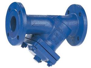
Sump
Mud filters are filters for mechanical cleaning of coolant, usually with a mesh size of about 500 microns. In old heating systems, heating water contains a lot of suspended particles, sand or scale. All these contaminants can damage control valves and circulation pumps. Therefore, installing mud collectors directly in front of the equipment is a prerequisite for maintaining operability and warranty.
Additional selection criteria
When choosing a recuperator, it is important to pay attention to the noise level it creates during operation. This indicator depends on the material from which the device case is made, on the thickness of the case, on the power of the fans and on other parameters.
According to the type of installation, recuperators can be suspended (mounted on the ceiling) or floor-mounted (installed on a flat horizontal surface or hung on a wall). Exits for ventilation ducts can be either on both sides (“through” layout) or on one side (“vertical” layout). Which recuperator you need depends on the specific parameters of your ventilation system and on where exactly the supply and exhaust equipment will be installed.
Protection of heaters from defrosting. Coolants in ventilation systems
The number and purpose of air heaters in supply ventilation installations may vary depending on the composition of the installation and the purpose of its operation. The heaters can be of first heating, second heating, with preheating in front of plate recuperators, separate for operation at different times of the year, or used for heating on separate branches of air ducts if the temperature conditions of the served premises are different.
Therefore, it is customary to say that preheating or 1st stage heaters always operate on “hot” air. That is, air with a very low temperature enters the heaters. In a continental climate, the danger of heaters defrosting is very high when starting up installations in winter or during new construction, when there are frequent interruptions in the power supply and interruptions in the supply of hot water.
There can be a huge number of reasons for water freezing in heaters in winter: from accidental closing of the valve at the inlet to a failure in the power supply and automation systems. Also, the most common cause of defrosting is the incorrect choice of circuit, low pressure drop in the heating system, incorrect selection of the control valve and a drive with a long response time.
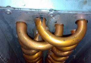
Defrosted heater of the supply ventilation system
You should also know that the ideal choice for controlling control valves is an actuator with analog control using a 0-10V signal. An equally rare cause of system defrosting is uncoordinated operation of the supply and exhaust ventilation systems. For example, it is a common case that during non-working hours the air supply units are switched off, but the exhaust units continue to operate for some reason, and a vacuum of air is created in the building. To replenish the air balance, air begins to be sucked in through all available leaks, including through a leaky air damper. Thus, when the system’s automation and insensitive sensors are turned off, the signal about low temperatures does not issue a command for the automation to turn on the heating of the heating system and the water in the heat exchanger freezes.
Video on defrosting the heater of the supply ventilation system:
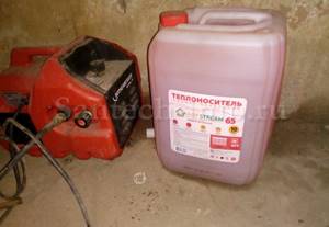
Of course, heater piping units must also be equipped with the required number of sensors and protective thermostats complete with control cabinets, but in the event of power surges or lack of power supply, the automation system will not be able to protect the heaters. The only option to protect the system from defrosting with a 100% guarantee is to fill it with low-freezing coolants.
The main advantages of antifreeze include a low crystallization temperature and the absence of thermal expansion in a frozen state, which does not lead to rupture of the walls of air heaters. Low-freezing liquids include sets of additives that protect the pipeline system from corrosion, minimize cavitation and prevent sediment from forming when the system heats up or cools down.
The use of low-temperature coolants in some heat supply systems is limited by a maximum maximum temperature of 95-100°C, above which the chemical composition will decompose. Therefore, in an individual heating point, a temperature regulator or valve should be installed on the media separation heat exchanger (water-NZT), which will protect the heating system circuit from increasing the temperature above the critical one.
In heat supply systems, as a rule, ethylene glycol or propylene-glycol mixtures are used, which differ in both price and scope. Ethylene glycol is the cheapest coolant, therefore it is most widely used in engineering systems. Propylene-glycol mixtures are used in safe industries, where in the event of system depressurization, a toxic coolant can pose a potential threat to life or disrupt the technological cycle. Such requirements are found mainly in the food industry or in medical institutions.
A low-freezing coolant with a crystallization temperature of -30°C contains 40% ethylene glycol mixed with distilled water. The main feature of all ethylene glycol-based coolants is the formation of a plastic gel at low temperatures, which does not cause rupture of heater tubes or the formation of cracks in welded joints.
It is not recommended to use a low-freezing coolant with a crystallization temperature of _65 degrees in heat supply systems, but it should be diluted with water to the required concentration.
After filling the networks with ethylene glycol solutions, the system should be carefully pressurized, since it is most likely that small coolant leaks or leaks may occur at the threaded connections. This is due to the low surface tension of all coolants and the ability to penetrate into all cracks and leaks in the system.
When carrying out a hydraulic calculation of a heating system that will be filled with an ethylene glycol solution, it should be taken into account that the coolant flow rate will be 8% higher than the water flow rate, and the pressure of the pumping equipment should be increased on average by 54%. When selecting the diameters of pipeline sections, it is necessary to take into account the increased viscosity of coolants and introduce a correction for an increase in diameter, where necessary.
How to make exhaust ventilation with your own hands
Installing exhaust ventilation yourself is a completely feasible idea. First, they make calculations and select components, after which they begin assembly. For residential premises, a local hood in the kitchen is popular. It can be installed not only by a specialist, but also by the apartment owners on their own. Air and steam will be removed forcibly through air ducts, of which the flexible version is easy to install. In this case, control is carried out manually using a switch.
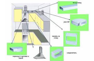
A simple diagram for installing a kitchen hood
The hood is placed above the stove. It is preferable to take the outlet out to the outside. Otherwise, reverse draft is possible from the natural ventilation of the building. Installation instructions and a list of components can be found in our article on installing a kitchen hood.