How is balancing done?
Depending on the flowmeter model, after installation and pressure testing of the heating system, they are set to the initial “open” position. For devices that do not have a built-in valve with speed graduation, an additional valve is set to the “fully open” position, and the system is balanced after startup.
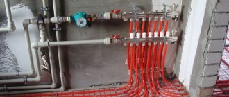
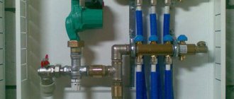
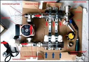
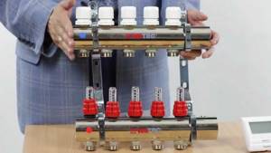
Standard assembly of the manifold group
In combined models, it is possible to preset the number of full valve revolutions. Each revolution reduces the clearance by a fixed amount.
First, the volume of coolant required for each circuit is calculated and its share is determined as a percentage relative to the total volume of coolant for the entire system. In accordance with these indicators, the initial position of the flowmeter valve head on each circuit is set.
The final adjustment is made during operation. At the same time, they are based on real temperature indicators and feelings of comfort.
How does the water meter of a heating floor collector work?
Let's describe how the flow meter works. The functionality of the device is ensured by its valve part; it is equipped with control rings or a valve. When these controls are moved, the lumen of the pipe narrows, accordingly, the flow weakens/increases, the temperature on the circuit changes, and at the same time the float inside the transparent flask moves, showing the set value. In this way, the thermal power of coils with different hydrodynamic resistance is balanced. There are models with a valve installed separately; the operating principle is similar, the elements are simply separated.
So, in a float rotameter, namely such devices are used for floor water heating systems, there is a plastic transparent flask with a float indicator indicating the intensity of circulation. The liquid constantly flows inside, drowns the specified element (it can be called “eternally floating”), which the spring tries to return to its place; the more powerful the flow, the more it sinks.
Step-by-step instructions for installation and adjustment
The rotameter is installed strictly vertically. To ensure that the liquid level in the flask is accurate, the collector itself is also mounted according to the level. If the comb pipe is installed crookedly, the temperature adjustment will be incorrect.
Since finishing work often occurs after installation of the collector, it is necessary to protect the assembly and its components from possible damage. The best option is to make a niche or a special cabinet for it in the wall.
Installation and adjustment:
- Using a wrench, screw the flow meter into the process inlet of the return line of the manifold;
- Turn the membrane (flask) counterclockwise to open the pressure meter;
- Remove the factory protective ring;
- Turn the brass housing ring clockwise to the desired pressure level. This is balancing the energy flow rate. The float on the scale will indicate the set value;
- Cover the brass ring with a cover plate. This must be done to avoid damage to the device, especially if the water heated floor unit is not closed in a niche or cabinet;
- Check the system operation.
During operation of the unit, the flask remains open so that the level of the water float is visible. If balancing is needed during operation, the membrane is simply turned in the desired direction.
How to choose a quality flow meter
The passport indicates the main characteristics of the flow meter, so when choosing a device you need to pay attention to the following characteristics:
- Float rotameters are the cheapest; among them you need to choose devices with a brass body.
- Inner spring material. If it is not indicated, it means that the manufacturer installed an unreliable plastic container.
- The passport must indicate that the spring is made of stainless steel.
- Flask material. As a rule, in all float rotameters the flask is made of polycarbonate. But there are also exceptions. The flask should have a clear and understandable scale.
- Maximum pressure. The flowmeter must withstand 10 bar.
- Maximum temperature. For underfloor heating systems, the upper operating temperature limit should be at least 90 degrees. It is better if it is above 100.
- Bandwidth. You need to select a device in accordance with the power of the circuit. The bulk of flow meters are designed for flows from 2 to 4 cubic meters per hour.
- Quality equipment is always guaranteed for at least 5 years.
Installation and adjustment
According to the manufacturers' instructions, the rotameter is connected to the return collector, but there is an option to install the device on the supply.
The main requirement for installing the device is its vertical location. This installation allows you to determine the exact value of the liquid level in the flask. Therefore, the comb must be placed strictly horizontally in level.
The rotameter is connected by screwing into the corresponding socket on the manifold. The device comes with an O-ring and a union nut. There is no need to additionally seal the device with sealant or other materials.
The workflow of the connected circuit manifold - manifold and flow meter must be fully automated. Therefore, a temperature sensor is additionally connected to the system. With this scheme, when the specified temperature regime of the coolant is reached, the system blocks its full or partial access to the circuits.
Installation of heated floor flow meters
The entire installation process and adjustment of the rotameter for heated floors is performed in the following sequence:
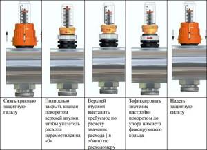
- The flow meter must be screwed into a specially designed technological hole on the manifold. The device is installed using a key in a strictly vertical position.
- Turn counterclockwise and remove the transparent bulb located at the top of the flowmeter housing. After this, you need to remove the ring that is installed for protection by the manufacturer. Then put the cap with the markings back on.
- Turn the body clockwise to the required pressure level. This action is a balancing of the coolant flow rate. In this case, the specified value should be displayed on the scale.
After such actions, it is necessary to check the operating process of the entire underfloor heating system. During operation of the heated floor, do not close the flask on the flow meter. The scale must be constantly visible, since sometimes there is a need for balancing during operation of heating equipment.
According to technical rules, identical installation of several contours, including their length, should be carried out. Otherwise, even using a collector with a rotameter will not give a positive result, and the system will not function correctly.
Manual adjustment of TP collectors
The simplest, although time-consuming, setting method is to adjust the temperature of the heated floor using manual valves. The task is somewhat simplified by installing flow meters (rotameters) on the comb.
Flow meters simplify the dosage of the amount of circulating coolant (flow) in one separate circuit of the underfloor heating system. In the case of group temperature control throughout the collector, the rotameter can also be used to balance the flow of coolant (smoothing out the difference in hydraulic resistance) along loops of different lengths.
The main elements of a flow meter valve are:
- housing with shut-off and control valve. It is screwed into the corresponding technical hole of the manifold;
- a flask made of transparent plastic or glass with a printed scale;
- float indicator that allows you to visually control the flow of liquid through the rotameter.
Manual adjustment of the underfloor heating manifold is carried out by screwing/unscrewing manual valves or adjusting the throughput of flow meters.
The sequence of manually setting the temperature of a warm water floor
At the beginning of the adjustment operations, it is necessary to make sure that the pipelines of the TP system (secondary circuit) are completely filled with coolant and have no air pockets. They are filled following the main heating system (primary circuit). At this time, all shut-off and control valves on the collectors must be closed.
After opening the main valves for the supply and return of the distributors for heated floors, the shut-off devices on each of the loops are opened sequentially. Air is bled through Mayevsky valves or automatic comb air vents. It is recommended to fill the next branch only after the previous one has been completely filled and its air has been guaranteed.
Having completed filling the first loop, it is necessary to turn on the heat pump of the secondary heating circuit and circulate the coolant through its system. The efficiency of liquid circulation is checked with built-in or overhead thermometers. As a last resort, you can simply put your hands on the supply and return pipes at the same time - they should be warm, but with a slight difference in heating.
The filled first loop should be cut off from the collectors at both ends using local shut-off and control valves. Then, the above actions are carried out with the next loop.
After sequential filling of all heat pump circuits, their shut-off devices are opened and the heat pump is switched on to operating mode. The temperature of the warm water floor is adjusted through the supply of coolant to each of its branches. It is set by changing the liquid flow rate (with a valve or rotameter), and control is carried out by changing the temperature gradient between the supply and return flow. Ultimately, this difference for different circuits should be the same, within 5-15C. The longer the loop, the more intense the coolant will cool and the greater its consumption required.
To monitor the correct adjustment of a warm water floor, it is rational to use non-contact laser or contact electric thermometers. Their installation to measure the temperature of the supply and return pipes will help reduce the time to obtain the result of changing settings from several hours to 10-15 minutes.
Adjustment based on return water temperature
Coolant flow, power and temperature difference between the supply and return pipelines are interconnected. If you reduce the coolant flow in the loop, the temperature difference will inevitably increase. It is by this dependence that the correct setting can be determined.
In the event that all underfloor heating loops have the same temperature difference between the supply and return pipelines, this will mean that in all loops the coolant flow corresponds to the current power. And since the temperature in the supply manifold is the same for all loops, it is possible to equalize the temperatures only in front of the return manifold.
It is more convenient to take temperature readings using special thermometers that are mounted between the pipe and the return manifold.
The reference temperature is measured on the longest loop. After this, all other valves are adjusted depending on deviations from this temperature. If the temperature on some loop is lower than the reference one, then the flow rate in this loop is also low. Therefore, the valve of this loop must be opened slightly. If the coolant flow is higher than the reference value, the valve must be closed. After adjustment, you must wait half an hour and then repeat the operation. And repeat this until the coolant temperature in all loops in front of the return manifold is equal.
Working with Manifold Flow Meters
Hydraulic balancing of underfloor heating loops involves normalizing the flow in each coil. Depending on the length, different amounts of incoming coolant may be required so that when passing through the loop it cools exactly to the calculated value. The required flow is quantitatively determined as the ratio of the thermal load on the loop to the product of the heat capacity of water or other coolant and the temperature difference in the supply and return: G = Q / s * (t1 - t2).
You can often find recommendations to determine the coolant flow according to the performance of the circulation pump, that is, to divide its supply in proportion to the ratio of the lengths of the loops. Such advice should be avoided: in addition to the fact that it is quite difficult to calculate the length of each coil, one of the most important rules is violated - choosing equipment parameters based on the needs of the system, and not vice versa. Attempts to distribute flow in the described manner almost always lead to the fact that the flow in the loops differs significantly from the calculated values, which makes further adjustment of the system impossible.
Adjusting the flow with flow meters is quite simple. In some models, the throughput is changed by turning the body, in others - by rotating the rod with a special key. The scale on the flow meter body indicates the flow rate in liters per minute; you just need to set the float to the appropriate position. Almost always, when the capacity of one flow meter changes, the flow rate in the remaining loops changes, so the adjustment is carried out several times, sequentially calibrating each outlet. If such changes are particularly pronounced, this indicates a lack of capacity of the control valves through which the collector is connected, or that the performance of the circulation pump is too low.
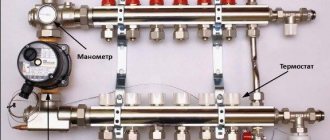
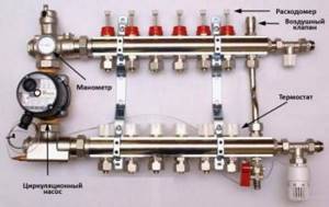
Ideal design of the collector group
The best system is considered to be this collector group, in which the supply manifold is equipped with a rotameter, and a thermostat is installed on the return manifold. Such a system will make it possible to direct a sufficient amount of coolant to each circuit, and the return collector of such a system will close and open the circuits as the water cools.
It is also necessary to say that the system can be improved with an automated Mayevsky tap, which is placed on the supply manifold; for its part, it must be connected to a circular pump with a bypass valve.
It will work like this:
- Mayevsky taps will remove air from the system, which interferes with its good operation;
- If it gets warmer outside, the external water thermostats will close the circuits, and the bypass valve will reduce the increased pressure from inside the system.
If we talk about how a heated floor
, you need to make a correction: there are three types of rotameters:
- The measuring rotameter is installed simultaneously with the valve, which is changed manually, depending on the measured readings;
- The calibrating rotameter controls the amount of incoming coolant;
- The 3rd type combines the previous two, but it also has a very high cost.
Results
It is important to ensure that when the water floor heating system is operating, the flow rate on the collector is visible. This is necessary for maintenance. Each water circuit must have its own flow meter.
We recommend: How to connect a heated floor from a stove?
As you can see, in the equipment, each element performs its own functions, so each one needs to be given sufficient attention, and in order for the entire system to work as one whole, it is worth equipping it with a flow meter and a collector, which will evenly distribute all the heat.
- Related Posts
- How to lay heated flooring under laminate on a concrete floor?
- How does the underfloor heating calculator work?
- How much does underfloor heating cost?
- How to lay polystyrene foam for heated floors?
- How to install damper tape for heated floors?
- How to install a heated floor under a cork?
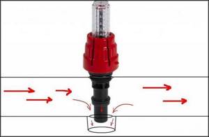
Flowmeter functionality
A rotameter or, to give a full definition to this unit, a float rotameter, at first glance, is a common mechanical device. The design of the product is based on a plastic case (there are models made of brass), inside of which there is a polypropylene float. The body is equipped with a transparent bulb on which a marking scale is applied. The movement of the float up and down inside the device indicates a certain value on the scale, by which one can judge the volume of coolant circulating in the pipeline system - whether it is enough for the full operation of the heating circuits.
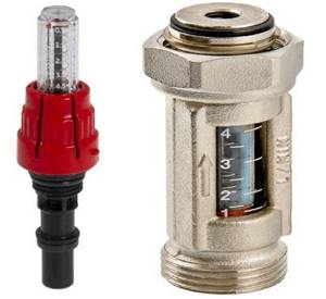
Traditional flow meter for underfloor heating manifold in various versions: on the left - in a plastic case, on the right - in brass.
From a theoretical point of view, the heating system can operate without this device. In this case, you will have to manually adjust the volume of water entering the circuit, based on your personal feelings when the air temperature in the room changes.
- individual circuits of the water floor will be supplied with coolant without taking into account the characteristics of the room, as a result of which the temperature values of the floor surface of heated rooms will differ;
- the energy consumption used to operate heating devices (electricity or gas) will be increased.
For example, you plan to heat the bathroom and children's room at the same time. An autonomous gas boiler will heat water for the bathroom and nursery in the same way, at the same temperature. However, the bathroom is smaller in area and will require less boiler water to heat it than to supply a heated floor in a nursery. You can achieve optimal supply of coolant to heated floors in each room using a flow meter. Consequently, due to the operation of this device, it will be possible to achieve individual temperature values for comfort in the bathroom and children's room.
Assessing the operation and principle of operation of the device, the following conclusions can be drawn:
- the device operates completely autonomously, without requiring additional power sources;
- the operating principle of the flow meter allows you to create optimal coolant flow for heating circuits, significantly reducing the energy consumption of heating devices;
- the design of the device provides visual control over the amount of water in the pipelines;
- the collector together with flow meters for underfloor heating significantly facilitates control over the operation of the entire system, is easy to install and unpretentious to maintain.
Setting up heated floors manually
In the case when the floor heating circuit operates without additional equipment and automation, the warm floor adjustment is carried out manually. The homeowner independently sets and controls the heating of the room to a comfortable level.
System preparation and commissioning
You can manually adjust heated floors thanks to a thermal head - a regular tap installed for water supply and return flow. In this case, the system will not be overloaded with additional devices and automation. For the owner, this is beneficial because it saves money on installing the circuit, but it creates difficulties in the operation of the crane.
It will be more convenient to use a flow meter (also known as a rotameter) installed at the inlets of the circuit near the collector. In this case, the adjustment comes down to monitoring the difference in readings of these devices - 0.3...0.5 liters. Manual adjustment assumes the correct first start-up of the floor heating system, during which all possible failures and malfunctions are identified.
The system startup process and its heating
It is necessary to put the underfloor heating system into operation not only after its installation, but also every year before the onset of cold weather. This process consists of several stages:
- Descent through air pipes;
- Filling the circuit with water;
- Adjusting heated floors and setting their operating mode for maximum performance.
Typically, owners install controllers, sensors and programmers on the circuit, the operation of which simplifies interaction with the system, but does not exclude the participation of the owner. The first launch is always done manually!
Setting up a heated floor step by step:
- Checking the valves on the manifold-distributor. All of them must be in the “closed” position;
- Check the filling of the heating system with water (coolants);
- Turn on the pump at minimum speed to heat the system;
- Open the return and water supply valves (“Open”);
- Check that the circuit is filled with coolant and air is discharged through the pipes through the vent (located in the manifold);
- Make sure that the circuit is filled with water and the air in the pipes is removed using a vent on the manifold;
The circuit fills gradually and slowly; the fewer revolutions the pump makes, the less likely it is that air pockets will occur in the pipes!
- Turn on the condensing heating boiler;
- Make sure that coolant is supplied to the circuit;
- Check the return;
- Perform a circuit performance test;
- Close the water supply and return valves;
- Carry out the procedure with each existing circuit.
Having filled all available circuits, the valves on the manifold are placed in the open position. The system does not immediately heat up to the set temperature, since it is quite inert to heat. The effect will be noticeable in 10 hours, maximum in a day. The duration of the response is related to the multi-layer arrangement of the floor heating system and the length of the circuit.
Good flow meter
In the store you can find a large selection of different rotameters, so in order to choose a good copy, you can look for it according to the properties listed below:
The flowmeter must have a good body without chips or protrusions
The body material is brass, but the top is covered with nickel. The internal spring of the rotameter must be made of stainless steel. Polycarbonate material is an example of a wonderful material for a translucent flowmeter bulb, because this material will withstand high temperatures, as well as some physical influences. It is impossible to determine this in a store, so you will need to trust the manufacturer and pay your own attention to the indicators: the device must maintain a temperature of up to 110°C, and also a pressure of 10 bar. The largest throughput of the rotameter should not be less than 2-4 cubic meters per hour. The measuring scale must correspond to these indications. The warranty for such products is long, often from 5 years.
Conclusion
A manifold for a heated hydraulic floor with flow meters makes it possible to control the flow of the coolant, which ensures the optimal floor temperature in each room connected to this circuit. This option for installing a heated floor system additionally saves money, because you spend less energy on water heating.
Heated floor from a 2-circuit boiler.
Hello. Has anyone encountered diagonal connection of collectors? The thing is that I am installing heating (radiant wiring) and heated floors. There are two collectors, one with flow meters for floors and the other without for radiators. For floors, it’s clear that the entire flow rate is adjustable, but for radiators it is not. The question is, if the radiator manifold is connected to the supply pipes diagonally and not one-sidedly, as usual, will the radiators heat up evenly? in fact, this is the same two-pipe of the same direction and not of the dead-end type. I mean maybe this way the pressure will be distributed more or less evenly across the radiators
Is this something like a diagonal radiator connection? If you look at everything as a whole, I think your idea will work, but you need to calculate it. Isn't it easier to balance?
It’s impossible to balance because Ball butterfly valves are located on radiators.
I don't rule out your idea. If you can’t balance it, then screw the flow meters into the supply manifold or try an experiment using your method.
r072, you're digging in the wrong place. If the diagonal connection is not justified by convenience, do not bother.
I didn't notice this game. And yes, this is game.
You’ll notice game while hunting, but I had a pointed question about hydraulics. I’m not interested in convenience, but they installed a manifold without flow meters for 12 outputs. they said it should be so. 12 branches are all different in length, as are the radiators in sectionality. Each circuit has its own resistance, as a result of which my radiators heat differently and I’m tired of balancing them with taps. So I’m asking about the diagonal connection of collectors and not the one-way method as usual. for example, many turn on a radiator of 12 sections using the side one-sided method, then 3-4 fins do not heat up, they begin to screw the tube into the bottom of the radiator up to section 8 so that the liquid cannot flow into the return from the top supply through the nearby sections, as a result of which the pressure is transferred to the distant sections although it could just connect it diagonally and that's all. But apparently not everyone likes this arrangement of taps. So in my case, although I’m not good at this, I’m just wondering if you have specialists, maybe someone has already done this or knows whether this option will work or not, I need an exact answer and if not, why not. in fact, this is the same two-pipe system of a passing direction. if you draw this two-tube on a sheet of paper and assemble it into an accordion, the same collector turns out to be only long branches; the person who answered earlier more or less understood the essence
Typical connection diagrams
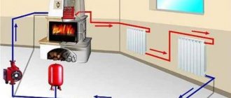
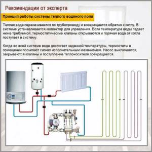
Water heated floors are rarely used as the only source of heating. Heating only due to underfloor heating is permissible only in regions with a mild climate, or in rooms with a large area, where heat removal is not limited by furniture, interior items or the low thermal conductivity of the floor covering. Almost always it is necessary to combine radiator circuits, hot water preparation devices and underfloor heating loops in one heating system.
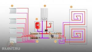
Typical diagram of a combined heating system with connection of radiators and underfloor heating circuits. This is the most technologically advanced and easily customizable option, but it also requires significant initial investment. 1 - heating boiler; 2 — safety group, circulation pump, expansion tank; 3 - manifold for separate two-pipe connection of radiators in a star configuration; 4 — heating radiators; 5 - underfloor heating manifold, includes: bypass, three-way valve, thermostatic head, circulation pump, combs for connecting underfloor heating circuits with gearboxes and flow meters; 6 - heated floor contours
There are quite a large number of variations in the design of the boiler room piping, and each individual case has its own principles of operation of the hydraulic system. However, if you do not take into account very specific options, then there are only five ways to coordinate the operation of heating devices of various types:
- Parallel connection of the underfloor heating collector to the main line of the heating unit. The insertion point into the main line must be made up to the connection point of the radiator network; the coolant supply is provided by an additional circulation pump.
- Association according to the type of primary and secondary rings. The line, wrapped in a ring, has several supply connections in the supply part; the coolant flow in the connected circuits decreases with distance from the heating source. Flow balancing is performed by selecting the pump supply and limiting the flow with regulators.
- Connection to the extreme point of a coplanar manifold. The movement of the coolant in the heated floor loops is ensured by a common pump located in the generator part, while the system is balanced according to the principle of priority flow.
- Connection through a hydraulic separator is optimal when there are a large number of heating devices, a significant difference in flow rates in the circuits and a significant length of underfloor heating loops. This option also uses a coplanar manifold, but the hydraulic arrow is necessary to eliminate the pressure drop that interferes with the correct operation of the circulation pumps.
- Local parallel loop connection via unibox. This option is well suited for connecting a short-length heated floor loop, for example, if you need to heat the floor only in the bathroom.
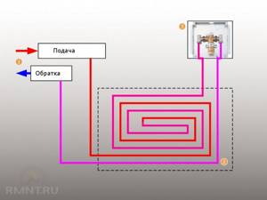
The simplest option is to connect a heated floor circuit to a radiator heating system with a coolant temperature of 70-80 °C. 1 - line with supply and return of the high-temperature circuit; 2 - heated floor contour; 3 - unibox.
It must be remembered that the nature of the operation of a heated floor may also change depending on the installation pattern of the coil. The “snail” scheme is considered optimal, in which the tubes are laid in pairs, which means that the entire area is heated almost evenly. If the warm floor is arranged as a “snake” or “labyrinth”, then the formation of colder and warmer zones is practically guaranteed. This drawback can be eliminated, including through proper configuration.
Appearance of a problem
First of all, you need to analyze a specific example of the occurrence of such a problem and its consequences:
- You install heated floor
in the bathroom, guest room and kitchen; - They are connected to one collector;
- The area of the bath, kitchen and living room is clearly different, due to this the length of the heated floor
will vary in any room, and naturally the consumption of the coolant (water) will be completely different.
It is necessary to say what this will lead to. Short heating rings have less hydraulic resistance, due to which the water in them moves much faster than in long circuits, which creates a temperature difference in the rooms at the same temperature of the coolant supplied from the collector.
An example of a solution to a problem, in which we will analyze the principle of correction, will be a primitive wall-mounted radiator. If you connect radiators with different numbers of sections and pipe lengths to one collector, the problem described above will appear (read: “Heated floor collector diagram - how everything should work”).
The problem with radiators is easily solved, because the instructions say that by installing a thermostat on each battery, you will be able to control the quantitative flow. In most cases, the thermostat is a traditional valve. A similar problem is solved with a heated floor system.
Balancing the heating circuit
- Calculate the total amount of coolant in liters that passes through the manifold with flow meters for heated floors in 1 minute. Take the result obtained as 100%.
- Next, determine the percentage flow rate of each heating ring and convert them to liters/min.
- Next, use the valve on the rotameter to adjust the supplied amount of coolant.
- With these steps you will perform a tentative balancing of the heating circuit, so in order to set the actual values, monitor the rotameter readings, based on which you can calculate the flow rates of the circuits connected to the collector.
In the store you may encounter a wide selection of different rotameters, so in order to choose a high-quality copy, you can select it according to the following characteristics:
A manifold for a warm water floor with flow meters allows you to control the flow of coolant, which ensures a comfortable floor temperature in any room connected to this circuit. This method of organizing a heated floor system additionally saves money, because you spend less energy on heating water.
To regulate the temperature, flow meters are provided in the manifold. These devices control the flow of coolant, in this case water.
Theoretically, it is quite possible to do without installing a flow meter in the manifold. However, if you do not install this device, then:
A simple example can be given: a bathroom and a bedroom. A gas or electric boiler heats water equally for both the bath and the bedroom. But the bathroom is at least 3 times smaller in area than the bedroom. Accordingly, the bathroom will be hot and the bedroom will be cool with the same water supply to the floor heating system. This situation is due to the fact that in the bedroom the total length of plastic pipes in the area is much greater. It is precisely in order to regulate a comfortable temperature in the entire apartment that it is desirable to install such a device.
Principle of operation
The flow meter itself consists of several parts:
The flask is usually made of durable glass; the body can be plastic or brass. The float is located inside the flask; it serves as an indicator of the coolant speed. The flow meter is also called a float rotameter.
Solving the problem with underfloor heating contours
By connecting underfloor heating circuits to one manifold group, you can balance them in two ways:
- The first method involves creating even rings, but you can put several of them in one room, for example, you can put one heating ring in the bathroom, three in the guest room, and two in the kitchen. Likewise, the heating of all rings will be the same.
- If you do not want to create several rings in one residential area, then there is also a solution for you. Heating circuits can be of different lengths, but they should be connected through a specialized device - a flow meter
for heated floors.
A flow meter
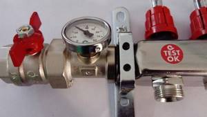
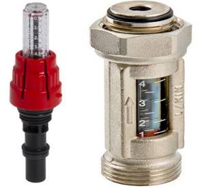
or rotameter is a combination of balancing valves that limit the amount of coolant released into the system. You can see an example of a rotameter in the photo.
Adjusting the coolant supply
If the warm floor in the apartment has several circuits that differ in length or temperature conditions, installing a heating distribution manifold with flow meters (rotameters) will help out. The fact is that the coolant follows the path of least hydraulic resistance, that is, first of all, it will be directed into short-length pipelines.
In order for large loops to heat up with the same intensity, it is necessary to adjust the fluid supply, reducing it for short pipelines and increasing it for longer ones. Therefore, the water heated floor comb is equipped with a balancing rotameter for each loop.
The flow meter scale determines the intensity of coolant flow in a particular circuit. And in accordance with these indicators, the throughput of the flow valve is adjusted.
The purchase and use of adjustable rotameters is justified only in the case of manual adjustment of the amount of coolant for circulation through the branches. If each circuit is regulated by its own servo drive under the control of an electronic thermostat, then the use of such fittings is not required.
At the same time, in the collector block operating in automatic mode, for additional visualization, rotameters without a control function can be mounted. However, such devices are no longer installed on top of the comb body, but are embedded between its outlet for connecting the loop and the outlet of the heated floor pipeline.
Equipment and capabilities
Products are manufactured under the Valtec brand by an Italian company. They have been on the Russian market since 2003, so they know our realities first-hand. We produce a wide range of plumbing engineering fixtures and devices. And collectors for heated floors are among them.
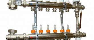
general description
The Valtec underfloor heating manifold is made of brass or stainless steel. Or rather, most often, the body is made of stainless steel, and the “filling” is made of brass. In the catalog they are called a manifold block, since there are a couple of devices - for the supply and for the return pipeline. Complete kits are equipped with:
- there are flow meters on the feed comb;
- on the return pipeline there are manual shut-off valves.
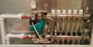
Below is the supply and there are flow meters.
At the top there is a return pipeline, manual valves are installed. In this option, using flow meters, you can adjust the coolant flow in each of the loops, and manual valves on the return pipeline serve to block circulation. But this configuration can be automated. To do this, servo drives are installed on manual valves, which are connected to thermostats installed in the premises. In this way, a constant floor or air temperature can be maintained. Depends on where the heat sensors are installed, because the thermostat reacts to their readings.
An automatic air bleeder is also installed on the Valtec manifold. This is a device that allows you to remove air trapped in the coolant automatically.
Range
All collector blocks for Valtek underfloor heating can be divided into two groups: with and without adjusting flow meters. There are only three options in the first group and two in the second, but in each the number of connected taps is from two to twelve.
With flow meters on supply
- VTc.594.EMNX. Body - stainless steel AISI 304, fittings - brass CW617N, seals - EPDM 70Sh, number of outlets - from 2 to 12. Operating pressure 8 bar, nominal diameter of manifolds - 1 inch, outlets - 3/4″ external thread, connection - eurocone. Price - from 9 thousand rubles. (for 2 outputs), up to 25 thousand (for 12 outputs).
- VTc.589.EMNX. Manifold for propylene glycol systems. Body - AISI 304 stainless steel, brass fittings and EPDM 70Sh rubber seals. Working pressure 9 Bar, coolant temperature not higher than 90°C. The nominal diameter of the collectors is one inch, the outlets are 3/4 inch with a Eurocone.
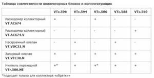
Compatibility table for various Valtec manifolds with components
VTc.596.EMNX. Valtec brass manifold (CW617N brass) with nickel plated. EPDM 70Sh seals, fittings made of the same brass. Working pressure 10 Bar, outlet connection - Eurocone, diameter 3/4″.
nominal collector diameter 1 inch, number of outlets from 3 to 12. Price from 12 thousand rubles. for 3 exits, up to 38 thousand rubles. for 12 exits; nominal collector diameter 1 and 1/4 inches, number of outlets from 4 to 12. Price from 9 thousand rubles. for 4 exits, up to 45 thousand rubles. for 12 exits. With manual valves
VTc.588.EMNX. Stainless steel underfloor heating manifold VTc.588.EMNX with thermostatic valves. Coolant - water or propylene glycol, operating pressure 9 Bar, temperature 90°C. There are manual adjustment valves on the supply side. The number of outputs is from 3 (6 thousand rubles) to 10 (15 thousand rubles), connection via a 3/4″ eurocone, nominal collector cross-section is 1″. VTc.594.EMNX. Valtec brass manifold for systems with elevated temperatures - up to 120°C, pressure 10 Bar. Includes manual balancing valves and thermostatic ones.
nominal diameter of the collectors is 1″, the number of outlets is from 3 (10 thousand rubles) to 12 (27 thousand rubles); collectors with a cross section of 1 and 1/4″, the number of outlets from 4 (16 thousand rubles) to 12 (36 thousand rubles).
The basic package includes manifold plugs, automatic air vents, drain valves (for filling or draining coolant), and brackets for installation.