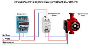
The connection diagram for the circulation pump to the electrical network is as follows:
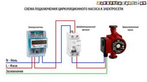
Please note that the pump connection diagram must include either a differential circuit breaker (as in our diagram) or a combination of a protective circuit breaker and an RCD (Residual Current Device). This is required, first of all, to protect a person from electric shock in the event of a pump malfunction or incorrect connection.
Detailed photo instructions for connecting the circulation pump to the electrical network, according to this diagram - HERE (link will open in a new window).
Most circulation pumps in heating systems are connected according to this standard scheme. The main disadvantage of which is that the pumps have to be turned on and off manually each time, so they are often turned on at the beginning of the heating season and turned off at the end. The disadvantages of this connection method, I think, are obvious: excess energy consumption and a decrease in the service life of the pump.
You can automate the operation of the circulation pump in the heating system in order to reduce energy costs and increase the overall service life of the pump by connecting it through a thermostat.
What to choose from
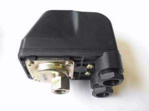
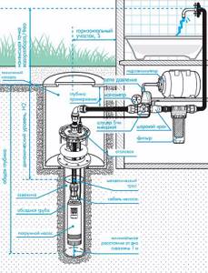
The operating principle of the simplest scheme, which includes automation for the pump and a hydraulic accumulator, boils down to the fact that the pump raises a certain column of water. This creates some pressure in the pipeline. First of all, the water enters the tank, which compensates for water hammer, after which it approaches the pressure switch or automation. It already has a primitive mechanical sensor that, in response to a specific pressure, turns on or off power. But not all types of automation for deep-well pumps work on this principle, in addition, some of them do not require a hydraulic accumulator. There are currently three generations of pressure switches available.
Each of them has its own characteristics that should be taken into account when choosing and installing. It is impossible to buy automation separately from the well pump. Before choosing automation, you need to know in what modes the pump can operate and what protection systems are integrated directly into it. Modern units may have built-in sensors that monitor excess pressure or exceeding the permissible temperature of the unit. Pumps are also available that have dry-running protection. It involves stopping the equipment if the well runs out of water. Pump automation can also be equipped with the same systems. There is no point in duplicating capabilities. In this situation, first-generation automation will be sufficient.
The simplest option
Automation for the pump, which belongs to the first generation, is a simple electromechanical device. Among the main types are:
- float;
- dry running sensor;
- pressure switch.
The first is mostly used in cases where we are talking about pumping out liquid from places of flooding or when pumping it from one container to another. The float is connected directly to the pump and reacts to changes in water level. As soon as it drops to a critical level, he turns off the pump. This is realized by a changeover mechanism, which is located in a sealed housing and through which power is supplied to the pump. The dry running sensor can be used independently or as part of an automation system for a deep-well pump. The essence of the element’s functioning is to monitor the presence of water in the system. If it disappears, the dry-running module turns off the pump so that the seals and the motor do not fail.
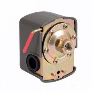
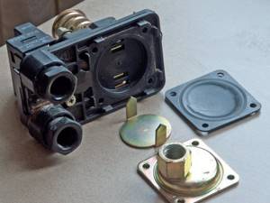
The pressure switch is a small unit. It can be mounted next to the pump or on the battery tank. It all depends on what is more convenient. The simplest device consists of two main modules:
- electrical;
- mechanical.
The electrical part is represented by two groups of terminals. The wires from the power cable are fed into one of them, and the wires that go to the pump into the other. There is a special switch that is activated by a mechanical part. It is represented by two springs and additional elements. Through a special hole, water is pressed onto the membrane, which comes from the pump. By acting on it, the force is transferred to the spring. The spring operates the switch, which closes or opens the contacts.
Note! Using a simple relay option requires the presence of a hydraulic accumulator.
Second generation
The next generation of automation is a device that is somewhat more complex in structure and in principle of operation. Instead of a simple mechanical circuit, such relays use additional sensors. They are mounted on the pump part, as well as at certain points in the pipeline. This approach made it possible to exclude the hydraulic accumulator from the system. Pressure is measured directly in the pipeline. As soon as the tap is turned off or any device begins to use water, the sensor records the pressure drop. The sensor transmits a corresponding signal to the main control unit, which turns on the power supply to the pump. As soon as the pressure reaches the required level, the reverse process occurs.
These are not the only sensors and capabilities of this type of device. Some models have an additional temperature sensor. It is able to monitor the condition of the pump and turn it off when a critical level is reached. If this is not done in time, then the windings will fail and expensive repairs will be required. Emergency shutdown function available. It is necessary in cases where a pipeline breaks. By blocking the leak, the pump automation prevents flooding of the house or property. Some modules have a dry-running protection function. The water level sensor will tell you when the water level drops and the pump needs to be shifted.
Advice! It is worth carefully weighing the need for additional functions. They significantly affect the price, but a conventional automation unit can cope with such tasks.
Automated system
It is already classified as the third generation of such devices. It is a whole mechanism. It will cost much more than the previous two options, but on an industrial scale you cannot do without this type of device. Such automation also performs the functions of turning pumping equipment on and off depending on changing circumstances, but does this in an intelligent mode. This makes it possible to extend the life of the pump. In addition to the main indicators, this type of automation monitors the power that the pump consumes during operation. The more liquid is required and the higher the height it must be raised, the greater the consumption of the device.
Conventional automation always supplies the full available power to the pump. But in some cases it harms the equipment. In order to save electricity, as well as engine life, it would be more advisable to supply only as much power as required for specific tasks. It is almost impossible to make adjustments before each turn on. This is precisely why the third generation automation was created. The microcontroller constantly monitors the pressure, pressure and amount of water supplied to the surface. If the flow rate immediately increases, the sensor gives a signal and the automation increases the pump power.
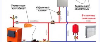
The connection diagram for the circulation pump through the thermostat is as follows
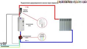
The heating system itself in the diagram is primitive, presented for a general understanding of the operation of the thermostat, but it can be seen from it that a pipe thermostat is installed on the heating pipe near the boiler, which measures the temperature of the pipe, and depending on it, turns on or off the circulation pump.
Also, if you do not find a special pipe thermostat (as in the diagram), you can use a regular room thermostat with a remote temperature sensor, which is attached to the pipe.
Other schemes for connecting a circulation pump through a thermostat, for example, to regulate the room temperature, most often cannot be used. And although it seems logical to turn off the circulation of hot water (or other coolant) when the room becomes too hot and turn it on when it’s cold, this approach is wrong. In this case, the thermostat should control the boiler, turning it on and off if necessary, and not the pumps that drive the coolant through the system.
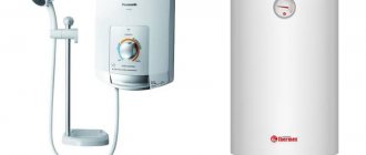
Scheme for connecting the circulation pump via an uninterruptible power supply (UPS)
For non-volatile heating systems, the heart of which are gas or solid fuel boilers that consume little electricity, this solution lies in the implementation of a circuit for connecting circulation pumps through uninterruptible power supplies.
At the same time, the autonomy of the system increases many times over. Familiar to many power outages in the private sector, which, as luck would have it, happen on the coldest, darkest nights and lead to freezing and often destruction of both the heating system and the entire house, are now practically not scary for you.
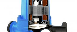
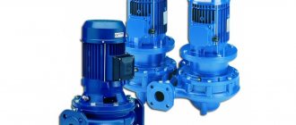
Purpose and design of a surface pump
The surface pump does not require immersion; only the water intake hose is lowered into the water. The maximum depth it can handle is nine meters. Therefore, it is not suitable for a well, but for a shallow well or spring it is just right. In addition, such a pump copes well with pumping water from basements and watering a personal plot. Surface pumps are also great for wells on quicksand.
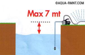
The maximum depth from which a surface pump can lift water is about seven meters. In this case, it is necessary to observe the “vertical-horizontal” ratio: for one meter of vertical there are four meters of horizontal
Surface pumps can be of three types:
- vortex;
- centrifugal;
- pumps with external ejector.
The first ones are the most affordable and compact. They create pressure 3-7 times higher than similar centrifugal ones, but have low efficiency - only forty-five percent. They cannot be used for pumping water containing large amounts of sand or other impurities, as this will lead to rapid wear of the impellers. Such a pump lifts water through a rotating shaft and a wheel on which “blades” are located. The latter transfer energy to the water from the working axis.
The latter are also not suitable for supplying heavily contaminated water, but they do an excellent job of removing air bubbles and plugs in the system. They are more expensive than vortex ones because they have more stages. This design works thanks to wheels that build up pressure. They are driven by a working shaft supported by bearing systems.
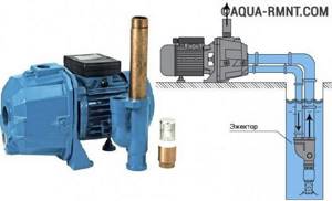
Installing an ejector significantly increases the maximum suction depth of a surface pump, but reduces its efficiency
Pumps with an external ejector are now practically not used. They have been replaced by submersible pumps, whose productivity is much higher.
There is a wide range of submersible pumps on the market. There are reviews of some of them on our website. For example, the “Rucheek” unit: https://aqua-rmnt.com/vodosnab/nasos/nasosy-otzyvy/nasos-rucheek.html.
What is important to know?
The wiring diagram and methods of connecting a device such as a circulation pump to electricity can have different designs. The choice of a specific option is determined by the characteristics of the heated object, as well as the location where the device is located. There are two ways to connect it:
- direct connection to a 220 V power supply;
- connection to an uninterruptible power supply, which in turn is connected to a 220 V or 220/380 V network (in the case of a three-phase UPS).
By choosing the first method, the consumer risks being left without heating in the event of a prolonged power outage. This option can be considered justified only if there is a high degree of reliability of power supply, reducing the likelihood of a long power outage to a minimum, and also if there is a backup source of electrical energy at the site. The second method is preferable, although it requires additional costs.
Detailed Analysis: Pros and Cons of Surface Pumps
Surface pumps have many advantages:
- Compact overall dimensions;
- Light weight;
- Affordability;
- Easy to install, operate and maintain. Installing a surface pump does not require special knowledge, skills and experience;
- Ability to work with a water layer of less than 80 cm. In such conditions, submersible pumps can no longer operate;
- Cooling by air, and not by water, like submersible ones;
- High water pressure;
- High efficiency;
- No need to supply electricity to the water intake;
- High reliability and durability;
- Stable operation even in the presence of air pockets in the system.
Also, surface pumps (as a class of equipment) have a number of disadvantages:
- Sensitivity to the presence of sand, impurities and other water contaminants;
- The maximum depth from which water can be raised is about nine meters;
- When using an ejector, the reliability and performance of the system are significantly reduced;
- Noise. It is better to allocate a separate room for the operation of the surface pump;
- The need to fill the suction line with water.
Connection methods
Connection to the electrical network using a plug and socket . This method involves installing an electrical outlet in close proximity to the place where the circulation pump is mounted. Sometimes they can be supplied with a connected cable and plug included, as in the photo:
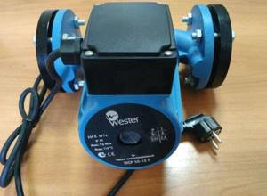
In this case, you can simply plug the device into the mains using an outlet located within reach of the cable. You just need to make sure there is a third, grounding contact in the outlet.
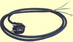
If there is no cord with a plug, they need to be purchased or removed from an unused electrical appliance. You should pay attention to the cross-section of the cord conductors. It should be in the range from 1.5 mm 2 to 2.5 mm 2. The wires must be stranded copper, ensuring resistance to repeated bending. The cord with a plug for connecting electrical appliances to the network is shown in the photo below:
Before connecting the circulation pump, you need to find out which of the three wires of the cord is connected to the ground pin of the plug. This can be done using an ohmmeter, while at the same time checking the integrity of the remaining wires.
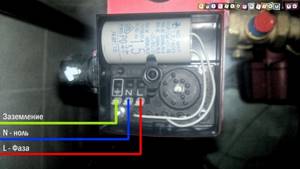
Open the terminal box cover. Inside the box there are three terminals designed to connect the device to the network, marked as in the picture:
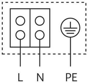
We unscrew the clamp of the cable coupling (in the first photo it is a plastic nut into which the cable is inserted), put it on our cord, and insert the cord into the coupling. If there is a cable tie inside the box, thread the cord through it. We connect the ends of the cord wires, previously stripped of insulation, to the terminals.
The wires connected to the plugs of the plug should be connected to the L and N terminals (don’t be afraid to mix them up, this is not critical), the wire of the grounding contact of the plug should be connected to the PE terminal (but you can’t make a mistake here). The instructions supplied with the product prohibit its operation without protective grounding. Next, tighten the clamp (if any), tighten the cable sleeve clamp tightly, and close the terminal box cover. The pump is ready to be plugged into the mains.
Fixed connection. The connection diagram for the circulation pump to the electrical network with grounding is provided below:
The requirements for the wire cross-section here are the same as in the previous version. The cable for this installation can be used either flexible or inflexible, copper, VVG brand, or aluminum, AVVG. If the cable is inflexible, the installation should ensure that it does not move. To do this, the cable along the entire route is secured with clamps.
Checking the pump operation
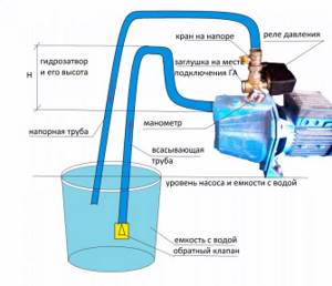
Pump test diagram
In order for the pumping station to operate in automatic mode with normal on/off cycles, it is important to check the tightness of all connections and adjust the operating pressure of the membrane tank. Before starting the equipment, the cavities of the pump and accumulator must be filled with water.
After the station starts operating, it is monitored at what pressure indicators the equipment turns on and off. The optimal low level for switching on is considered to be 1.5-1.8 bar. A good upper level for shutdown is 3-3.5 bar. If the specialist notes a discrepancy between the actual indicators, they need to be adjusted. To do this, open the relay cover and turn the screw marked “DR” (disconnect indicator) towards + or -. These symbols indicate increasing or decreasing atmospheres respectively. The switching pressure is adjusted using the screw marked “P”.
A correctly assembled and connected station operates cyclically and does not exhibit leaks. If the technician did everything correctly, you can backfill the external water supply. It is advisable not to compact the soil. It is gradually added after settling.
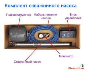
Well pump kit
Let's look at the encountered (recommended) submersible well pump kit. Typically this kit includes:
- The pump itself. It is often sold separately;
- Electrical cable for connection. Included in the pump kit;
- Automation block. Sold as a set or as additional equipment;
- Hydraulic accumulator (expansion tank). Sold as additional equipment.
The given equipment for a well pump is the maximum and is not typical for all manufacturers of well pumps. The automation unit (control system) and hydraulic accumulator may not be included in the kit and their need is determined by the water supply scheme of the house. In the simplest version, the well pump is equipped only with an electrical cable for connection.
Understanding this, let's consider three options for connecting a well pump.
- Connecting a well pump to power supply without automation;
- Connecting the well pump to the power supply with the control unit (system) (automation unit);
- Connecting the well pump to the power supply via a pressure switch.
Length of water pipeline and number of nodes
Although water will move horizontally through the system, losses in nodes and pipes cannot be avoided. It is recommended to purchase purchased equipment with a power reserve of up to 20%.
These devices are also divided into two categories:
- centrifugal , which have a higher price and better performance;
- vibration ones , which cost less and work worse.
Vibration pumps have a suction valve, which can be located:
- at the top of the device;
- at the bottom of the device.
The ability to avoid the ingress of bottom dirt, in the first option, can be compensated by the problem of working with a low water level in the well.
The second option has downsides - such a pump sucks up clay near the bottom, while the low water level will become much less of an obstacle.
The installation of vibration devices is not recommended in sand wells, which are generally considered to be all channels drilled to the depth of interstratal or groundwater.
Connecting a well pump without auxiliary equipment
Without a control unit, automation unit or other auxiliary equipment, the pump's power supply cable is connected to a pre-installed electrical outlet with a grounding contact.
Grounding of a borehole (submersible) pump is mandatory. To directly connect the grounding, the GZSh (main grounding bus) of the house is used, which in turn is connected to the existing grounding loop of the house.
An electrical cable with a grounding conductor is used to supply power to the pump socket. The supply voltage of the submersible pump is 220 volts.
To power the pump, you need to select a separate electrical group and protect this group with a circuit breaker. The rating of the circuit breaker is calculated based on the electrical power of the pump. So for pumps up to 3,000 W you need a 10 Ampere circuit breaker, for pumps of higher power you will need a 16 Ampere circuit breaker.
Possible errors when connecting equipment
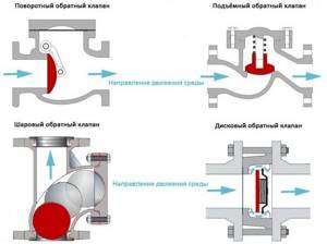
Types of check valves
Pump failure cannot be avoided if the height of its suspension is incorrectly determined. If set too low, small pebbles or sand will get into the pump. If, on the contrary, it is too high, air may be sucked in. Neglecting to install a non-return valve has a negative impact on the pressure device. In such a situation, each time it starts, it first fills a vertical pipe with water, and after shutting down, it is affected by a water hammer.
As the height of the water rises, the impact force increases, so the damage done to the pump will be greater.
It is also not recommended that the cross-section of the water supply pipe be too small. The operating period will remain unchanged, but this will have a bad effect on performance. Uninstalled electrical protection, especially in areas with voltage surges, can cause pump failure.
It is better to connect electrical devices through stabilizers, and complex and expensive electrical equipment through special control and protection stations. The cross-section of the electrical wire must be sufficient, otherwise the operating time of the motor will be significantly reduced.
If automation and instrumentation are installed incorrectly, as well as when pressure equipment is connected to the well, an accident in the system is inevitable. If you know little about the topic, it is better to entrust the work to professionals.
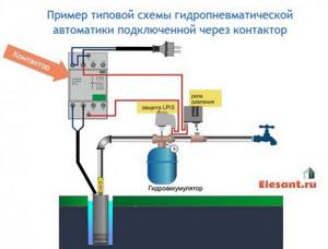
Connecting a well pump to power supply with a control unit (automation unit)
Direct connection of the pump is fraught with rapid failure of the pump. The main cause of the malfunction is the pump running idle when the water level drops.
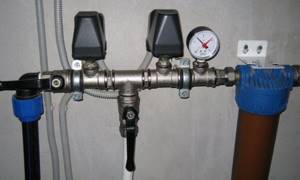
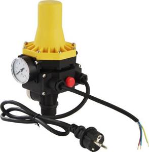
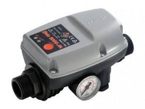
For simple water supply systems, the best option is to include ready-made (factory) automation units in the water supply scheme (example in the photo). Sometimes such units are called deep-well pump control stations. Sometimes with a hydraulic controller. They are needed:
- For smooth start and smooth stop of the pump;
- For automatic pressure maintenance;
- Protection of the pump from “dry pumping”, without water;
- Protection of the pump from power surges;
- Protection against lack of water intake;
- Network overload protection.
Block models are different and the set of listed functions may change. An automatic control unit for a well pump is a necessary device, and that is why reputable companies include it in the pump package, often with limited functionality.
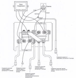
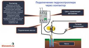
The automation unit (hydraulic controller) is quite compact in appearance. The connection is also simple, and a simple electrical circuit of a well pump with a control unit can be represented as follows.
However, for longer operation of the automation unit, it is better to consider the diagram of its connection through a contactor. The controller will ensure simultaneous activation of the automation unit with the submersible pump.
Features of equipment installation
There are two options for installing the pump:
- The self-priming device is mounted next to the water source. A special submersible hose is lowered into the water at one end and attached to the pump at the other.
- The submersible device is attached to the pipe. If it is a flexible hose, then an addition to the fasteners can be a cable, which is attached with one end to the pump, and the other to any stable element with a well. A flexible installation option is preferable, as it allows you to adjust the immersion depth of the unit. The pump is completely immersed in water. Most of these devices do not tolerate dry operation well. Therefore, it is always worth monitoring the level in the well or purchasing a pump with a float switch that will protect the device in the event of no or critically low water levels.
It is recommended to install a check valve on the pipe itself, which will keep water in the system.
The algorithm for installing submersible equipment includes the following points:
- All pipes are installed. If the pump will be installed on a rigid pipe, then it is recommended to place a small piece of flexible hose between it and the main channel for moving water into the house, which will dampen engine vibrations.
- The following are connected to the device: - cable, - electrical wire, - hose.
- The pump smoothly lowers to the bottom of the well.
- When the unit touches the bottom, the entire structure should be raised to a height of half a meter to a meter from the point of contact.
- The cable must be firmly secured, the wire must be connected to the network, the hose must be connected to the rest of the system and placed in the fastening channels.
- It is recommended to provide the upper hole of the well with a cover to prevent foreign objects and dirt from entering the system.
The electrical connection should only be made to a grounded source using a circuit breaker according to the following diagram:
Electrical connection diagram for a well pump
When installing the pump, you may need metal fluoroplastovie bushings; their options can be viewed here https://cema-bearing.com/metalloforoplastovie_vtulki/.
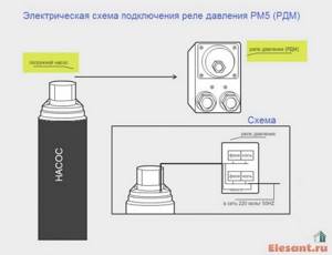
Connecting the well pump to power supply via a pressure switch
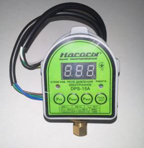
To reduce the cost of the pump kit, you can connect the pump without a control unit, using only a pressure switch.
The pressure switch ensures that the pump is disconnected from the power supply when the water pressure in the system reaches the upper limit and the pump is turned on when the water pressure reaches the lower limit. When working in a water supply circuit with an expansion tank (hydraulic accumulator), pressure thresholds are measured in the tank.
Connection diagram
Basic parameters for choosing a pump
So, we have already written about the height to which the water needs to be raised. What else should you pay attention to when choosing? We need to know exactly the distance of the well from the house, and the volume of pumped liquid, which will depend on the total volume of the water supply network and the maximum possible water consumption at any given time. A trivial example: we open the tap closest to the point of entry into the building - we get good pressure, open the second one - the pressure drops, and at a remote point the water flow will be the smallest.
The calculations here are, in principle, not complicated; you can do them yourself by using an online calculator, or simply by studying the instructions from the manufacturer.
Advice! Household appliances that work with water need to constantly maintain the pressure in the pipeline at a level of at least 0.3 Bar. Consider this point also when choosing a pumping station.
What does the pressure in the system depend on? It depends on the power of the pump and the volume of the hydraulic accumulator - the larger it is, the more stable the average pressure in the water supply. The fact is that when turned on, the pump does not work constantly, since it requires cooling, and when the operating pressure is reached, it should not continue to increase it. The system is designed in such a way that it pumps water into a hydraulic accumulator, in which a check valve is installed, which prevents water from flowing back when the pump is turned off. When the pressure in the tank reaches the set threshold, the pump stops. If water withdrawal continues, it will gradually drop, reaching a minimum level, which is a signal to turn on the pump again.
That is, the smaller the accumulator, the more often the pump is forced to turn on and off, the more often the pressure will rise and fall. This leads to accelerated wear of the engine starting equipment - in this mode the pumps do not last long. Therefore, if you plan to use water from a well constantly, buy a tank with a larger capacity for the pumping station.
When constructing a well, a casing pipe is installed into it, through which water rises. This pipe can be of different diameters, that is, it may have different throughput. Based on the cross-section of the casing pipe, you can also choose the right equipment for your home.
Interesting to know! The most popular casing pipe size today is 100 mm.
All the necessary information will be in the instructions for the purchased pump. You can also get recommendations from the specialists who are drilling your well. They will know exactly the optimal operating parameters. It will also not be superfluous to make some reserve in the power of the unit so that the pressure in the system rises faster to a comfortable threshold, otherwise water will constantly flow sluggishly from the tap.
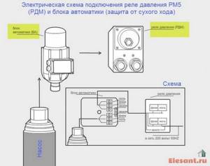
Mixed connection diagram of the automation unit and pressure switch
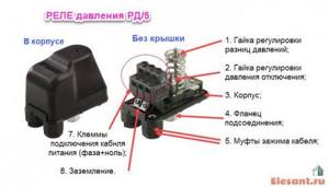
The automation unit protects the pump from running dry (lack of water). This is sometimes not enough. To protect against low water pressure, a pressure switch, for example RD5, is installed in the circuit. Its device is shown in the figure.
The pressure relay and automation unit are included in the circuit like this.
Summary
As you can see, the process of installing and configuring the automation for the pump is not particularly difficult if we are talking about a conventional pressure switch. For future generations of devices, you will have to take the help of a professional or follow the manufacturer's manual.
Recommended Posts
Cast iron bathtubs
Water flows from the tank into the toilet
What to do if the heating battery is leaking
Adjusting the pressure switch for the hydraulic accumulator
Installation of storm drainage systems in apartment buildings
Bathroom at the dacha in a wooden house + photo
Comments
- Quite an informative video, just what you need.
Yulia21.11.2017 at 19:05
Answer
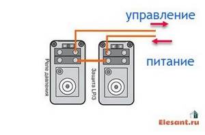
Connection diagram for pressure switch RD5 and protection LP/3
You can simplify the circuit, otherwise reduce its cost, without losing installation quality, by installing an LP/3 protection relay instead of the automation unit. The main disadvantage of this scheme is the need to manually start the pump after shutdown, which is compensated by its low cost.
Pay special attention to connecting RD5 and LP/3 in a single circuit. They are connected in series, that is, when the pressure drops and when running dry (lack of water), the pump turns off. Again, in this scheme the pump is restarted manually.