Functional purpose
Let's start with the fact that there is one very important rule, and if it is not strictly adhered to, the heating system at home will not work well.
This rule states that the diameter of the outlet pipe of a heating boiler should always be equal to or slightly less than the total diameter of all circuits consuming coolant. The best option is if it is larger.
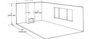
For comparison, here is an example of a wall-mounted unit in which the diameter of the outlet pipe is ¾ inch. Imagine that this boiler will heat three separate circuits:
- The main heating is a radiator system.
- Warm floor.
- An indirect heating boiler that will use water intended for household needs.
Now imagine that each loop is at least ¾ inch in diameter, just like the boiler. But the total figure will be three times greater. That is, no matter how much you want, it will be simply impossible to dispense the required amount of coolant through the diameter of the heating boiler pipe so that it is enough for all three circuits. So much for the reduction in heat transfer throughout the entire area of the house.
Of course, individually all circuits will work fine. For example, the main circuit (radiator) without turning on underfloor heating will completely overpower the heated space. But as soon as you turn on the underfloor heating system, there won’t be enough coolant either here or there. The coolant has enough temperature, but its volume is not enough.
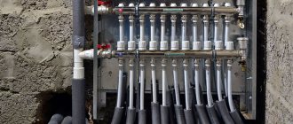
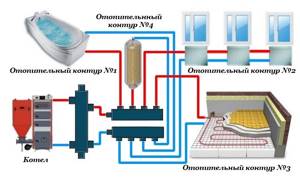
This rather serious problem is solved by installing a distribution manifold in the heating system. In essence, this is a structure made of stainless metal pipes, in the structure of which devices are installed for the input and output of coolant distributed along the circuits. To regulate temperature, pressure, flow volume and its speed, shut-off valves are installed along the terminals, which perform all the necessary functions.
The most important thing is that with the help of a distribution manifold you can control the temperature in a separate room. And this will not affect the neighboring rooms or the temperature of the house as a whole.
Collector device
The collector consists of two pipes:
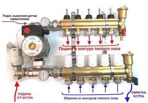
- Connects the supply pipeline from the boiler to the supply circuits of heating systems. This compartment helps distribute hot water. Its device is especially helpful when the question arises of repairing a particular outlet. In this case, on a certain circuit where repair work needs to be carried out, the shut-off valve is closed. It simply shuts off the coolant supply.
- The return compartment regulates the pressure inside each circuit, which ensures the quality of coolant movement. And, therefore, the quality of heat transfer from heating systems.
Anyone who does not understand the essence of installing a distribution manifold begins to build various additional installations into the heating system: a circulation pump, valves for various purposes, and so on. Let's face it, this will not help; they cannot be used to increase the volume of coolant. You will simply make unnecessary expenses that will be in vain.
Attention! If you own a large multi-storey building, it is recommended to install a separate distribution manifold on each floor
What is it needed for
When installing water pressure systems, there is a rule: the total diameter of all branches should not exceed the diameter of the supply pipe.
In relation to heating equipment, this rule looks like this: if the diameter of the boiler outlet fitting is 1 inch, then the system allows two circuits with a pipe diameter of ½ inch. For a small house heated only with radiators, such a system will work effectively. In fact, there are more heating circuits in a private house or cottage: heated floors, heating of several floors, utility rooms, and a garage. When they are connected through a tapping system, the pressure in each circuit will be insufficient to effectively heat the radiators, and the temperature in the house will not be comfortable.
Therefore, branched heating systems are made using collector systems; this technique allows you to adjust each circuit separately and set the desired temperature in each room. So, for a garage, plus 10-15ºС is enough, and for a nursery, a temperature of about plus 23-25ºС is required. In addition, heated floors should not heat up more than 35-37 degrees, otherwise it will be unpleasant to walk on them, and the floor covering may become deformed. With the help of a manifold and shut-off temperature, this problem can also be solved.
Video: using a collector system for heating a house.
Manifold groups for heating systems are sold ready-made, and they can have different configurations and the number of outlets. You can select a suitable collector assembly and install it yourself or with the help of specialists.
However, most industrial models are universal and do not always fit the needs of a particular home. Redesigning or modifying them can significantly increase costs. Therefore, in most cases it is easier to assemble it from separate blocks with your own hands, taking into account the characteristics of a particular heating system.
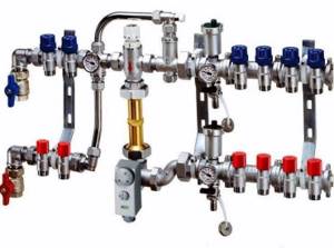
Manifold group for heating system assembly
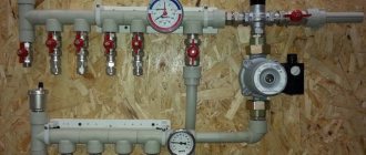
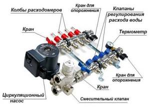
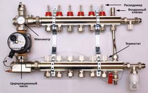
The design of the universal collector group is shown in the figure. It consists of two blocks for forward and reverse coolant flow, equipped with the required number of outlets. Flow meters are installed on the supply (direct) manifold, and thermal heads are located on the return manifold to regulate the return water temperature in each circuit. With their help, you can set the required coolant flow rate, which will determine the temperature in the heating radiators.
The manifold distribution unit is equipped with a pressure gauge, circulation pump and air valves. The supply and return manifolds are combined into one unit with brackets, which also serve to attach the unit to a wall or cabinet. The price of such a unit is from 15 to 20 thousand rubles, and if some of the bends are not used, its installation will be clearly impractical.
The rules for installing the finished block are shown in the video.
Comb - collector unit
The most expensive elements in a manifold distribution block are flow meters and thermal heads. To avoid overpaying for unnecessary elements, you can buy a collector unit, the so-called “comb”, and install the necessary control devices with your own hands only where necessary.
The comb consists of brass tubes with a diameter of 1 or ¾ inches with a certain number of taps with a diameter of ½ inch for heating pipes. They are also connected to each other by a bracket. The outlets on the return manifold are equipped with plugs that allow you to install thermal heads on all or part of the circuits.
Some models may be equipped with taps, with their help you can regulate the flow manually. Such combs have a cast body and are equipped with a fitting/nut thread at the ends, which allows you to quickly and easily assemble a manifold from the required number of branches.
In order to save money, the manifold for heating systems can be assembled from individual elements independently or completely made by hand.
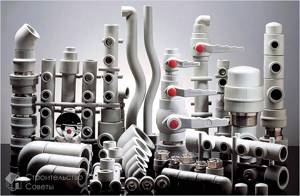
Types of chimneys
Based on the material they are made of, chimneys are divided into aluminum, plastic, and stainless steel. Plastic and stainless steel are popular in Russia.
A gas boiler with a coaxial plastic chimney is usually condensing. The pipe is two-channel, made of heat-resistant plastic. Smoke temperature – up to 205 degrees. Such chimneys are inexpensive, lightweight, and easy to install. The downside is that the durability is not high enough.
Connection to non-condensing type boilers is not recommended, because their temperatures are higher. Conventional chimneys cannot be connected to condensation chimneys.
Stainless steel can withstand temperatures up to 550 degrees, it is durable and acid-resistant. These pipes can be insulated or non-insulated. When installing coaxial chimneys for two-channel gas boilers, thermal insulation is required. The first type has improved aerodynamics, can be used as a collective in an apartment building, and can be connected to boilers with an atmospheric burner. Durability – from 30 years.
The design of a vertical coaxial chimney for a gas boiler involves an outlet along the facade wall to the roof. In other cases, the pipe is routed through an outside wall and ends there.
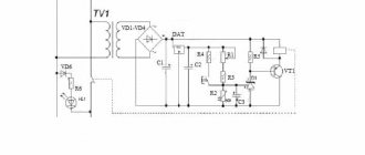
Scheme of a vertical coaxial chimney:
Materials for production
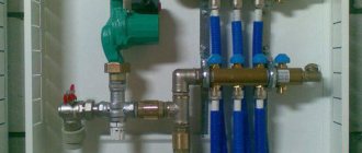
To make a collector unit, you can use pipes: metal (round and rectangular) or polypropylene. The connection of the outlet circuits to the collector pipe is made through ball or valve valves, with the help of which the supply of coolant to each section of the heating system is regulated.
Polypropylene knot
For this, pieces of polypropylene pipe are used, for example, with a diameter of 32 mm (you can use leftovers from the construction of a heating system at home) and several fittings in the form of tees with dimensions 32/32/32 - it is installed at the end of the collector unit, and 32/32/16 - intermediate elements for connecting to outlet channels in sections.
Photo 1. A manifold for a heating system made of polypropylene. The red lines indicate the coolant flow.
The first tee is mounted perpendicular to the main pipe. Its two outer pipes, located vertically, are connected as follows: the air vent is connected to the upper one, and the drain valve is connected to the lower one. A valve or ball valve is mounted to the opposite end of the collector installation. A pipe will go from it towards the boiler.
The intermediate tees are connected into one structure, which will be called a manifold. Therefore, the manifold installation is first assembled by welding tees 32/32/16 with pieces of 32 mm pipes, after which a tee 32/32/32 and a tap are installed on the opposite side. Next, taps or valves for 16 mm pipes are connected to the intermediate fittings. It is with their help that the coolant supply to each circuit will be adjusted.
Advantages of a polypropylene device
First of all, it is necessary to note the low cost of the design, because for this you only have to purchase a small number of tees and taps. Other advantages:
- if the welding is carried out correctly, then such a structure will not leak;
- polypropylene is not subject to corrosion, does not rot and does not change its characteristics under the influence of water and high temperatures;
- light weight of the device;
- ease of installation.
From brass fittings
To assemble such an installation, fittings and valves made of brass are used.
To do this, you need to connect the same tees with double-sided couplings using a threaded connection with mandatory winding of a sealing material on the threads.
Moreover, if the threads on the tees are internal (which is most often the case), then the couplings must have external threads and tightening nuts.
The number of tees is the number of circuits, plus one. The latter is installed at the end of the manifold and is connected by two pipes to a drain valve and an air vent.
From a profile pipe
This is the most difficult process associated with metal welding. This requires skills and experience, because welding two pipes requires complete welding of the joint throughout the entire thickness of the products being connected.
It is recommended to first draw a sketch on paper with a precise definition of the location of the pipes. The pipes used are pipes with a diameter corresponding to the dimensions of the pipes of the outlet circuits. The parameters on paper are transferred to profiled pipes used as a collector. Their cross-section is either 80x80 or 100x100 mm.
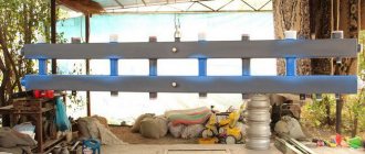
Photo 2. Heating manifold made of profile pipes. Red indicates hot coolant, blue indicates cold fluid.
On one side of them are marked the locations of the pipes with a precise designation of the outer diameter. After that, holes are cut out with a gas cutter or plasma cutter. Spurs are welded to them strictly perpendicularly. At one end, the large pipe is closed with a metal plug (fastening is done by electric welding).
On the other side, a similar plug is installed, in which a hole is pre-cut for connection to a valve or tap. That is, the drive cuts into the hole. Welding areas must be cleaned with a metal brush to remove scale.
Two such elements are connected into one structure by installing metal profiles between them. One is connected to the coolant supply circuit, the second to the return circuit. It is better if you designate different groups with different colors: red is used for supply, blue for return.
Polypropylene pipes manifold Far
Hello dear forum users! Sorry if I'm raising a question that has already been discussed.
New multi-apartment building, polypropylene risers, they decided to make the wiring also with polypropylene (diameter 20). I would like to install Far manifolds. After a long study of forum topics and product range, my head is a mess. We are interested in adjustable collectors 3/4″ 1/2″ outlets (3 - DHW and 2+3 - cold water outlets). As it turned out, the bends come with metric threads and pipe threads; pipe threads are divided into Eurocone and Flat-Faced. Flat-Faced, as I understand it, is ideal for me, but it’s not possible to find them in Rostov (it’s probably too late to order).
Explain what is better to take with TR or MR. As far as I understand, the MR leads are attached via an MR-TR adapter, and on the TR there is already a fitting adapter for soldering polypropylene. With TR, you can straight away fit the fitting, but there are sharp edges that can cut through the gasket.
This is such a mess. Don't throw stones at me, I don't know anything about plumbing.
Those who do the repairs have never done the wiring with the collector, so they made the choice themselves. Today it was proposed to make a prefabricated manifold from polypropylene tees (in one place, the distance between the terminals is minimal, as in a regular manifold (not enough space), i.e., it looks like a regular manifold), and hang taps on the bends. In this regard, more questions have arisen:
- How much less (or more?) reliable will such a collector be?
- Tees are not reinforced, how bad is that? (reinforced pipes)
- The taps on the bends (also made of polypropylene) as far as I understand are ball valves, i.e. Can't regulate? only close - open? Are polypropylene faucets adjustable?
I'm leaning towards Far collectors, but if the connections on the taps are a weak point, maybe a prefabricated one would be better?
www.mastergrad.com
Manufacturing methods
Before you start making a homemade collector, you need to select the material and prepare the necessary equipment. For example, to make a steel model you will need a welding machine. But don’t rush to choose polypropylene. In order to connect polypropylene parts, you will need a special device that is used to weld such pipes. Sometimes it is easier to get an ordinary welding machine than for plastic.
Calculation and distribution of contours
From the very beginning, you need to understand how many heating circuits you will need. It is necessary to take into account each existing heating device, so you will have to evaluate each room according to the list below.
To avoid forgetting anything, use the following list:
- the presence of a “warm floor” system;
- rooms that should have a higher or lower temperature compared to other rooms;
- floor heating;
- heating of each wing.
The rules for manufacturing a heating collector are as follows: the distance between the taps is 10-15 mm, the distance between the supply and return collectors is 25-30 cm.
The diameter of the pipes should be 12.7 mm. The collector itself is made with a diameter of 25.4-38.1 mm, depending on which boiler is installed.
Made from polypropylene
To make a polypropylene manifold assembly with your own hands, you will have to use leftover pipes and fittings.
You will need:
- pipe with a diameter of 32 mm;
- tees 32/32/16 mm.
A tee must be installed on one side. An air vent must be connected to it at the top, and a drain tap at the bottom. On the other side, a valve and pipe are attached. The pipe can be supply or outlet, depending on the purpose of the collector. The supply pipe goes to the boiler.
The remaining outlet with a diameter of 16 mm must be equipped with a valve or flow meter, depending on which collector is for water supply or outlet. At this point the work is completed, and all that remains is to secure the resulting collector systems to the wall using brackets.
Assembly of brass fittings
If a ready-made brass manifold is quite expensive, then you can spend much less money on a homemade one. To build such a structure you will need tees and fittings. They are connected to each other using linen tow or a liquid fixative as a cushioning material. The parts must be connected according to the assembly diagram. An example can be seen in the picture below.
After the collector is assembled, it must be tested. It is difficult to make the connection correctly, so the likelihood of leaks is high.
From a profile pipe
Making a collector from pipes with different cross-sections is the most difficult, since it will require welding work. This model can be called the most “sophisticated”. It is suitable for heating large areas and can have many pipe connections. Often such samples are equipped with a hydraulic arrow.
The following samples will be needed:
- profile pipe 8x8 cm or 10x10 cm;
- round pipe.
The calculation of the pipe cross-section is performed in special programs. It is necessary to set the required heating thermal power, water speed, temperature difference between supply and return.
In this case, you will need to build a circuit, taking into account the number of circuits. Remember that the distance between wiring should be about 15 cm, and between collectors - at least 20 cm. A typical diagram looks like this.
Next, you need to mark a pipe with a rectangular cross-section according to the diagram, and then make holes for wiring using a gas cutter. Weld pre-prepared small parts of threaded pipes to the holes. The block is ready, all that remains is to weld the brackets to it, prepare it and paint it.
What is it needed for
When installing water pressure systems, there is a rule: the total diameter of all branches should not exceed the diameter of the supply pipe. In relation to heating equipment, this rule looks like this: if the diameter of the boiler outlet fitting is 1 inch, then the system allows two circuits with a pipe diameter of ½ inch. For a small house heated only with radiators, such a system will work effectively.
In fact, there are more heating circuits in a private house or cottage: heated floors. heating of several floors, utility rooms, garage. When they are connected through a tapping system, the pressure in each circuit will be insufficient to effectively heat the radiators, and the temperature in the house will not be comfortable.
Therefore, branched heating systems are made using collector systems; this technique allows you to adjust each circuit separately and set the desired temperature in each room. So, for a garage, plus 10-15ºС is enough, and for a nursery, a temperature of about plus 23-25ºС is required. In addition, heated floors should not heat up more than 35-37 degrees, otherwise it will be unpleasant to walk on them, and the floor covering may become deformed. With the help of a manifold and shut-off temperature, this problem can also be solved.
Video: using a collector system for heating a house.
Manifold groups for heating systems are sold ready-made, and they can have different configurations and the number of outlets. You can select a suitable collector assembly and install it yourself or with the help of specialists.
However, most industrial models are universal and do not always fit the needs of a particular home. Redesigning or modifying them can significantly increase costs. Therefore, in most cases it is easier to assemble it from separate blocks with your own hands, taking into account the characteristics of a particular heating system.
Manifold group for heating system assembly
The design of the universal collector group is shown in the figure. It consists of two blocks for forward and reverse coolant flow, equipped with the required number of outlets. Flow meters are installed on the supply (direct) manifold, and thermal heads are located on the return manifold to regulate the return water temperature in each circuit. With their help, you can set the required coolant flow rate, which will determine the temperature in the heating radiators.
The manifold distribution unit is equipped with a pressure gauge, circulation pump and air valves. The supply and return manifolds are combined into one unit with brackets, which also serve to attach the unit to a wall or cabinet. The price of such a block is from 15 to 20 thousand rubles. and if some of the taps are not used, its installation will be clearly impractical.
The rules for installing the finished block are shown in the video.
Comb - collector unit
The most expensive elements in a manifold distribution block are flow meters and thermal heads. To avoid overpaying for unnecessary elements, you can buy a collector unit, the so-called “comb”, and install the necessary control devices with your own hands only where necessary.
The comb consists of brass tubes with a diameter of 1 or ¾ inches with a certain number of taps with a diameter of ½ inch for heating pipes. They are also connected to each other by a bracket. The outlets on the return manifold are equipped with plugs that allow you to install thermal heads on all or part of the circuits.
In order to save money, the manifold for heating systems can be assembled from individual elements independently or completely made by hand.
How the collector works
A group of room heating circuits are brought together. The point of their connection is the collector. Essentially, a manifold for a heated floor is a distribution and mixing unit for performing the following functions:
- regulation of the temperature of the coolant that passes through the boiler heater. (It is enough to supply coolant heated to 45 °C to the underfloor heating system, but this temperature value is low for the heater; usually the minimum value at the inlet to the collector is about 55 °C);
- ensuring the necessary supply of heat energy in each room. In this case, it functions as a mixer and coolant energy regulator for each heating circuit
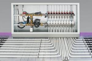
The distribution point for heating circuits is a system consisting of two collectors. It includes a manifold for supplying coolant to the system and a return manifold through which cooled coolant flows. They have pipes through which heated coolant flows from the boiler and cooled coolant is supplied to the boiler for heating. A typical manifold for underfloor heating is shown in the figure below:
The amount of heat entering each circuit is regulated by means of valves with a pressure rod. The design of such regulators allows for energy distribution, both manually and using automation tools, controlled remotely. Heat consumption in the system is controlled by a group of flow meter bulbs. Let's take a closer look at this device:
Please note that the circuit uses a circulation pump. This allows the heating circuit to function more efficiently, since there is not always a need for a high coolant temperature, which simultaneously creates pressure for circulation in the system
The disadvantage is the loss of functional advantage when the power is turned off. In this case, the group of heating circuits becomes incapacitated.
Let's consider the principle of operation of the collector. The coolant received from the boiler heating register carries a certain amount of heat to each circuit of the system through the operation of the circulation pump. This happens when the coolant temperature is higher than the specified value. When the temperature in the system decreases, the three-way valve opens and another portion of heat is added to the system.
When the threshold of the set temperature is reached, the sensor signal will enter the control system, and the three-way valve will shut off the addition of hot coolant.
The circulation pump, operating continuously, and the group of circuits are ensured by the constant movement of the coolant.
To carry out routine maintenance, as well as in case of dismantling, drain taps are provided in the collector.
To prevent airing of the system, air vents can be introduced into the circuit. There is a group of air vents that allow you to automate this process.
What is a mixing unit
The boiler usually heats water to 80-95°C, this is the optimal temperature for use in radiators. However, according to sanitary standards, the floor temperature should not be more than 30°C.
Exceeding this temperature can lead to an increased release of harmful substances from floor coverings, and in general it will be uncomfortable to walk on such a floor (see article on the dangers of heated floors and laminate).
Considering the thickness of the floor screed and floor covering, the temperature of the coolant in the circuits is not higher than 55°C. That is why water for heated floors is supplied through a mixing unit; it mixes hot liquid with cooler liquid (which has already passed through the system and has had time to cool). The system operation diagram is shown in the video:
System elements
When the hot coolant reaches the collector, it rests against the safety valve. The thermal head detects the temperature of the liquid and if it exceeds the set values, the valve opens slightly and the cold and hot coolant are mixed.
In addition, if the circuits are long, they often make a pumping and mixing unit with their own hands. It is equipped with a circular pump that circulates water through itself and increases the pressure in the system.
In addition to the main elements (two- or three-way valve and pump), the unit also contains additional parts: bypass (jumper), drain and shut-off valves, air vent, expansion tank.
As an advice
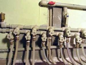
In order to avoid an unesthetic appearance, as in the figure below, it is necessary to carefully approach the issue of pipe lengths when preparing them.
As an example of good work when assembling the distribution unit, the photo below is shown:
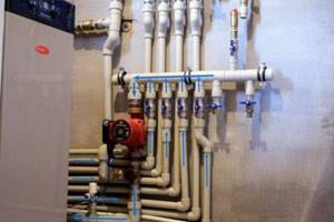
To achieve this result, it is necessary to select the length of the nipples from the pipes, which will ensure a tight fit of the tees.
The photo shows arrows indicating the direction of movement of the coolant. As a rule, it is good form if this is done directly on the pipeline. This makes the distribution node diagram easier to read and understand.
After completing the assembly of the assembly of tees and pipes, it must be secured to the wall. Then you can install the remaining elements: circulation pump, taps, blowers, valves
It is important to remember that heavier parts should be secured directly to the surface and not place stress on the assembly. If necessary, flow meters and control elements can be added to the distributor
Such products can be purchased separately.
Homemade designs
To assemble a homemade unit, you should clearly understand the design of the heating system. It is necessary to become familiar with the principle of operation of collectors and their main purpose. It is also necessary to carry out proper calculations.
Before making a device with your own hands, you need:
- determine the indicators of underfloor heating branches;
- calculate performance indicators, coolant consumption and location of fragments;
- indicate the presence of other heating devices that will be connected to the distribution unit;
- choose a control and regulation system;
- indicate the location of the collector.
It is important to pay attention to the selection of components. They must be designed to function in such heating systems.
The diameter of the distribution manifold is selected so that its cross-sectional area is the same as the cross-sectional area of the pipes.
Assembly from purchased parts
Assembling a distribution unit for a heated floor from purchased parts is not difficult. Each product comes with step-by-step instructions. It contains a drawing.
The coolant pipes are equipped with factory valves and flow sensors. They should be connected if the complete collector is presented in sections with two or three branches.
For ease of assembly, it is recommended to secure the tubes using brackets. Then plugs, connection elements, locking fittings and control devices are installed. The next step is to mount the unit to the wall and install the circulation pump and valve. It is not recommended to install in the reverse order, as it will be difficult to secure the unit.
The pump and valve with a thermal head or servo drive are attached based on a given diagram, after which heating pipes coming from the boiler are connected to them, and heating circuit pipes are connected to the outlets.
Replacing some parts
The factory device is expensive. This explains the attempt to assemble a heated floor manifold with your own hands. It is impossible to make all the components. Some factory items will have to be purchased. When using polypropylene, all parts are soldered taking into account tightness. You should monitor the position of the pipes for ease of connection.
A simple way to assemble a distribution unit is to solder the device from polypropylene pipes and fittings. The required pipe cross-section is 2-3 cm. You will also need tees and bends of the same diameter. The number of fittings, valves and circuits of the heating system must be the same.
First, pipe fragments are measured and cut. The distance between the tees should be small. Then valves, adapters and fittings are welded to the tees for connection to the pump.
A do-it-yourself manifold for heated floors has disadvantages: there is no thermostatic valve or flow sensor on the supply pipe. The system is adjusted manually.
Assembling a manifold with replacement of factory parts is advisable for the simplest heating system circuits. It is recommended to purchase equipment with a complex design in specialized stores.
Modifications of collector units
Before you begin assembling the collector assembly, it is necessary to determine its functional load. The equipment can be installed in several sections of the heating main. Based on this, the necessary equipment, dimensions and level of automation of the work cycle are selected.
In fact, for the full operation of such a node, two devices are needed. Using a comb, the coolant is distributed along the contours of the central supply pipeline. The return collector channel is represented by a collection mechanism and the point of departure of the cooled liquid into the boiler.
The collector heating circuit is selected based on the calculation of the required functionality and installation location. The choice of material for making the device does not affect the number of significant mechanisms
Installation of a homemade distribution group may be required when installing water-heated floors or for preparing standard heating with radiators.
Distinctive features of both options are their sizes and components:
- Boiler room. The welded manifold group is made of pipes with a diameter of up to 100 mm. A circulation pump and shut-off valves are installed on the supply side. The return ring is equipped with shut-off ball valves.
Each of these solutions provides an individual installation scheme. Correct installation of all elements can be carried out only after detailed calculations of all operating point parameters.
The comb can be made of the same material as the pipeline. If it is different, adapters will be used to connect the collector
There are also differences in the required number of circulation pumps. In the boiler room, each line is equipped with this device. For heated floors, only one installation is provided.
How to tighten fittings for a metal-plastic pipe on a heated floor manifold
How tightly and with what can you tighten the fittings for metal-plastic pipes on the underfloor heating manifold?
I work with metal-plastic with this key,
The “sponges” are thinner and can be spread out easily and quickly to suit any number.
In general, the nut on the fitting depends on the diameter of the pipes.
Most often, for heated floors, a metal-plastic pipe is used, 16 mm, less often 20 mm.
The keys, if we talk about open-end ones, are on the 24th, 27th.
Is the manifold also for metal-plastic pipes?
If the pipes are connected, for example, to a polypropylene manifold,
Again, there are subtleties, do we go through “father” or through “mother”?
You need to know this in order to advise which key is more convenient to work with.
In general, buy the universal one I mentioned above (preferably two), suitable for any pipes, with any fittings.
This key is even convenient for holding the polypropylene manifold on which the metal-plastic fitting will be mounted.
www.remotvet.ru
Necessary materials and equipment
So, to connect a warm water floor you will need:
- special pipes;
- collector;
- thermal insulation.
All these materials and equipment are equally important in the structure of a warm water floor. Let's talk about each point in detail
Pipes
In order to install a warm water floor, you will need pipes reaching two centimeters in diameter. As for the pipe material, reinforced polyethylene or multilayer (or otherwise metallized) pipes are suitable. Ideally, pipes should have an anti-oxygen coating.
Why is it better to choose pipes made from synthetic materials? Firstly, it will be easier for you to install just such pipes with your own hands, and secondly, the inner surface of pipes made from such materials is smooth, they do not cause electrochemical corrosion.
How to calculate how many pipes it will take to install a warm water floor? It's not difficult at all! If the distance between the pipes is 20 centimeters, then for each square meter of living space it is necessary to take five meters of linear pipes
Please note that the longest continuous length of the so-called “loop” in the system is 80-120 meters
While you are installing the pipes with your own hands, pay attention to the fact that next to the walls and windows the pipes must be laid more tightly, at a distance of not 20, but 10-15 centimeters from each other. Ideally, you can also plan how the furniture will be arranged in the living space after the renovation work is completed. For example, if you want to install a stationary cabinet in a room, then you don’t have to lay pipes under it
For example, if you want to install a stationary cabinet in a room, then you don’t have to lay pipes under it
Ideally, you can also plan how the furniture will be arranged in the living space after the renovation work is completed. For example, if you want to install a stationary cabinet in a room, then you don’t have to lay pipes under it.
The rules for connecting a warm water floor also require compliance with the following parameters:
- the operating pressure should be approximately 10 bar (1 bar error allowed);
- The highest coolant temperature should be +100 °C.
Collector
The manifold is the most complex part of a heated floor. The complexity of this object is also reflected in its price, so it is a reasonable decision to make the collector yourself. The type of collector depends on the number of pipe inlets and outlets.
Thermal insulation
As for thermal insulation boards, they can be equipped with pipe clamps or have markings. When using foam plastic during installation, it must be covered with waterproofing, that is, a polyethylene film.
Why is thermal insulation needed? It is necessary so that the heat does not escape downwards, otherwise you will heat the floors between floors. Thermal insulation must completely cover the entire floor of the living space.
In addition to the above materials and equipment, installation of heated floors will also require:
- fittings to connect pipes and manifold;
- a reinforcing mesh made of metal with cells measuring approximately three to five centimeters (the mesh is necessary to fill the screed);
- pipe fasteners;
- damper tape (the required length of the tape is equal to the perimeter of the room).
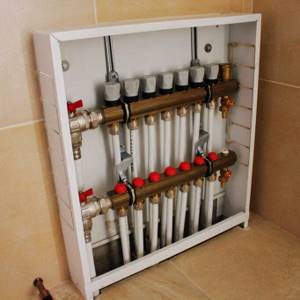
Manifold cabinet: purpose, types and advantages
Manifold cabinet
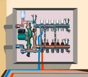
The manifold cabinet is a protective structure that protects the mixing unit from outside interference. Essentially, this is a box installed in a horizontal position, equipped with fastening mechanisms and a door.
The use of such a cabinet makes it possible to place the manifold unit in a convenient place without damaging the interior and technical content. Thus, the collector-mixing unit can be placed in any room without fear that children and pets will be interested in the contents.
There are two types of manifold cabinets:
- External ones are mounted on the wall surface using special fasteners and legs (if necessary, height adjustments). The outlet slots are covered with removable metal plates. The cabinet itself is coated with powder paint or an anti-corrosion compound on the sides; the door can be white, beige or another color according to the consumer’s taste.
External manifold cabinet
- Built-in ones are installed in a niche or covered with clapboard or plasterboard. The side parts, as a rule, are not painted, since they contain fastening and outlet spans. The facade is painted white, but options are also possible.
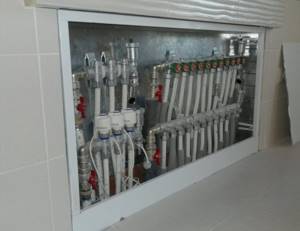
Built-in manifold cabinet
Both types of structures must have a strong lock and protection against possible thermal burns. Cabinets are not placed below floor level, but are not raised too high. After installing the box, the process of assembling the water floor collector proceeds according to the planned diagram. At the same time, all bends remain easily accessible for laying contours.
You can also place a water supply meter inside the cabinet, combining all the circuits at one point. On the wall, the entire structure will look many times more aesthetically pleasing than a bunch of pipes for the water circuit of a heating system with numerous sensors, valves and taps.
Installation nuances
The technology for attaching the collector to the wall is quite simple: the TC and radial distribution comb are suspended on mounting brackets, the loops are connected with Eurocone fittings. Pipes going to the top of the collector (usually the “return”) are passed under the bottom.
Advice. No one is forcing you to mount the distributor on brackets. If necessary, the tubes can be spread apart and mounted separately on the wall. The collector box is used in residential areas; when installing the collector in the boiler room, the cabinet is not needed.
Let's briefly list the main points:
- The size of the comb is selected according to the diameter of the pipes used in the heating loops - Ø16 or Ø20 mm. Accordingly, we take a ¾ or 1 inch distributor. The material of the product does not matter; in terms of price/quality ratio, stainless steel wins.
- If the number of comb outlets exceeds 12, assemble a collector assembly of 2 sections. When installing accessories, winding materials are not used, since the parts are equipped with rubber seals.
- A heavier common house collector is suspended on hooks, reinforced brackets, or installed on the floor. Pumps, pipes and other piping elements must not load the distributor with their own weight.
- The hottest coolant receives an indirect heating boiler. The coil and circulation pump of the water heater are connected to the comb directly, usually from the end.
- The radiator heating and TP branches are connected to the manifold through mixing units with three-way valves. A separate pump is installed on each line, selected for pressure and performance.
Polypropylene manifold
Polypropylene is successfully used in modern heating systems. With the correct calculation of the pipe diameter, you can make a warm floor from polypropylene pipes.
For more information on how to make a polypropylene heated floor, read this article “Warm floor from polypropylene pipes.”
A distribution manifold can also be assembled from polypropylene fittings. To do this you will need the following components:
- Pipes Ø25 and Ø32 mm.
- Plugs Ø32 mm.
- Couplings 32×1″ and 25×3/4 with internal thread.
- American ball valves.
- Couplings 25×3.4 with external thread.
- Security group.
- Tees Ø25 and Ø32 mm.
- Sealant.
- Automatic air vent.
Main characteristics of the collector system
The main difference between the collector and standard linear method of redistribution of the coolant is the division of flows into several channels independent of each other. Various modifications of collector installations can be used, differing in configuration and size range.
The collector heating circuit is often called radiant. This is due to the design features of the comb. When examining the device from the top point, you will notice that the pipelines extending from it resemble an image of sun rays
The design of the welded manifold is quite simple. The required number of pipes is connected to the comb, which is a round or square pipe, which, in turn, are connected to individual lines of the heating circuit. The collector installation itself is interfaced with the main pipeline.
Shut-off valves are also installed, through which the volume and temperature of the heated liquid in each of the circuits is regulated.
A manifold group, complete with all the necessary parts, can be purchased ready-made or assembled independently, which will significantly reduce the cost estimate when designing heating
The positive aspects of operating a heating system based on a distribution manifold are the following:
- The centralized distribution of the hydraulic circuit and temperature indicators occurs evenly. The simplest model of a two- or four-circuit ring comb can balance the indicators quite effectively.
- Regulation of heating main operating modes. The process is reproduced due to the presence of special mechanisms - flow meters, mixing unit, shut-off and control valves and thermostats. However, their installation requires correct calculations.
- Ease of maintenance. The need for preventive or repair measures does not require shutting down the entire heating network. Due to the sliding pipeline fittings mounted on each individual circuit, you can easily shut off the coolant flow in the required area.
However, there are also disadvantages to such a system. First of all, pipe consumption increases. Compensation for hydraulic losses is carried out by installing a circulation pump. It must be installed on all collector groups. In addition, this solution is only relevant in closed-type heating systems.
Heating circuit elements
Modern heating, which uses heating collectors, involves the creation of a large structure, which includes the following main elements:
- Source of thermal energy
. It is the first starting point from which the heated coolant is directed into pipelines and heating radiators. The power of heating units must be calculated as accurately as possible so that the equipment functions in accordance with its intended purpose.
The process of choosing a boiler and calculating its parameters is a very important point when creating a heating structure. An underestimated power indicator will not allow the circuit to work fully, as a result of which the rooms will not be warm enough. An overestimated value of the required heat transfer will lead to excessive fuel consumption, which will require the installation of control elements and, accordingly, additional financial costs;
Circulation pump
. A closed heating circuit with a comb requires forced circulation of the coolant. To do this, install circulation pumps in the heating system. thanks to which the necessary pressure is created to move the heated liquid, an optimal temperature is ensured, guaranteeing high-quality work.
When choosing a circulation pump, according to the instructions, a number of parameters are taken into account. The motor power of the circulation device is not one of the main indicators; it just determines the amount of energy consumed by the motor
Attention should be paid to the speed and volume of pumped liquid per unit of time
Pumps must be selected very carefully. The fact is that to ensure high-quality heating, it is necessary to select it with a power reserve that exceeds the design parameters by about 10 percent, since property owners often add a heating area without replacing the circulation device.
Cabinets
. This type of heating structure requires hiding its components, such as a do-it-yourself heating manifold, pipelines, ball valves, in drawers or cabinets specially equipped for this. They are either fixed outside or built into the walls.
What is a heating collector
The device is structurally made in the form of a metal comb, equipped with several “input-output” points, which autonomously connect heating batteries to the in-house coolant.
The purpose of this connection is to adjust and control heating parameters:
- volume of network water;
- network temperatures;
- pressure in the supply and return networks.
The design of the heating unit controls heat transfer and ensures sanitary and hygienic living standards in the premises.
Important! For heating installation in two-story buildings, the unit is mounted on each floor, thus implementing a high-quality heat supply scheme with floor-by-floor regulation
Boiler repair
In case of leakage, we repair fire tube boilers in the following sequence:
- We study the documentation and diagrams of the device.
- We search for the problem area and localize it.
- We clean the surface near the crack to bare metal to a width of 15-20 mm.
- We carry out welding work at ambient temperatures above +5C. We use electrodes with a thickness of 2.5 mm or 3 mm. We weld the seam from the side of the drum 2-4 mm larger than from the pipe. The welding direction is from the middle of the crack to the edges using two welding machines simultaneously.
- We clean the seam until it shines and look at its quality. If necessary, we eliminate deficiencies: uncooked areas and shells.
- We test the boiler.
Fire-tube water-heating boilers are used in boiler houses, for heating private households, in industry and other areas.
Sometimes in the construction of fire-tube boilers, due to improper operation, it becomes necessary to replace the damaged section. For these purposes, the gas-flame method is used. In this case, the dimensions of the damaged part must be at least 200 mm or the diameter of the pipe. First, they localize the area, then cut it out with a grinder until the thickness and properties of the metal are preserved, after which they clean and weld a patch made of steel of the same composition.
Fire-tube water heating boilers are used in boiler houses, for heating private households, in industry and other areas. This is due to their high heating efficiency and economical fuel consumption, reliability and ease of operation. The design of fire tube boilers is relatively simple, so they can be easily repaired even independently without the involvement of specialists.
How to make a heating collector with your own hands?
Today, the main requirement for heating systems is their energy efficiency. The optimal heating options are considered to be connection diagrams for heating devices that provide a comfortable microclimate in the house during the winter cold, and also guarantee rational consumption of energy resources, affordable heating costs and rationality. The collector heating system of a private house, which has other advantages, fits this description. These include practicality, functionality, ease of use and reliability.
Radial scheme and heated floor
The radial scheme allows you to combine a homemade heating collector and a “warm floor” system. But this design has a number of features.
Before you begin to create it, you need to familiarize yourself with them:
- the heating manifold must be installed on the condition that it is equipped with control valves and thermostatic valves on absolutely all circuits;
- When laying pipes for a “warm floor” heating system, electrothermal drives and thermostatic heads are certainly used. Thanks to these devices, “warm floors” will be able to quickly respond to changes in temperature and maintain the necessary microclimate in each room;
- The option for arranging a distribution system can be different - standard (made according to a standard scheme) and individual. The last method deserves special attention. In this case, the boiler operates in normal mode without significant temperature changes, and fuel is consumed economically.