Thermostats are widely used in modern appliances, automobiles, heating and air conditioning systems, manufacturing, refrigeration and furnace applications. The operating principle of any thermostat is based on turning on or off various devices after reaching certain temperature values.
Modern digital thermostats are controlled using buttons: touch or regular. Many models also come with a digital panel that displays the set temperature. The group of programmable thermostats is the most expensive. Using the device, you can provide for temperature changes hourly or set the required mode for a week in advance. The device can be controlled remotely: via a smartphone or computer.
For a complex technological process, for example, a steel-smelting furnace, making a thermostat with your own hands is a rather difficult task that requires serious knowledge. But any home craftsman can assemble a small device for a cooler or incubator.
In order to understand how a temperature controller works, consider a simple device that is used to open and close the damper of a mine boiler and is activated when the air is heated.
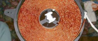
To operate the device, 2 aluminum pipes, 2 levers, a return spring, a chain that goes to the boiler, and an adjustment unit in the form of a faucet axle box were used. All components were installed on the boiler.
As is known, the coefficient of linear thermal expansion of aluminum is 22x10-6 0C. When an aluminum pipe with a length of one and a half meters, a width of 0.02 m and a thickness of 0.01 m is heated to 130 degrees Celsius, an elongation of 4.29 mm occurs. When heated, the pipes expand, causing the levers to shift and the damper to close. When cooling, the pipes decrease in length, and the levers open the damper. The main problem when using this scheme is that it is very difficult to accurately determine the response threshold of the thermostat. Today, preference is given to devices based on electronic elements.
Scheme of operation of a simple thermostat
Typically, relay-based circuits are used to maintain a set temperature. The main elements included in this equipment are:
- temperature sensor;
- threshold circuit;
- actuator or indicator device.
Semiconductor elements, thermistors, resistance thermometers, thermocouples and bimetallic thermal relays can be used as sensors.
The thermostat circuit reacts when the parameter exceeds a given level and turns on the actuator. The simplest version of such a device is an element based on bipolar transistors. The thermal relay is based on a Schmidt trigger. A thermistor acts as a temperature sensor - an element whose resistance changes depending on the increase or decrease in degrees.
R1 is a potentiometer that sets the initial offset on thermistor R2 and potentiometer R3. Due to the adjustment, the actuator is activated and relay K1 is switched when the resistance of the thermistor changes. In this case, the operating voltage of the relay must correspond to the operating power supply of the equipment. To protect the output transistor from voltage surges, a semiconductor diode is connected in parallel. The load value of the connected element depends on the maximum current of the electromagnetic relay.
Attention!
On the Internet you can see pictures with thermostat drawings for various equipment. But quite often the image and description do not correspond to each other. Sometimes the pictures may simply show other devices. Therefore, production can begin only after carefully studying all the information.
Before starting work, you should decide on the power of the future thermostat and the temperature range in which it will operate. The refrigerator will require some elements, and the heating will require others.
Creating a simple thermostat
When repairing household electrical appliances, you may have encountered a situation where the thermostat failed. Although this is a small microcircuit installed to control the amount of heating or cooling of something.
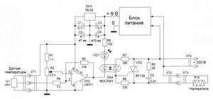
Alas, the cost of such a factory-made element is quite high, so it is much more profitable to assemble the thermostat yourself. A diagram of a fairly simple homemade thermostat is shown in the figure below.
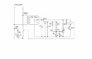
Rice. 5. Diagram of a simple thermostat
To make it you will need:
- step-down transformer from 220 to 12 V;
- six diodes (in this example, IN4007 are used);
- capacitors 47 µF, 1 mF and 2 mF;
- microcircuit for a 5V stabilizer;
- transistor (in the example under consideration it is KT814A);
- Variable zener diode (TL431);
- resistive elements at 4.7; 160, 150 and 910 kOhm;
- resistor with variable resistance 150 kOhm;
- temperature dependent resistor 50 kOhm;
- Light-emitting diode;
- electromagnetic relay 100 mA with a supply voltage of 12V (in the example under consideration, an automobile version is used);
- button and body.
The manufacturing process consists of the following stages:
- Using a soldering iron, assemble the above parts onto a printed circuit board as shown in the diagram above.
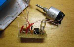
- After this, take the measuring element for the thermostat out into the open space to install it in the desired location.
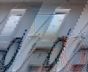
Rice. 6. Output the measuring element
- Install a variable resistor on a rigid frame and apply a temperature scale to set up the device.
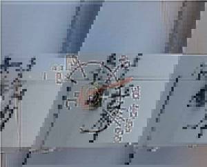
Rice. 7. Install the regulator on the frame and apply the graduation
- Connect the power cord to the terminal block.
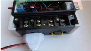
Connect the power cord to the terminal block.
In this case, the terminal block was taken from an old device located in the housing.
- Connect all separately placed elements to the board and cover with the housing.
After assembling the thermostat, it can be installed in any place, for example, for heating and connected to the power circuit of an electric boiler. If the heating radiators heat the room to the set temperature, the relay contacts will break the circuit and stop the power supply. When the digital thermometer cools down, the heating will turn on again and heat up again. If you are not satisfied with the temperature regime, you can change it by setting the sensor.
Three element thermostat
One of the elementary devices, using an example of which you can assemble and understand the principle of operation, is a simple do-it-yourself thermostat designed for a fan in a PC. All work is done on a breadboard. If there are problems with the pin, then you can use a solderless board.
The thermostat circuit in this case consists of only three elements:
- power MOSFET transistor (N channel), you can use IRFZ24N MOSFET 12 V and 10 A or IFR510 Power MOSFET;
- potentiometer 10 kOhm;
- NTC thermistor 10 kOhm, which will act as a temperature sensor.
The temperature sensor reacts to an increase in degrees, due to which the entire circuit is activated and the fan turns on.
Now let's move on to the setup. To do this, turn on the computer and adjust the potentiometer, setting the value for the fan turned off. At the moment when the temperature approaches critical, we reduce the resistance as much as possible before the blades rotate very slowly. It is better to do the setup several times to make sure the equipment is working effectively.
The modern electronics industry offers elements and microcircuits that differ significantly in appearance and technical characteristics. Each resistance or relay has several analogues. It is not necessary to use only those elements that are indicated in the diagram; you can take others that match the parameters of the samples.
Setting up the thermostat
As already mentioned, a thermostat based on the LM335 sensor does not need adjustment. It is enough to know the voltage supplied by the potentiometer to the direct input of the comparator.
It can be measured using a voltmeter. The required voltage value is determined by the above formula.
If you need, for example, for the device to operate at a temperature of 20 degrees, it should be 2.93 V.
If any other element is used as a temperature sensor, the reference voltage will have to be checked experimentally. To do this, you need to use a digital thermometer, for example, TM-902S. For precise adjustment, the thermometer and thermostat sensors can be connected using electrical tape, after which they are placed in an environment with different temperatures.
Thermostat made from scrap materials
The potentiometer knob must be rotated smoothly until the thermostat operates. At this moment, you should look at the scale of the digital thermometer and apply the temperature displayed on it to the scale of the thermostat. You can determine extreme points, for example, for temperatures of 8 and 40 degrees, and mark intermediate values by dividing the range into equal parts.
If you don’t have a digital thermometer at hand, the extreme points can be determined by water with ice floating in it (0 degrees) or boiling water (100 degrees).
When faced with choosing a heater, people discover that there are many types of devices, but you need to choose one. Ceramic heater for the home - subtleties of the right choice, review of models and prices.
Air humidity standards and methods for measuring it are presented in this topic.
Thermostats for heating boilers
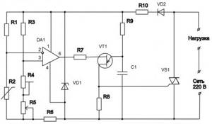
When adjusting heating systems, it is important to accurately calibrate the device. To do this you will need a voltage and current meter. To create a working system, you can use the following diagram.
Using this scheme, you can create external equipment for monitoring a solid fuel boiler. The role of the zener diode here is performed by the K561LA7 microcircuit. The operation of the device is based on the ability of a thermistor to reduce resistance when heated. The resistor is connected to the electricity voltage divider network. The required temperature can be set using variable resistor R2. The voltage is supplied to the 2I-NOT inverter. The resulting current is supplied to capacitor C1. A capacitor is connected to 2I-NOT, which controls the operation of one trigger. The latter is connected to the second trigger.
Temperature control proceeds according to the following scheme:
- as the degrees drop, the voltage in the relay increases;
- when a certain value is reached, the fan that is connected to the relay turns off.
It is better to solder on a mole rat. As a battery, you can take any device operating within 3-15 V.
Carefully!
Installing homemade devices for any purpose on heating systems can lead to equipment failure. Moreover, the use of such devices may be prohibited at the level of services providing communications in your home.
Purpose of thermostats
Any electric or gas boiler is equipped with an automation kit that monitors the heating of the coolant at the outlet of the unit and turns off the main burner when the set temperature is reached. Solid fuel boilers are also equipped with similar means. They allow you to maintain the water temperature within certain limits, but nothing more.
In this case, the climatic conditions indoors or outdoors are not taken into account. This is not very convenient; the homeowner has to constantly select the appropriate operating mode for the boiler on his own. The weather can change during the day, then the rooms become hot or cool. It would be much more convenient if the boiler automation was oriented towards the air temperature in the rooms.
To control the operation of boilers depending on the actual temperature, various heating thermostats are used. Being connected to the boiler electronics, such a relay turns off and starts heating, maintaining the required temperature of the air, not the coolant.
Digital thermostat
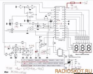
In order to create a fully functioning thermostat with accurate calibration, you cannot do without digital elements. Consider a device for monitoring temperatures in a small storage area for vegetables.
The main element here is the PIC16F628A microcontroller. This chip provides control of various electronic devices. The PIC16F628A microcontroller contains 2 analog comparators, an internal oscillator, 3 timers, CCP comparison modules and USART data transfer exchange modules.
When the thermostat is operating, the value of the existing and set temperature is supplied to MT30361 - a three-digit indicator with a common cathode. In order to set the required temperature, use the following buttons: SB1 – to decrease and SB2 – to increase. If you carry out the adjustment while simultaneously pressing the SB3 button, you can set the hysteresis values. The minimum hysteresis value for this circuit is 1 degree. A detailed drawing can be seen on the plan.
When creating any of the devices, it is important not only to correctly solder the circuit itself, but also to think about how best to place the equipment. It is necessary that the board itself is protected from moisture and dust, otherwise short circuits and failure of individual elements cannot be avoided. You should also take care to insulate all contacts.
Simple DIY thermostat - diagram
The design of the thermostat is not particularly complicated, so many novice radio amateurs hone their skills in the manufacture of this device. A variety of circuits are offered, but the most widely used option is the use of a special microcircuit called a comparator.
This element has two inputs and one output. One input is supplied with a certain reference voltage, which corresponds to the required temperature, and the second input is supplied with voltage from the temperature sensor.
Thermostat circuit for heated floors
The comparator compares the incoming data and, at a certain ratio, generates an output signal that opens a transistor or turns on a relay. In this case, current is supplied to the heater or refrigeration unit.
Video
The reason for assembling this circuit was the breakdown of the thermostat in the electric oven in the kitchen. Having searched on the Internet, I didn’t find a particular abundance of options on microcontrollers, of course there are some, but all are mainly designed to work with a temperature sensor like DS18B20, and it is very limited in the temperature range of upper values and is not suitable for the oven. The task was to measure temperatures up to 300°C, so the choice fell on K-type thermocouples. Analysis of circuit solutions led to a couple of options.
Connection diagram
The manufacturer must include detailed instructions with each thermostat, which describe step by step how to properly connect the thermostat and how to use it. But there are some general installation rules that must be followed if you need to connect the thermostat yourself.
Most thermostats are designed to operate from a 220 V network connection. Before connecting, you need to make sure that this indicator corresponds to reality. It is best if the sockets and the sensor itself are fixed at the same level at a height of approximately one and a half meters from the floor
If the outlets are located higher or lower, you should use an extension cord. It is important to position the thermostat so that it is not located next to the front door, window or any heating appliances. Such temperature changes will distort the real data, and as a result the thermostat will not work correctly. Before connecting the thermostat, you need to check the serviceability of the socket, as well as the heater itself.
All components of such a heating system must only be in good condition. As soon as the installation of the thermostat is completed, you must immediately program it for further operation - that is, set the settings.
It is worth remembering that before proceeding with the actual installation of a thermostat of any type, you need to make sure that you have all the necessary components on hand.
You can learn how to choose a room thermostat for a heater from the video below.
Thermostat circuit - second option
After some thought, I came to the conclusion that it is possible to connect here the same controller as on the soldering station, but with a little modification. During the operation of the soldering station, minor inconveniences were identified: the need to set the timers to 0, and sometimes an interference occurs that puts the station into SLEEP
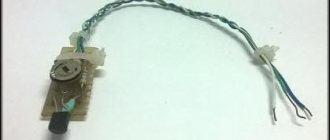
. Considering that women do not need to remember the algorithm for switching the timer to mode 0 or 1, the circuit of the same station was repeated, but only the hair dryer channel. And minor improvements led to stable and “interference-free” operation of the thermostat in terms of control. When flashing AtMega8 firmware, you should pay attention to the new fuses. The following photo shows a K-type thermocouple, which is convenient to mount in the oven.
I liked the work of the temperature controller on the breadboard and started final assembly on the printed circuit board.
I finished the assembly, the operation is also stable, the readings in comparison with the laboratory thermometer differ by about 1.5°C, which is basically excellent. When setting up, there is an output resistor on the printed circuit board; I have not yet found an SMD of this value in stock.
The LED models the heating elements of the oven. The only note: the need to create a reliable common ground, which in turn affects the final measurement result. The circuit requires a multi-turn tuning resistor, and secondly, pay attention to R16, it may also need to be selected, in my case it is 18 kOhm. So, here's what we have:
In the process of experimenting with the latest thermostat, more minor improvements appeared that qualitatively affected the final result, look at the photo with the inscription 543
- this means the sensor is disconnected or broken.
And finally we move from experiments to the finished design of the thermostat. I implemented the circuit into the electric stove and invited an authoritative commission to take over the work :) The only thing that my wife rejected were the small buttons on the convection control, general power supply and airflow, but this can be solved over time, but for now it looks like this.
The regulator maintains the set temperature with an accuracy of 2 degrees. This happens at the moment of heating, due to the inertia of the entire structure (the heating elements cool down, the internal frame is temperature equalized), in general, I really liked the scheme in the work, and therefore it is recommended for independent repetition. Author - GOVERNOR
.
Discuss the article THERMOREGULATOR DIAGRAM
Thermostats are widely used for various purposes: in cars, heating systems of various types, refrigerators and furnaces. Their job is to turn off or turn on devices after reaching a certain temperature. It’s not difficult to make a simple mechanical thermostat with your own hands. Modern designs have a more complex design, but with some experience it is possible to make analogues of such structures.
- Show all
A little theory
Any thermostat structurally includes three main blocks:
- measuring;
- logical;
- executive.
Theoretically, a temperature sensor can be represented by a set of four resistances, among which three resistors will be represented by elements with constant electrical parameters, and the fourth by variable ones. They are assembled into a measuring half-arm circuit shown in Figure 1 below:
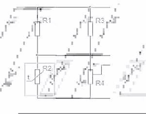
Rice. 1. Sensor made of half-arm resistors
The diagram shows the principle of connecting resistors to obtain a temperature sensor. As you can see, resistance R2 is variable and changes its physical value in accordance with changes in ambient temperature. When the same supply voltage is supplied to the thermostat, when the resistance in the arm changes, the current in the circuit will increase.
Based on the changes, temperature fluctuations are analyzed, as a result of which the working element causes the thermostat to operate and subsequently turn off or turn on the equipment.
To measure the resistance of resistors, a microcircuit operating in comparator mode is installed as a logical element. Its task is to compare the electrical signals in the two arms. An example of a temperature controller circuit is shown in the figure:
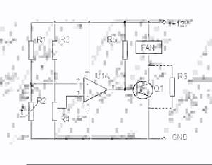
Rice. 2. Schematic diagram of the thermostat
Here, the U1A microcircuit block receives signals from the temperature meter at inputs 2 and 3. When the response temperature is reached, different currents will begin to flow in the arms, and the comparator will send a signal to turn on to the control element of the electronic thermostat.
When the thermometer sensor cools down, the current in the arms of the thermostat will equalize, and the electronic unit will issue a control signal to turn off. The above electronic circuit operates in two stable states - off and on, alternating operating modes occurs in accordance with a given logic.
This thermostat circuit is used in the operation of a personal computer cooler; receiving power from the power supply, the current in the arms is compared. When the power supply overheats, the thermostat will switch the transistor to the opposite state and the fan will start.
This principle can be used not only in fans, but also in a number of other devices:
- to control the operation of electric heating based on temperature readings in the room;
- to set the temperature level in a homemade incubator;
- when connecting a heated floor to control its operation;
- to set the temperature range of engine operation, with forced cooling or shutting down the system when the temperature limit is reached;
- for soldering stations or hand soldering irons;
- in cooling systems and refrigeration equipment with the logic of reducing temperature within certain limits;
- in ovens and stoves for both household and industrial purposes.
The scope of application of the thermostat is not limited in any way; wherever you want to control the temperature level in automatic mode with power management, such a device will be an excellent assistant.
Mechanical thermostat
Today, the newest models of thermostats are controlled using touch buttons, while older models are controlled by mechanical ones. Most of these devices have a digital panel that displays the temperature of the coolant in real time, as well as the required maximum degree.
The production of such devices is not complete without programming them, so their price is very high. They allow you to adjust the temperature according to different parameters, for example, by hour or day of the week. The temperature will change automatically.
If we talk about thermostats for industrial steel furnaces, it will be difficult to make them yourself, since they have a complex design and require the attention of more than one specialist. These are mostly made in factories. But making a simple temperature controller with your own hands for an autonomous heating system, incubators, etc. is not a difficult task. The main thing is to adhere to all drawings and production recommendations.
In order to understand how the thermostat works, you can disassemble a simple mechanical structure. It works on the principle of opening and closing the door (damper) of the boiler, thereby reducing or increasing the access of air to the combustion chamber. The sensor reacts, of course, to temperature.
To produce such a device you will need the following components
:
- return spring;
- two levers;
- two aluminum tubes;
- adjusting unit (looks like a crane axle box);
- a chain that connects two parts (thermostat and door).
All components must be assembled and mounted on the boiler.
The device works thanks to the property of aluminum to expand under the influence of temperature. In this regard, the damper closes. If the temperature decreases, the aluminum pipe cools and decreases in size, so the damper opens slightly.
But this scheme also has its significant disadvantages. The problem is that it is difficult to determine when the damper will operate this way. To approximately adjust the mechanism, precise calculations are needed. It is impossible to determine exactly how much an aluminum pipe will expand. Therefore, in most cases, devices with electronic sensors are now preferred.
Homemade mechanical thermostat for a mine boiler
Add a link to a discussion of the article on the forum
RadioKot >Schemes >Digital devices >Household appliances >
| Article tags: | Add a tag |
Thermostat for gas boiler V2, plus weather control.
Author: [email protected] Published 05/24/2012 Created with the help of KotoEd.
Update, previous version of the Thermostat diagram for gas boiler V1, plus weather control, since this update appeared in the summer, we will use the device according to the saying Prepare a sleigh in the summer, and a cart in the winter.
This circuit is designed to maintain and regulate indoor temperature. Each gas wall-mounted boiler provides for the connection of such a thermostat; the circuit is connected in the boiler to special terminals for an external remote thermostat.
The main purpose of this scheme is to use this type of regulation so that at positive temperatures the boiler does not overuse fuel for unnecessary overheating, and smoothes out noticeable temperature changes in the room during the autumn-spring heating season; in winter at low negative temperatures, the program makes virtually no changes in heating mode.
Scheme:
The main elements of the scheme are; LCD 16x2 based on controller HD44780 or KS0006, MK ATmega8 with any letter and housing.
Temperature sensors DS18b20.
Photoresistor (any one that is called such :))).
In my version of the circuit, it is used to reduce the voltage from the power supply Step-down converter on the MC34063 chip, this slight complication of the circuit is determined by the fact that the entire circuit is powered from 24 volts, plus the LCD backlight is constantly connected, to “crank” these conditions, figuratively speaking "hot"....
If you have a power supply voltage of up to 15 volts, and you do not plan to connect an LCD backlight, there are no obstacles, use a 5 volt linear stabilizer of the “crank” type as stabilization.
The principle of operation of the circuit.
Thermostat U-2 (street) always works, until the Toff period... (see), if you want to use only thermostats in the circuit, the operation of the timers can be stopped forcibly by setting the jumper (MK port PD3) to the common power supply.
Thermostat U-1 (room) always if the temperature is below the set room temperature. And in parallel, U-2 can always turn on the heating command..
Thermostat U-3 (installed at the coolant inlet to the boiler (return)) has priority over U-1 and U-2 in case of overheating, and will always turn off the command sent to the boiler for heating, that is, the command from U-1 and U-2. (commands from U-3 have priority over the operation of U-2 timers and over data from U-1).
And also if there was activity in thermostats U-1 and U-3, thermostat U-2 -> pause period timer starts counting the % charge interval from zero..
The time modes of the timers in relation to the outside temperature can be clearly seen on. According to the graph, we see that for the timer “ (red line), the further the street temperature is from what is comfortable for a person, the stronger the bend in the line displaying the temporary operation of the timer “ . This software construction of the work schedule is based on the standard calculated heat loss of the room, compensated by heating. Determined from the heat balance of the heated room (SNiP 2.08.01-89 heating of residential buildings (in a simplified form)).
Using a photo sensor, the circuit determines the time of day, and based on this, the temperature graph shifts by 2°C.
In the V-2 version of the program, a change in the set coolant temperature by +x°C in relation to the outside temperature has been added (when the outside air temperature decreases, depending on the outside temperature, from 0 to 6° is automatically added to the set coolant temperature C (see).
Resistor divider (PC3 port) during normal operation of the circuit at the measuring input of the MK (PC3) 3.4V, when this voltage changes less than 3.0V (for example, in the case of a blackout), a command is sent to write to non-volatile memory, counting data of the “pause period” and recording statistics inclusions and boiler hours.
Displaying readings on the LCD display;
Schedule No. 1.
Schedule No. 2.
Enter the settings menu; carried out by button Kn2. and then changing the configured values of thermostats and hysteresis using the buttons Kn1, Kn3.
Temperature setting range:
Room thermostat, setting range from 10 °C to 32 °C Hysteresis from 0.2 °C to 2.5 °C. Coolant thermostat, setting range from 20 °C to 80 °C Hysteresis from 0.5 °C to 9.9 °C.
Statistics on the operating time of the boiler turning on for heating is available from the main screen mode by pressing Kn1 and then Kn2.
By and large, there is no particularly valuable information in these statistics, since the burner operates in modulated power mode. And the number of boiler starts for heating will ultimately reach a million :))))))) well, you never know, maybe someone might find it interesting...)
Also, in the main screen mode with the button (Kn3, three options), you can view the operation of timers not in a % ratio, but in the usual “hourly” ratio, this statistics is also not very relevant since this data can be very different, since everything will be depend on fluctuations in outside temperature (again, suddenly, this may seem interesting to someone)…
All actions performed inside and at the output of the MK are displayed on the LCD with certain signs and symbols.
Operating state of the program.
1) The program is in the working state of the main screen (without any blocking, one might say standby mode, we see the timer count
“ in %” on the display). 2) The room temperature has dropped below the user-set temperature, the ON command is sent to the boiler (the arrow and light symbols are displayed at the same time, the timer “ the countdown in % is reset to zero”).
3) The temperature of the coolant has reached above the threshold set by the user (arrow symbol and circle symbol are displayed, no commands are sent to the boiler; timers do not count in %).
4) The temperature outside is above 19°C, for the program this is already summer mode... Commands are ON. the boiler will no longer exist until the temperature drops below 19°C again (the square symbol is displayed, the timers do not count in %).
FUSE. The MK circuit works with quartz at a frequency of 8MHz.
The operation of the circuit can be tested in proteus. (circuit layout in proteus for Atmega-8 MK in TQFP-32 package)
Files:
01.pdf project V2.1, firmware, proteus, printed circuit board. Reference manual for SNiP
All questions in the Forum.
| What do you think of this article? | Did this device work for you? | |
| 79 | 3 | 3 |
| 2 | 0 |
Simple electronic device
For more accurate operation of an automatic temperature controller, you cannot do without electronic components. The simplest thermostats operate using a relay-based circuit.
The main elements of such a device are
:
The homemade thermostat circuit must respond to an increase (decrease) in temperature and turn on the actuator or suspend its operation. To implement the simplest circuit, bipolar transistors should be used. The thermal relay is made according to the Schmidt trigger type. The thermistor will act as a temperature sensor. It will change resistance depending on the temperature, which is adjusted in the general control unit.
But in addition to a thermistor, a temperature sensor can be
:
- thermistors;
- semiconductor elements;
- resistance thermometers;
- bimetallic relays;
- thermocouples.
When using diagrams and drawings from unknown sources, it is worth keeping in mind that they often do not correspond to the attached description. In this regard, it is necessary to carefully study all the material before proceeding with the manufacture of the device.
Before starting work, you need to decide on the temperature range of the device, as well as its power. It should be taken into account that some components will be used for the refrigerator, and others for heating equipment.
A device consisting of three components
A simple DIY electronic thermostat can be assembled for use on fans and personal computers. Thus, you can understand the principle of its operation. A breadboard is used as the basis.
The tools you will need are a soldering iron, but if you don’t have one or don’t have enough experience, you can also use a solderless board.
The scheme consists of three elements
:
- power transistor;
- potentiometer;
- a thermistor that will act as a temperature sensor.
The temperature sensor (thermistor) reacts to an increase in degrees, and therefore the fan will turn on.
To adjust the device, you must first set the data for the fan to the off position. Then you need to turn on the computer and wait until it warms up to a certain temperature in order to record the moment the fan turns on. The setup is done several times. This will ensure the effectiveness of the work.
Today, modern manufacturers of various elements and microcircuits can offer a large selection of spare parts. They all differ in technical characteristics and appearance.
DIY thermostat
Temperature controllers for heating systems
When making and installing a thermostat with an air temperature sensor with your own hands for heating systems, it is necessary to accurately calibrate the upper and lower lines. This will avoid overheating of the equipment, which can lead to failure of the entire system at best. At worst, overheating equipment can cause it to explode and possibly be fatal.
For these purposes, you will need a device to measure current strength. Using drawings and diagrams, you can make external equipment for adjusting the temperature of a solid fuel boiler. For work, you can use the K561LA7 circuit. The principle of operation lies in the same ability of a thermistor to reduce or increase resistance under certain temperature conditions. The desired parameters can be set using an AC resistor. First, the voltage is supplied to the inverter, and then transmitted to the capacitors, which are connected to the triggers and control their operation.
The principle of operation is simple. As the degrees drop, the voltage in the relay increases. If the value is less than the lower limits, the fan automatically turns off.
It is better to solder the elements on a mole rat. As a power supply, you can use a device that operates within 3-15 V.
Any homemade device installed on the heating system can lead to its failure. In addition, such actions may be prohibited by government control services. For example, if a gas boiler is installed in the house, then such additional equipment may be removed by the gas service. In some cases, fines are even issued.
Do-it-yourself thermostat for heating elements: diagram and instructions
Digital equipment
To manufacture a modern device with precise adjustment of the required degrees, you cannot do without digital components.
The main chip is PIC16F628A. Using such a circuit, you can control various electronic devices.
The operating principle is also not very complicated. The values of the set (required) temperature and the current temperature are supplied to a three-charge indicator with a common cathode.
To set the desired temperature, the microcircuit has two elements sb1 and sb2, to which mechanical buttons are subsequently soldered. The first element serves to reduce the temperature, and the second to increase it.
Setting the hysteresis value is performed by simultaneously pressing the sb3 button when setting.
When making homemade devices, it is important not only to solder and manufacture the circuit correctly, but also to place the device on the equipment in the right place. The board itself must be protected from moisture and dust to avoid short circuits and, accordingly, failure of the device. Isolation of all contacts also plays a very important role.
Thermostats
Homemade temperature controller
DIY soldering iron
Creating a functional thermostat with your own hands is not too difficult. However, you need to be realistic about your own capabilities. The following instructions will help you make the right decision.
The simplest scheme
To eliminate unnecessary difficulties, use a circuit with a power supply without a transformer. To rectify the supply voltage, a conventional diode bridge is used. The required level of the constant component is maintained by a zener diode. The capacitor eliminates surges.
A typical divider is suitable for voltage control. A resistor is installed in one arm, which responds to temperature changes. A relay is suitable to control the actuator.
Indoor device
This device can be used to maintain temperature conditions in a mini-greenhouse or other limited volume. The main element is an operational amplifier chip, which is turned on in voltage comparison mode. Fine and coarse adjustment of the response threshold is performed using resistors R5 and R4, respectively.
Thermostat for incubator
On the LM 311 chip
This option is intended for connecting electric heated floors and other powerful loads. You should pay attention to the increased reliability of the product, which is ensured by galvanic isolation of circuits with weak and strong currents.
Scheme for connecting a powerful load