Heat transfer rate
It indicates how much heat one section of a cast iron battery can give off during the time during which the temperature of the incoming water decreases to the temperature of the outlet water. Manufacturers always indicate this indicator in the technical documentation. For example, they note that the heat output of the M-140 radiator is 155 W/m². In this case, the water temperature at the inlet is 90 °C, and at the outlet – 70 °C. The heat output of such heating devices is 80-160 W/m².
In practice, the heat transfer of the M-140 radiator is less, since only very powerful steam boilers can supply water at a temperature of 90 °C. In private homes, owners usually install less powerful boilers. Therefore, if you do not recalculate the heat transfer of the heating radiator in accordance with the specific situation, the room with a new battery may become cool.
The overall heat transfer of a heating radiator is affected by:
- Heat transfer coefficient.
- Heating surface area.
- Temperature pressure.
- Heat loss from water or other coolant during movement through pipes.
- Device form.
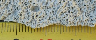
The last factor affects the heating surface area. Its influence can be seen on Soviet-era radiators. Their shape is such that only 0.23 m² of heat is transferred in one section.
Modern cast iron heating radiators have greater heat output. This is due to the different shape of the sections. For example, the modern heating device 1K60P-500 has half the weight of the M-140, as well as sections with a smaller heating area. It is 0.116 m². Power is measured at 70 watts. However, the heat transfer is greater because the shape of each section fin resembles a long, wide rectangle. With its wider side it “looks” into the room and at the adjacent wall. Thanks to this feature, the battery turns into a heating panel capable of producing a wide flow of heat. Finned batteries do not have this capability.
Calculation of heating radiators by area
The easiest way. Calculate the amount of heat required for heating, based on the area of the room in which the radiators will be installed. You know the area of each room, and the heat requirement can be determined according to SNiP building codes:
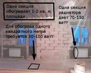
- for the average climate zone, 60-100 W are required for heating 1 m 2 of living space;
- for areas above 60 o, 150-200 W are required.
Based on these standards, you can calculate how much heat your room will require. If the apartment/house is located in the middle climate zone, heating an area of 16 m 2 will require 1600 W of heat (16*100=1600). Since the standards are average, and the weather is not constant, we believe that 100W is required. Although, if you live in the south of the middle climate zone and your winters are mild, count 60W.
Heat transfer calculation
It will be carried out on the basis of the M-140-AO model. It has the following parameters:
- The heat output determined by the manufacturer is 175 W/m².
- Heating area – 0.299 m².
The formula for calculating heat transfer is:
Q = K x F x Δ t, where
K – heat transfer coefficient,
F – heating surface area,
Δ t – temperature difference (measured in °C).
The formula for determining the temperature difference is:
Δ t = 0.5 x ((tin. + tout.) – tin.), where
tin. – coolant temperature at the inlet,
tout. – temperature of the coolant at the outlet,
tvn. – desired room air temperature.
In the example, it will be taken into account that a conventional boiler supplies water at a temperature of less than 90 °C. Let the coolant be heated to a temperature of 70 °C, and its outlet temperature will be 50 °C. The room temperature should be 21 °C.
In this case, Δ t = 0.5 x ((70 + 50) – 21) = 49.5. Rounded, Δt will be 50 °C. Next, you need to look at a special table that shows the values of the thermal pressure and the corresponding heat transfer coefficients.
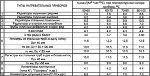
In it, the thermal pressure and heat transfer coefficient of high radiators are related as follows:
- 50-60 °C – 7.0.
- 60-70 °C – 7.5.
- 70-80 °C – 8.0.
- 80-100 °C – 8.5.
Looking at these ratios, it is clear that K = 7.0.
As a result, the total heat transfer of the section will be as follows:
Q = 7.0 x 0.299 x 50 = 104.65 W.
Heat transfer is always indicated with a 30% margin. Therefore, the resulting figure should be multiplied by 1.3.
The final heat transfer will be 104.65 x 1.3 = 136.05 W/m². The final result is not similar to the figure declared by the manufacturer due to the supply of colder coolant. Therefore, you need to determine the operating parameters of your heating system.
When selecting a cast iron radiator, you need to start from Δ t. The smaller it is, the larger the heating area the battery should have.
If this indicator is 60, then the size of the device should be 0.5 x 0.52 m. If it becomes half the size, then the height and width of the battery should be 0.5 and 1.32 m, respectively.
Heat dissipation of batteries made of different materials
When choosing a heating radiator, you should remember that they differ in the level of heat transfer.
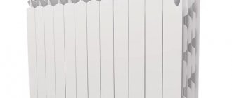
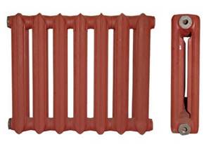
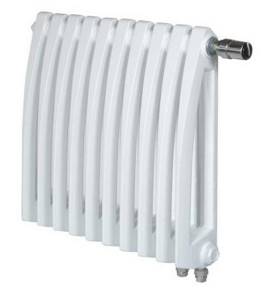
The purchase of batteries for a house or apartment should be preceded by a careful study of the characteristics of each model. Often devices that are similar in shape and size have different heat output. Cast iron radiators
. These products have a small heat transfer surface and are characterized by insignificant thermal conductivity of the manufacturing material. The rated power of a section of a cast iron radiator, such as MS-140, at a coolant temperature of 90°C is approximately 180 W, but these figures were obtained in laboratory conditions (for more details: “What is the thermal power of cast iron heating radiators”). Heat transfer is mainly carried out due to radiation, and convection accounts for only 20%.
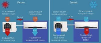
In centralized heating systems, the coolant temperature usually does not exceed 80 degrees, and in addition, part of the heat is consumed when hot water moves to the battery. As a result, the temperature on the surface of the cast iron radiator is about 60°C, and the heat transfer of each section is no more than 50-60 W.
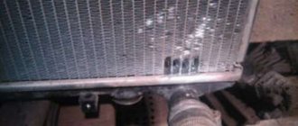
Steel radiators
. They combine the positive characteristics of sectional and convection devices. They consist, as can be seen in the photo, of one or several panels in which the coolant moves inside. To increase the heat transfer of steel panel radiators, special fins are welded to the panels to increase power, functioning as a convector.
Unfortunately, the heat transfer of steel radiators is not very different from the heat transfer of cast iron radiators. Therefore, their advantage lies only in relatively light weight and more attractive appearance.
Consumers should be aware that the heat transfer of steel heating radiators is significantly reduced if the coolant temperature decreases.
For this reason, if water heated to 60-70°C circulates in the heating system, the indicators of this parameter may differ greatly from the data provided for this model by the manufacturer. Aluminum radiators
. Their heat transfer is much higher than that of steel and cast iron products. One section has a thermal power of up to 200 W, but these batteries have a feature that limits their use. It serves as a coolant. The fact is that when contaminated water is used from the inside, the surface of the aluminum radiator is subject to corrosive processes. Therefore, even with excellent power indicators, batteries made of this material should be installed in private households where an individual heating system is used.
Bimetallic radiators
. These products are in no way inferior to aluminum devices in terms of heat transfer. The heat flow of bimetallic products is on average 200 W, but they are not so demanding on the quality of the coolant. True, their high price does not allow many consumers to install these devices.
Additional factors affecting heat transfer
This indicator is also affected by:
- Connection type.
- Features of accommodation.
The radiator can be connected in the following ways:
- Lateral.
- Diagonal.
- Nizhny.
Diagonal connection is the most effective. It consists of connecting the inlet pipe to the pipe located at the top of the heating device, and connecting the outlet pipe to the pipe located at the bottom of the opposite end. Thanks to this, the coolant can easily fill all sections and transfer heat to every particle of the heating radiator. In this case, it is not necessary to create very high pressure to move water or other heated liquid.
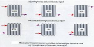
Lateral connection involves connecting pipes to the same section. The inlet pipe is located at the top, the outlet pipe at the bottom. This leads to poor heating of the last ribs. According to statistics, heat loss is 7%.
The lower connection diagram results in 20% losses. Heat transfer losses in the last two connection schemes to a heating device can be minimized by using forced circulation of heated liquid. A little pressure is enough to completely warm up all sections.
Battery placement is very important. If it is installed crookedly, air pockets will form in some sections. Heat transfer will be less.
The loss of heat transfer can be like this:
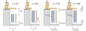
- 7-10% – if the permissible distance between the device and the window sill is exceeded. It should be 10-15 cm;
- 5% – in case of decreasing the distance between the wall and the battery. The optimal size is 3-5 cm;
- 7% – in a situation where the distance between the floor and the radiator is not maintained. It should be 10-15 cm.
How to calculate radiator sections by room volume
This calculation takes into account not only the area, but also the height of the ceilings, because all the air in the room needs to be heated. So this approach is justified. And in this case the technique is similar. We determine the volume of the room, and then, according to the standards, we find out how much heat is needed to heat it:
- in a panel house, heating a cubic meter of air requires 41 W;
- in a brick house per m 3 - 34 W.
You need to heat the entire volume of air in the room, so it is more correct to calculate the number of radiators by volume
Let's calculate everything for the same room with an area of 16m2 and compare the results. Let the ceiling height be 2.7m. Volume: 16*2.7=43.2m3.
Next we will calculate for options in a panel and brick house:
- In a panel house. The heat required for heating is 43.2m 3 *41V=1771.2W. If we take all the same sections with a power of 170 W, we get: 1771 W/170 W = 10,418 pcs (11 pcs).
- In a brick house. The heat needed is 43.2m 3 *34W=1468.8W. We count the radiators: 1468.8W/170W=8.64pcs (9pcs).
As you can see, the difference is quite large: 11 pieces and 9 pieces. Moreover, when calculating by area, we got the average value (if rounded in the same direction) - 10 pcs.
Dependence of radiator power on connection and location
In addition to all the parameters described above, the heat transfer of the radiator varies depending on the type of connection. A diagonal connection with a supply from above is considered optimal; in this case, there is no loss of thermal power. The largest losses are observed with lateral connections - 22%. All others are average in efficiency. Approximate percentage losses are shown in the figure.
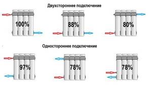
Heat loss on radiators depending on connection
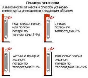
The actual power of the radiator also decreases in the presence of obstructing elements. For example, if a window sill hangs from above, the heat transfer drops by 7-8%; if it does not completely block the radiator, then the loss is 3-5%. When installing a mesh screen that does not reach the floor, the losses are approximately the same as in the case of an overhanging window sill: 7-8%. But if the screen completely covers the entire heating device, its heat transfer is reduced by 20-25%.
The amount of heat depends on the installation
The amount of heat depends on the installation location
What needs to be taken into account when calculating?
Calculation of heating radiators
Be sure to take into account:
- The material from which the heating battery is made.
- Its dimensions.
- The number of windows and doors in the room.
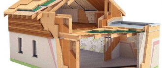
- The material from which the house is built.
- The direction of the world in which the apartment or room is located.
- Availability of thermal insulation of the building.
- Type of pipe system layout.
And this is only a small part of what needs to be taken into account when calculating the power of a heating radiator. Don’t forget about the regional location of the house, as well as the average street temperature.
There are two ways to calculate the heat transfer of a radiator:
- Regular - using paper, pen and calculator. The calculation formula is known, and it uses the main indicators - the thermal output of one section and the area of the heated room. Coefficients are also added - decreasing and increasing, which depend on the previously described criteria.
- Using an online calculator. It is an easy-to-use computer program into which certain data about the size and design of the house is loaded. It gives a fairly accurate indicator, which is taken as the basis for designing a heating system.
For the common man, both options are not the easiest way to determine the heat transfer of a heating battery. But there is another method for which a simple formula is used - 1 kW per 10 m² of area. That is, to heat a room of 10 square meters, you will need only 1 kilowatt of thermal energy. Knowing the heat transfer rate of one section of a heating radiator, you can accurately calculate how many sections need to be installed in a particular room.
Let's look at a few examples of how to correctly carry out this calculation. Different types of radiators have a large size range, depending on the center distance. This is the size between the axes of the lower and upper manifold. For the bulk of heating batteries, this figure is either 350 mm or 500 mm. There are other parameters, but these are more common than others.
This is the first one. Secondly, there are several types of heating devices made of various metals on the market. Each metal has its own heat transfer, and this will have to be taken into account when calculating. By the way, everyone decides for themselves which radiator to choose and install in their home.
Calculation of thermal elongation of pipelines made of cross-linked polyethylene PE-Xa
Temperature extensions or shortenings of pipelines occur due to changes in the operating temperature of the water circulating through them, as well as the ambient temperature. When laid open, the pipeline must be free to lengthen or shorten without overstressing the material of the pipes, fittings and connections of the pipeline. This is achieved due to the compensating ability of the pipeline elements. For example:
- Correct placement of supports (mounts).
- The presence of bends in the pipeline at turning points, other bent elements and the installation of temperature compensators.
The installation of compensators is necessary only for significant linear extensions of pipelines . Since the system must be rational, the thermal elongation of the pipeline is first calculated. Let's take pipelines made of cross-linked polyethylene RE-Xa. To calculate we need:
Tab. 1. Thermal expansion coefficient and material constant for water pipes.
| Pipe type | Pipe diameter | Thermal elongation coefficient α mm/m K | Material constant C |
| Universal pipe made of cross-linked polyethylene PE-Ha | 16-63 mm Without fixing channel | 0.15 | 12 |
| Water pipe made of cross-linked polyethylene RE-Ha | 16-63 mm Without fixing channel | 0.15 | 12 |
Sergei Bulkin
Thermal elongation of a pipeline section is proportional to its length and the difference in installation temperatures and maximum operating temperature. If, for example, we are installing a section of a hot water pipeline 10 m long, and the ambient temperature, i.e. installation temperature is 20°C, and the maximum operating temperature is 70°C, then the thermal elongation can be calculated using the formula
ΔL = L • α • ΔT (t max. operation – t installation). Where:
- ΔL—temperature elongation in mm;
- L—pipeline length in m;
- α is the coefficient of thermal expansion in mm/m K;
- ΔT is the temperature difference in K.
Substitute the values into the formula:
ΔL = L • α • (t max. work. – t installation) = 10 • 0.15 • (70 – 20) = 75 mm.
Those. In this case, the 10-meter section will lengthen by 75 mm or 7.5 cm. This will lead to deformation of the system and sagging of the pipeline. These deformations, first of all, disrupt the appearance of the system. But over a significant length they can destroy, first of all, fastening devices or lead to breakage of shut-off and control valves or fittings. The human eye is capable of perceiving pipeline deflection (ΔН) starting from 5 mm .
Pipe deflection as a result of thermal expansion.
The next step is to calculate the amount of deflection (sagging) of the pipeline.
Polymer pipelines for modern open plumbing and heating installations
Modern metal-polymer pipelines are a cross-linked polyethylene pipe in which a layer of aluminum is firmly glued to an internal self-supporting layer of PE-Xa. Such pipelines have the lowest coefficient of thermal expansion, because the aluminum layer compensates for thermal expansion and keeps the inner polymer layer from thermal deformation.
The coefficient of thermal expansion of metal-polymer pipelines is only 0.026 mm/m K, which is 5.76 times less than that of conventional pipelines made of cross-linked polyethylene.
The thermal elongation of a section of a metal-polymer pipeline 10 m long at ambient temperature (i.e. installation temperature 20 °C and maximum operating temperature 70 °C) will be only:
ΔL = L • α • (t max. work. – t installation) = 10 • 0.026 • (70 – 20) = 13 mm.
For comparison: we previously calculated the thermal elongation of a conventional PE-Xa pipeline 10 m long, which amounted to 75 mm.
Therefore, metal-polymer pipelines are positioned as pipelines for open installation. But the option with metal-polymer pipes will be more expensive, because... these pipes cost more than conventional PE-Xa cross-linked polyethylene pipes.
Methods for compensating for temperature deformations of polymer pipelines
1. Installation of additional fastening clamps.
By installing additional fastening clamps, sagging or deflection of pipelines is prevented. The recommended maximum distance between clamps for polymer pipes made of PE-Xa is given in Table 2.
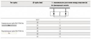
Recommended maximum distance between fastening clamps when laying pipes made of cross-linked polyethylene PE-Xa for various diameters.
2. L-shaped compensator device.
L-shaped compensators are arranged in the same way as when laying steel pipelines. It is much more efficient to install L-shaped expansion joints on polymer pipes made of PE-Xa, because These pipes are highly elastic. At the same time, places where pipelines turn at 90° can be used as L-shaped compensators. It is necessary to use the formula, as described above, to determine the temperature elongation ΔL from the straight section before the turn. This value affects the distance from the pipeline to the building structure. The distance to the building structure must be at least ΔL. In addition, it is necessary to allow the pipe to bend freely. To do this, the first fastening clamp, after turning, should be installed at a certain distance from the turn.
This distance is called the compensator arm length and is designated LBS.
Construction of an L-shaped compensator on polymer pipes.
Where:
- LBS – compensator arm length;
- x – minimum distance from the wall;
- ΔL – temperature elongation;
- FP – fixed support;
- L – pipe length;
- GS – sliding clamp.
The length of the compensator arm mainly depends on the material (material constant C). Compensators are usually installed in places where the direction of the pipeline changes.
Fixing gutters are not installed on compensators so as not to disturb the bend of the pipe.
The length of the compensator arm is determined by the formula:
Where:
- C – pipe material constant;
- d – outer diameter of the pipeline in mm;
- ΔL – thermal elongation of the pipeline section.
If the thermal elongation is 75 mm, the material constant C = 12, and the pipeline diameter is 25 mm, then the length of the compensator arm will be:
This means that the first sliding clamp should be installed at a distance of 519 mm from the turning point.
Sergei Bulkin
The L-shaped compensator is the most economical device for compensating for thermal expansion. Its device does not require any additional devices or elements.
3. U-shaped compensator device.
U-shaped compensators are installed in cases where compensation of thermal expansion at the edges of the site is undesirable. It is installed, as a rule, in the middle of the pipeline section, and compensation for temperature expansion is directed towards the center of the section. The bases of the U-shaped compensator are shifted towards the center evenly on both sides, so each side compensates for half of the thermal expansion ΔL/2. The arms of the U-shaped compensator are the LBS compensation arms.
The length of the compensator arm is calculated using the above formula, and the width of the base of the U-shaped compensator must be at least half the length of the compensator arm.
Construction of a U-shaped compensator on polymer pipes.
4. Fixing groove as a compensator for thermal expansion.
The fixing gutter is a three-meter-long galvanized steel tray with flanging along the edges. Fixing gutters are produced for the corresponding diameters of pipelines. The pipelines are snapped into the fixing grooves. In this case, the fixing groove covers the pipe approximately 60°.
The frictional forces of the pipeline against the walls of the gutter exceed the force of thermal expansion of the pipeline.
When installing the fixing channel, it is necessary to maintain a distance of 2 mm from the polymer slide sleeves.
Sergei Bulkin
The coefficient of thermal elongation of a cross-linked polyethylene pipe (α) in a fixing trench with a diameter of 16 to 40 mm is 0.04 mm/m K, which is 3.75 times less than that of conventional PE-Xa pipes.
The fixing groove is easily cut with a hacksaw or cut with a grinder. In this case, you should cut along the semicircular part so as not to bend the edges. The cut edge should be deburred. A short piece of the fixing gutter is placed at the junction of the fixing gutters.
When installing a fixing trench at the bottom of the pipeline, its mechanical protection is ensured.
When using a fixing chute, the minimum distance between the fastening clamps when using pipelines of all diameters can be 2 m.
5. Using fixed supports
If it is necessary to compensate for temperature elongations on a long section of a pipeline on which there are many branches, for example, a water riser in a 20-story building, on each floor of which tees for apartment wiring are installed, then compensation for temperature elongations can be done by installing fixed supports. To do this, conventional sliding clamps are installed on both sides of the tee behind the sliding sleeves.
Formation of a fixed support as a compensator for thermal expansion of the pipeline.
The clamps will not allow the shaped part to move either up or down. Thus, the long section is divided into many short sections equal to the floor height, approximately 3 m. As we remember from the calculation formula, thermal elongation is directly proportional to the length of the section, and we have reduced it. When installing fixed supports on each floor on the riser, no other compensators for thermal expansion of the pipeline will be required. If there is, for example, a “idle” riser, which does not have side branches along its entire length, then you can artificially install, for example, equal couplings on this riser and form fixed supports on them, as described above. To reduce costs, you can install L or U-shaped expansion joints on the riser or install a bellows expansion joint.