Automation of production, technological processes, operation of household and other appliances is often associated with monitoring temperature changes; high-precision sensors with low inertia - thermocouples (TC) are used there. Differences from other temperature meters, for example, from thermistors: the principle is based on the generation of current when the soldered electrodes are heated, the temperature range is much wider. There are also disadvantages: the need for amplifiers, converters, sometimes certain conditions are needed to reduce errors. With a multimeter, the TP is used to study the heating of electronics and other objects. Let's consider what a thermocouple is, advantages and disadvantages, features, types. We will describe where thermoelectric converters are more appropriate and how to assemble them yourself.

Thermocouple concept
Thermocouples (thermoelectric converters, TC) are sensors for measuring t°, based on the principle of transforming heat into electrical processes.
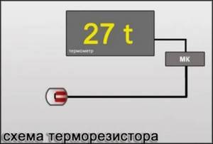
The thermoelectric converter itself does not process the readings, but transmits them to a separate unit for this purpose, to the application chip (serviced or special measuring equipment).
The thermal converter sensor has sufficient accuracy and low inertia. The operating temperature range is wider than that of thermistor sensors, as well as better resistance to mechanical and other loads (these are the main advantages).
Folk crafts
Many craftsmen, using a thermoelectric converter, make chargers or miniature power stations at home for charging phones and other low-power devices. Moreover, this comes from fire or any other hot source.
Some people try to make a thermocouple with their own hands based on an already faulty device. Only such homemade products cannot be used for a long time. But they are suitable as a temporary replacement.
Where are thermocouples used?
TP is more often used than other sensors for equipment associated with high positive temperatures: fuel boilers and stoves, other equipment with burners, boilers, soldering irons, pyrometers, furnaces, metallurgy.
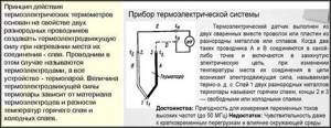
The term "thermoelectric converter" reflects the nature of the sensor - a differential meter that makes measurements by converting heat into electricity.
Thermocouples are simple and effective sensors for high-precision thermoelectric thermometers operating at elevated temperatures.
A striking example of application: in automatic components for fuel boilers and heating. The activation of the equipment is initiated by an electrical signal from the sensor node with the TP.
Thermocouples, along with NTC and PTC thermistors, are the most popular temperature meters for equipment; the latter have their advantages (they are considered more accurate in their ranges), but do not cover such a wide temperature range as TCs.
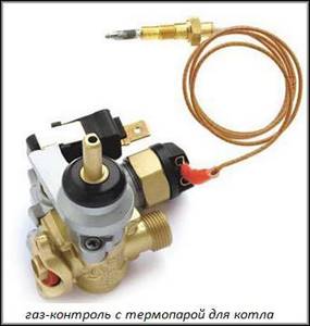
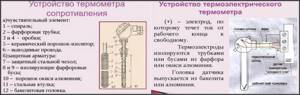
Why is a thermocouple needed in a gas boiler?
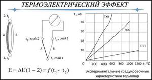
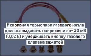
A thermocouple (also known as a thermoelectric thermometer) is a control and measuring module that, when heated, produces a low voltage, which is sufficient to hold the gas supply solenoid valve in the open position. In fact, a thermocouple is needed solely for safety reasons: as soon as for some reason (for example, due to reverse draft) combustion stops in the combustion chamber of the boiler, the thermocouple will not be able to keep the gas supply valve open, the fuel supply will stop, gas leaks into the premises will be prevented.
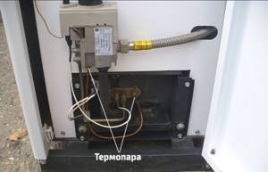
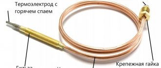
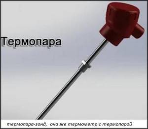
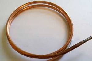
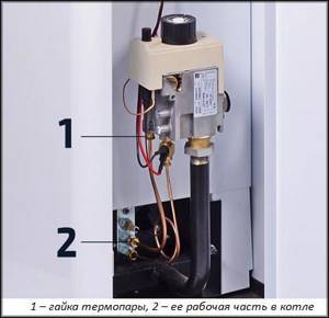
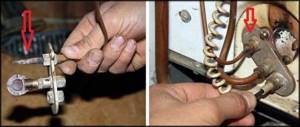
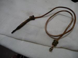
The photo shows the standard location of the thermocouple in a gas boiler. It can be identified by its copper tube.
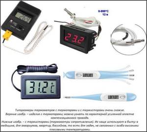
In addition to gas boilers, thermoelectric sensors are used in household gas stoves, stoves, and water heaters. Therefore, when choosing, it is necessary to select a thermocouple specifically for gas boilers, or more precisely for a specific model of boiler unit or automation (usually the Italian automatic EuroSit 630 and its analogues).
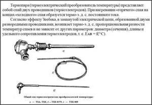
What is a thermocouple and its device
TP is regulated by GOST 6616, R 8.585 and IEC 62460, 60584. Clause 2.2 of the latter defines a sensor: a pair of different alloy conductors with a connection (solder) at one end to initiate a thermoelectric effect for measuring t° with this segment. TP measures the connection point (head) of its electrodes, the so-called “hot junction”.
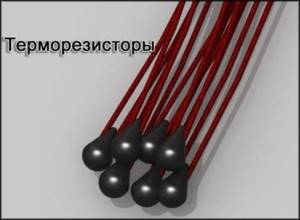
You need to understand that the thermocouple device may consist of unsightly pieces of thin wires soldered at one end, but despite this, the sensor is extremely effective. Often contains precious metals.
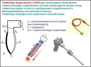
Device:
- two conductors, soldered at one end, less often twisted. This is the hot junction, the sensitive segment that takes measurements;
- the other ends are a place where there is no heating, connections to extension wires, a cold junction. They are connected to the indicator receiver.
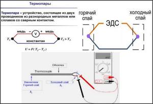
A closed circuit is created; if a galvanometer, microvoltmeter, or multimeter is connected to its break, they will show the thermoEMF of several milli- or microvolts that has arisen there. The value depends on the degree of heating at the wire connection and on the temperature indicator in the segment where there is none.
That is, the magnitude of the EMF depends on the difference in t° between the cold and hot junctions and on the thermoelectric properties of the alloys of the conductors themselves.
If the hot point of the connection is heated, then a potential difference will appear between their unconnected (cold) ends.
Next, a separate converter or on the control unit of the device being serviced calculates the temperature, since the strength of the EMF and it are interdependent, then converts the received data into numbers and/or into commands for control.
What is KHS
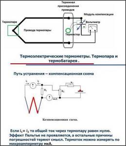
For particularly accurate measurements, the temperature in the cold segment must remain constant, but this is difficult to achieve under normal conditions, so special compensation circuits are used. The voltage recorded at the specified section of the TP depends on the difference in t° on it and on the hot segment. Therefore, you need to know the heating level of the first to calculate that of the second. Such calculations are called cold junction compensation - CJC and it is often used for emergency shutdowns or to control other pulse generation units.
They always strive to measure (calculate) CHS closer to the point of intended measurements with a thermocouple, since extended wires are sensitive to electrical interference (the signal deteriorates). This circumstance is significant for manufacturers when designing temperature sensors.
Operating principle
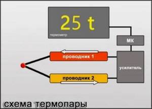
In short, the TC consists of wires made of 2 different alloys with their own electrical characteristics under thermal influences: a certain potential difference and a weak current are created, which is recorded by the receiver of such readings.
But if you delve deeper into the study of a thermocouple, then you need to talk about significant special nuances of how it works.
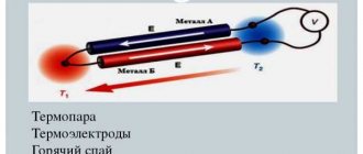
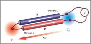
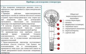
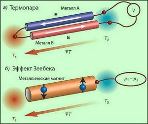
The operating principle of a thermocouple uses thermoelectric response, first described by the scientist T. Seebeck. The connected conductors have a contact potential difference. Structurally, the sensor consists of 2 cores made of different alloys.
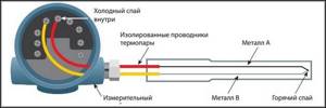
The ends form a head - a contact, the so-called hot junction (red in the diagram below), created by twisting, and more often by welding (seam, butt). The free ends go to the processing data, control units of the equipment being serviced, they are closed by compensation wires to the contacts of such devices, and at the connection points with the TP there is a cold junction (blue in the figure below).
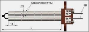
Electrodes made of different metals, conventionally A and B, are also shown in different shades in the drawing above. They are protected by a sealed capsule (may contain an inert gas or liquid), ceramic cylinders (shown in the image below).
Explanation from Wikipedia:
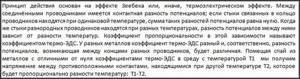
The action is based on an effect with thermoelectric properties (named after the scientist T. Seebeck). If the circuit is closed, for example, with a millivoltmeter, thermo-EMF (electromotive force) appears at the junction points. If we used electrodes from the same alloys, then they would heat up equally (equivalently), the EMF would be mutually compensated, and no current would arise.
A thermocouple, how it works, what it is in simple terms: different conductors heat up differently, their junctions have non-identical temperatures, so a potential difference arises between them, initiating a thermo-EMF, which maintains a weak current in such a circuit. The value is proportional to the difference in t° of the junctions. It must be emphasized that it is this that needs to be taken into account, and not other indicators.
Another simple explanation of how a thermocouple works: if you connect 2 different metal conductors, creating a closed electrical circuit, and heat the point of this connection, an electromotive force (thermoEMF) and a small electric current will appear. The TP transmits this data to the microcircuit of the serviced or measuring device, which processes it, calculating t°.
Features, nuances of accuracy
The voltage at the cold tips is proportionally dependent on t° in the area of the hot junction. In a certain temperature range, a linear thermoelectric property is observed, showing the dependence of the voltage on the level of difference t° between the points of the warm and cold element of the TC. Linearity is conditional - we can talk about it only when t° at the latter is constant. This nuance must be taken into account if calibration is being done: when changing the heating at the cold ends, there is a possibility of a significant error
When high measurement accuracy is required, the cold ends are placed in special capsules, where the stability of one selected temperature level is maintained by special electronic devices that process the resistance thermometer readings. With this approach, accuracy up to ±0.01 is achieved. But this is required only for a few technological processes. In most cases, for example, when operating thermocouples in refrigerators, water heaters and other household appliances, the requirements are less stringent and allow deviations an order of magnitude lower.
Flaws
Unfortunately, such simple devices, along with obvious advantages, also have some disadvantages. First of all, it is worth mentioning the error, which is usually 0.5-2 degrees. Therefore, in order to achieve more accurate readings (up to ±0.01 °C), individual calibration of the thermocouple is necessary.
Simplicity of design and high reliability, while being an invaluable advantage, are also a minus. How can this be? Everything is very simple - if a thermocouple malfunctions, there is no way to repair it, only replace it.
Fortunately, this disadvantage of thermocouples for plates is not so significant, since the cost is not so high.
Differences between thermocouples and thermistors (NTC PTC)
Differences between thermoelectric converters and thermistors (resistance sensors):
- principle of operation. A small current appears on the thermocouple, changing with different heating of its head, and the thermistor (semiconductor) reacts to such processes by changing its resistance;
- constructive. Thermocouple design: two soldered conductors (the current flows from them) made of different alloys in a protective casing and with compensation wires, the thermistor is a solid piece of semiconductor with conductors (the current flows to it), the resistance of which is sensitive to temperature.
The thermocouple has the following advantages:
- operating range t° is much higher: the typical one reaches +600...+800° C, thermistors have a standard maximum positive limit of about +200...+600° C. There are thermocouples made of special alloys that operate at +2500° C, which cannot be called anything for them - outstanding, these are, in general, ordinary parameters. But thermal sensors also have special families of high-temperature models. But these are more special devices, and yet their range is smaller;
- thermistors are more accurate, but with some caveats. At high temperatures, errors, as well as degradation, their calibration may be higher than that of TP. That is, at particularly high temperatures, thermocouples can be more accurate. This minus for them is also leveled out if there is a converter that calculates errors;
- often a normalizing amplifier is required, which is needed for a thermocouple, to increase sensitivity so that its signal is stronger for better operation of the receiver processing the information so that it “sees” it;
- The thermistor is cheap due to the fact that it does not require the specified additional components. For TP such devices are often required, so in the end the cost of their use is higher;
- resistance to mechanical influences and vibrations of thermocouples is better, they have reliable protective covers;
- the reaction speed of TCs is higher than that of thermistors;
- When working at elevated temperatures, thermistors are more susceptible to wear and miscalibration. But this minus is relative - such a sensor is often simply thrown away and a new one is bought, since the product is cheap;
- Thermistors degrade faster over time. Manufacturers usually provide a warranty of only 1000 hours for such detectors. Thermocouples are more durable.
So, measuring temperature with a thermistor and a thermocouple differs fundamentally, although in both cases it is based on electrical parameters: the second creates and changes the EMF, the first - its resistance.
There is a rule: if the temperature is above +300° C, then a thermocouple should be used. Thermistors are more common on simpler and cheaper devices. Expensive and complex equipment uses thermocouples, which are also more common when working with high temperatures. Thermistors under such conditions may have the same errors as TCs, but in typical ranges (−50...+300° C) they have superior accuracy.
If we talk about special narrowly focused areas - laboratories, special research, industry - then TP is more often used there.
Let's summarize:
- advantages of a thermocouple: the operating temperature range is much wider, the response is faster, the service life is much longer than that of thermistors, TCs are less susceptible to miscalibration, degradation, and mechanical damage. In the temperature range from +300° C, thermocouples are often irreplaceable;
- disadvantages: the peculiarities of using TCs increase costs (partially offset by survivability), and it is also generally accepted that the accuracy of thermocouples is slightly worse than that of thermistors.
Let us separately highlight an absolute plus: only thermocouples are used as temperature meters of the objects under study (radio components, etc.) together with a multimeter. It must also be said that unsuitable t° ranges always increase errors and the likelihood of failure, but the TP is resistant to such conditions.

Pros and cons of the device
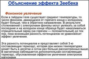
The thermocouple is the oldest and still the most common temperature sensor in the industry. The operation of a thermocouple is based on an effect that was first discovered and described by Thomas Seebeck in 1821 - the occurrence of current in a closed circuit of two dissimilar conductors in the presence of a temperature gradient between the junctions.
Since the generation of thermo-EMF occurs along the length of the thermoelectrode, the thermocouple readings depend on the state of the thermoelectrodes in the zone of maximum temperature gradient. Therefore, verification of thermocouples should be carried out at the same depth of immersion in the medium as at the work site. Taking into account thermoelectric inhomogeneity is especially important for working thermocouples made of base metals.
Pros and cons of thermocouple
Wide operating temperature range, they are the highest temperature contact sensors available.
The thermocouple junction can be directly grounded or brought into direct contact with the object being measured.
Ease of manufacture, reliability and structural strength.
The need to control the temperature of the cold junctions.
Over long lengths of thermocouple and extension wires, an “antenna” effect may occur to existing electromagnetic fields.
The dependence of Thermo-EMF on temperature is significantly non-linear. This creates difficulties when developing secondary signal converters.
Modern thermocouple-based meter designs use the measurement of the cold junction block temperature using a built-in thermistor or semiconductor sensor and automatically apply a correction to the measured Thermo-EMF. The occurrence of thermoelectric inhomogeneity in conductors and, as a consequence, a change in the calibration characteristic due to changes in the composition of the alloy as a result of corrosion and other chemical processes.
It will be interesting➡ What is electric power and how to calculate it
The electrode material is not chemically inert and, if the thermocouple body is not tightly sealed, it may be exposed to aggressive environments, atmosphere, etc. When stringent requirements are placed on the thermal inertia of the thermocouple and the operating junction must be grounded, the signal converter must be electrically isolated to eliminate the risk of ground leaks.
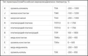
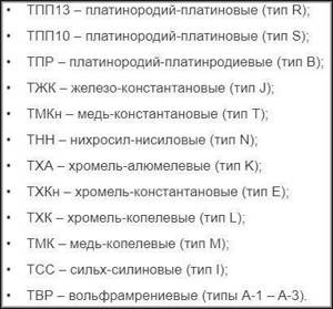
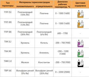
Depending on the materials of thermoelectrodes, thermocouples made of noble and base metals are distinguished. The first include platinum group thermal converters (TPP, TPR). The ignoble ones include TVR, THA, TKhK, TMK, TNN, TZhK and others from mass-produced ones.
Types of thermoelectric type converters
The types of thermocouples are extremely extensive. There are two main separation factors: by type of alloy and by soldering option. Multipoint transformer stations are also a separate type.
Type of electric couples depending on conductor alloys
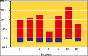
A thermocouple creates an EMF, the principle is always the same, but the alloys heat up differently, so the operating ranges, response speed, and errors may fluctuate.
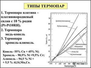
Different combinations of metals have their own parameters that determine the output voltage pulse, but the main thing is the temperature range in which one or another type of sensor can be used
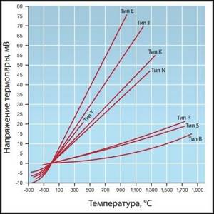
As the output voltage amplitude increases, the measurement resolution improves. Repeatability increases and, accordingly, accuracy increases.
There are different ratios of resolution and t° range for specific types of TC, which makes them suitable for certain conditions.
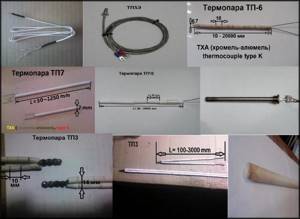
There are 9 types of thermocouples based on the composition of the conductor alloys:
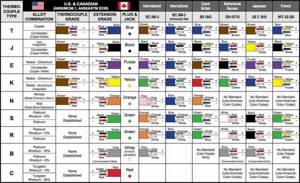
Varieties are designated by letters. (J, K, T, E, N, R, S, B, C).
The thermocouple type K (another designation is TXA) is important for us: it is the most common, suitable for use in household and other devices and for tasks that do not have any special requirements.
Traditionally, TXA is always recommended unless there is justification for using other types. Below is a description of a type K thermocouple from a highly specialized electronics site:
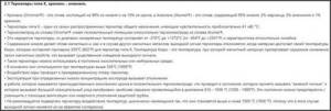
Features of the use of the most common thermocouples
Technical characteristics depend directly on the materials from which they are made.
Type J (Iron Constantan Thermocouple)
- It is not recommended to use below 0°C, because Moisture condensation on the iron terminal leads to the formation of rust.
- The most suitable type for rarefied atmospheres.
- The maximum temperature of use is 500°C, because Above this temperature, rapid oxidation of the leads occurs. Both terminals are quickly destroyed in a sulfur atmosphere.
- The readings increase after thermal aging.
- Low cost is also an advantage.
Type E (chromel-constantan thermocouple)
- The advantage is high sensitivity.
- Thermoelectric homogeneity of electrode materials.
- Suitable for use at low temperatures.
Type T (copper-constantan thermocouple)
- Can be used below 0°C.
- Can be used in atmospheres with slight excess or deficiency of oxygen.
- Use at temperatures above 400°C is not recommended.
- Not sensitive to high humidity.
- Both leads can be annealed to remove materials causing thermoelectric inhomogeneity.
Type K (chromel-alumel thermocouple)
- Widely used in various areas from -100°C to +1000°C (recommended limit depending on the diameter of the thermoelectrode).
- In the range from 200 to 500°C, a hysteresis effect occurs, i.e., readings during heating and cooling may differ. Sometimes the difference reaches 5°C.
- Used in a neutral atmosphere or an atmosphere with excess oxygen.
- After thermal aging, the readings decrease.
- It is not recommended to use in a rarefied atmosphere, because... chromium can be released from the Ni-Cr terminal (so-called migration), and the thermocouple changes the thermoelectric force and shows a low temperature.
- A sulfur atmosphere is harmful to a thermocouple because affects both electrodes.
Type K thermocouple.
Type N (nicrosil-nisil thermocouple)
- This is a relatively new type of thermocouple, developed from the K-type thermocouple. The K-type thermocouple can be easily contaminated by impurities at high temperatures. By fusing both electrodes with silicon, the thermocouple can be precontaminated and thus reduce the risk of further contamination during operation.
- Recommended operating temperature up to 1200°C (depending on wire diameter).
- Short-term operation is possible at 1250°C.
- High stability at temperatures from 200 to 500°C (significantly less hysteresis than for a type K thermocouple).
- Considered to be the most accurate base metal thermocouple.
General Tips for Selecting Base Metal Thermocouples
- Application temperature below zero – type E, T
- Room temperatures for use – type K, E, T
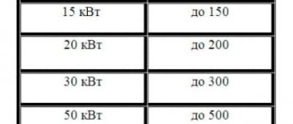
- Application temperature up to 300°C – type K
- Application temperature from 300 to 600°C – type N
- Application temperature above 600°C – type K or N
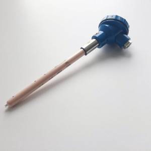
Precious metal thermocouples
- Recommended maximum operating temperature 1350°C.
- Short-term use is possible at 1600°C.
- It becomes contaminated at temperatures above 900°C with hydrogen, carbon, and metallic impurities of copper and iron. When the iron content in the platinum electrode is 0.1%, TEMF changes by more than 1 mV (100°C) at 1200°C and 1.5 mV (160°C) at 1600°C. The same picture is observed with copper contamination. Thus, thermocouples should not be reinforced with steel tube, or the electrodes should be insulated from the tube with gas-tight ceramics.
- Can be used in oxidizing atmosphere.
- At temperatures above 1000°C, the thermocouple may become contaminated with silicon, which is present in some types of protective ceramic materials. It is important to use ceramic tubes consisting of high purity aluminum oxide.
- It is not recommended to use below 400°C, since the thermoelectric force in this region is small and extremely nonlinear.
Precious metal thermocouples
Type R (platinum-rhodium-platinum)
The properties are the same as those of type S thermocouples.
It will be interesting➡ What is a Faraday cage
Type B (platinum-platinum-rhodium)
- Recommended maximum operating temperature is 1500°C (depending on wire diameter).
- Short-term use is possible up to 1750°C.
- Can become contaminated at temperatures above 900°C with hydrogen, silicon, copper and iron vapor, but the effect is less than for thermocouples of types S and R.
- At temperatures above 1000°C, the thermocouple may become contaminated with silicon, which is present in some types of protective ceramic materials. It is important to use ceramic tubes consisting of high purity aluminum oxide.
- Can be used in oxidizing environments.
- Application is not recommended at temperatures below 600°C, where the emf is very small and nonlinear.
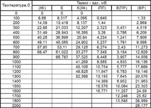
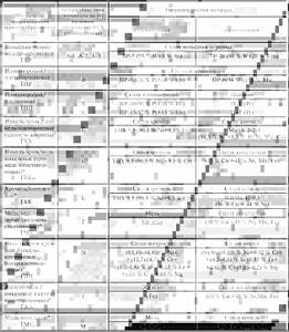
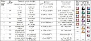
Summary table of thermocouple types.
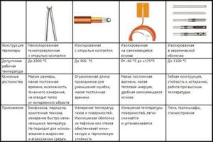
Junction options
Junctions are created with different specific configurations for specific purposes of thermocouples. There are 1 and 2-element options, with or without grounding to the body of the protective capsule.
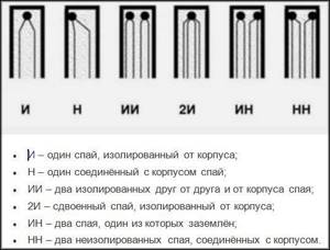
Grounding to the housing (not always present) reduces the inertia of the thermocouple, and this improves sensor performance and real-time accuracy. Also, to achieve better efficiency, some models have a hot junction outside the protective flask (casing, housing).
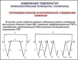
Multipoint thermoelectric converters
Sometimes it is necessary to measure t° at different points simultaneously. A multipoint thermocouple type solves this problem. Such sensors record data along the axis of the transducer. For standard, everyday tasks, such products are rare - they are used in the chemical and petrochemical industries, where it is necessary to study how the temperature is distributed in containers, reactors, etc. The number of points can reach 60. Such a thermocouple does not require complex maintenance; one capsule and one input are used into the installation.
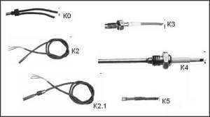
Other design options
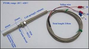
The different design solutions are shown below:
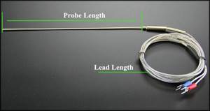
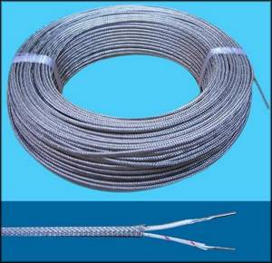
Below are several options for thermal converters with cable leads:
The role of extension (compensation) wires
An extension, also known as a compensation wire or cable for a thermocouple is needed so that it can connect to remote equipment chips, to a secondary or serviced device, a receiver that processes data, and also to study remote areas.
Any wires are not used for extension (we will indicate an exception below). This is another difference from thermistors. It is necessary to use the same material as in the thermocouple. For example, for a K-type sensor with chromel-alumel conductors, the same wiring marked XA is used.
The compensation cable can be omitted only when the TP has a converter that calculates and removes the error. The most common form of this is a “pill” inside the terminal segment of the detector with a 4-20 mA signal of a unified type.
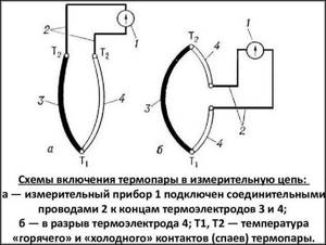
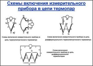
How thermoelectric converters are connected
At each new mark of the connection of different alloy cores, a cold junction is formed, and this, as we have already described, affects the correctness of the measurements. It is advisable to make the connection with wires similar in composition to the electrodes.
As a rule, manufacturers initially equip sensors with such compensation cables; they can also be purchased in specialty stores. But, as we noted above, this is not relevant if there is a normalizing converter, a correction circuit based on a thermistor. The TC wires are simply plugged into the sockets of such nodes according to polarity.
It is advisable to place the measuring systems closer when connecting the TP in order to reduce the cable length to the minimum possible. Any wire has a risk of interference, and the longer it is, the greater the deviation. If radio interference can be eliminated by shielding, interference is more difficult to level out.
The thermocouple connection circuit may include a compensation thermistor between the receiver contacts and the cold segment point. External t° affects these elements in a similar way, so such a part will correct errors:
Having connected the TP to the meter, it is necessary to perform calibration; there are special tables on the network.
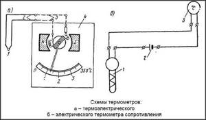
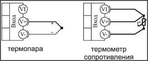
Designation of thermocouples in the diagrams:
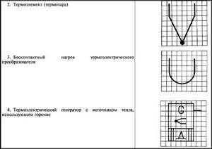
Designations from GOST standards:
Example:
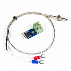
Making a thermocouple for a multimeter yourself
A thermocouple, created by yourself, is a sensor that is basically structurally similar to the factory one: two soldered electrodes of different composition.
List of materials, tools:
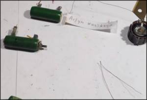
- Konstantin. Available in old Soviet low-resistance ceramic resistors PEV-10 or similar;
- wire, copper;
- lighters: turbo (“stove”) and regular.
The data receiver can be any digital or analog tester. Using such a TP for a multimeter, you can measure the temperature of the objects under study.
Where to get wire
The smaller the wire cross-section, the lower the TP errors, since the very influence of the core array on heat transfer is reduced.
In our example, 2 wires are taken from the following alloys:
- Constantine. We take it from an old ceramic resistor PEV-10. The alloy also contains the foreign analogue 1R00JSMT and similar types of radio components. Some of these radio components are made with nichrome - it will not work;
- copper wires: from the windings of used transformers from household appliances, from cables, for example, twisted pair.
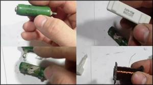
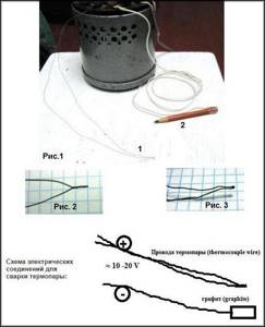
Twisting, welding
We make a twist of 2 wires. Then we weld this end: since the wires are thin, a turbo lighter, popularly known as a “stove,” will do. You should get a round droplet head. The remaining turns must then be untwisted so that there is no short circuit.
We have already described the principle of operation: when heated at the hot junction, that is, the droplet head, a potential difference arises, initiating a small current that will flow through the wiring to the receiver (multimeter). The values of such electricity will characterize a certain temperature.

Other welding methods
Wiring can also be soldered using handicraft welding, for example, using laboratory autotransformers or a car battery. To one pole (“+”) of such a source we connect both ends of the thermocouple, twisted or mechanically connected with wire. To the other we connect the terminal (“−”) connected to a piece of graphite. An electric arc will occur and welding will occur.
The voltage for welding is selected experimentally: they start with low values of 3–5 V and gradually increase to the desired result. The optimal value depends on the metal of the wire, its cross-section, length - it usually does not exceed 40–50 V. Be safe: do not touch bare areas, do not apply too much voltage. For convenience, dangerous segments are insulated with electrical tape, cambric, and ceramic tubes.
A good connection is obtained by heating the wiring with an arc discharge, igniting it between them and a strong (ropa) solution of table salt.
Other alloys for electrodes
Above we showed an example with constantine-copper electrodes. A thermocouple for measuring temperature with your own hands can also be created using wire from other materials (see table above for alloys). Such materials are sold on highly specialized trading platforms, but they are still more difficult to obtain; the most accessible of them are chromel and alumel.
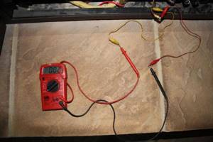
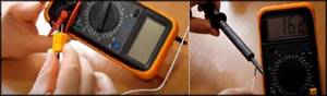
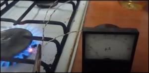
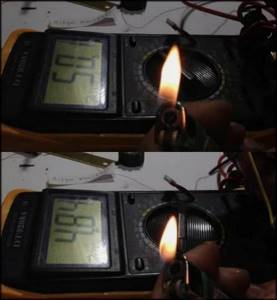
Checking a homemade thermocouple for a multimeter
We connect the electrodes of the assembled sensor to the multimeter in the same way as probes. Then you measure the environment: heat the head with a lighter and observe the tester display. In our case, the multimeter showed a voltage of 50 mV and a current of 5 μA, this is the maximum value for this homemade product.
Calibration
You can calibrate a homemade thermocouple and create a database of which value corresponds to which temperature by lowering the TC into a liquid with a previously known temperature (you will need to heat it up significantly). All that remains is to compare t° with the multimeter readings and write down the digital correspondences.
Other homemade products
We have described a method for creating a “bare” sensor; the processing device was already ready - a multimeter. With your own hands, you can create other receivers for such a thermocouple on Arduino, ATmega microcontrollers, as well as amplifiers on similar microcircuits - they will be required, since the EMF is very low.
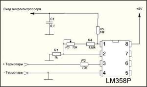
For homemade products, a popular microcontroller amplifier for thermocouple LM358P/LM358D for the range 0…+70° C.
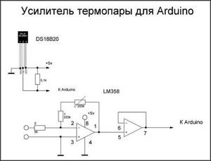
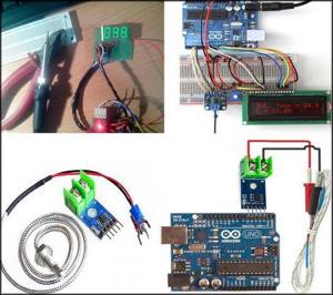
There are many drawings on the net on how to make a thermocouple for various tasks with Arduino, ATmega microcontrollers and with a digital display.
principle of operation, how to check the device with a multimeter and how it works, what it is
The thermocouple for a gas boiler has a simple design, so it is quite easy to repair. A gas boiler is a complex structure that requires additional components. Particularly important in this device are the parts that control its operation and protect against overheating. One of the most important components of a gas boiler is a thermocouple. Let's figure out what it is and how to repair it yourself.
Checking, repairing and replacing the thermocouple
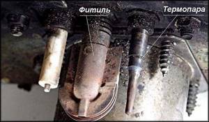
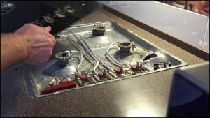
Let's consider malfunctions using the example of a thermocouple in a gas boiler sensor; in such devices it is also called a flame sensor. Along the way, we will reveal some of the nuances of operating thermoelectric detectors, how they are designed, and what such a device consists of.
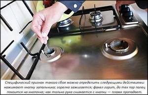
Signs of damage:
- fading of the wick at the moment when the ignition button is released at the same time;
- the light remains, but after the main burner is ignited, the fuel supply is shut off again and the boiler goes out altogether.
Causes:
- electrodes, hot junction are covered with soot, do not warm up enough. Therefore, the voltage on the circuit drops below the critical minimum required for the device to operate;
- burnout of the protective capsule of the TP;
- broken contacts at the junction point, broken wire;
- the fastening nuts have come loose;
- distortion of the working rod and, as a consequence, poor heating by the igniter;
- The traction sensor is broken or its electrical circuit is broken.
Repair, restoration
Thermocouples are sensitive to any damage and contamination: these factors can reduce the voltage output by the sensor below a critical limit. A typical common cause of poor performance is carbon deposits and soot on the working (heated) segment. To restore it, it is enough to clean it with a soft brush or cotton wool with alcohol. It is important to prevent scratches and mechanical damage. After cleaning, you need to check with a multimeter.
Often the cause of malfunctions is oxidized contacts; they can be cleaned with fine-grain sandpaper, but without excessive force.
Thus, if there is carbon deposits, soot, oxidation, loose or broken contacts, fasteners, etc., then the TP can be repaired. But if deep black dents or burnouts (holes) are found, then such an element is usually not restored. Theoretically, you can build a new protective casing and try to re-solder the ends if they have come apart, but there is no guarantee that such a repair will be of high quality. And from ineffective operation there is a risk of significant deterioration in the service life of the device, the likelihood of emergency situations increases. Almost always, sensors with such critical listed failures are replaced with new ones without hesitation.
Spare parts are sold in specialty stores and service points. Selecting one will not be difficult - just select a detector that is similar or has parameters that are suitable for a specific equipment model. Replacement is simple - snap off the old TP and connect (plug) the new one into the seats.
The only difficulty may be that the device will have to be disassembled, covers removed, assemblies with burners, and so on.
Malfunction of boiler devices
As for gas boilers, among all the equipment parts, it is the thermocouple that most often fails. A fault can be detected in the same way as in the case of a stove. The sign looks like this: the gas supply button is pressed, the igniter is ignited and held for 30 seconds (as required by the instructions) and released. In this case, the burner immediately goes out, which should alert you.
This may indicate that the thermocouple is faulty and requires replacement because it cannot be repaired. Or there is poor contact between the device and the solenoid valve.
In this case, you can perform simple diagnostics yourself and completely eliminate the problem, without involving a specialist. In this case, it is not necessary to know exactly what the operating principle of a thermocouple is. Here's what you need to do:
- The clamping nut is unscrewed, which holds the thermocouple to the solenoid valve, after which the device is removed.
- Carefully inspect the connector - are there any oxides or contamination? If something happens, go over it with fine sandpaper.
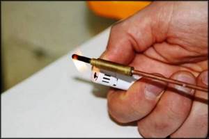
- Check functionality using a multimeter. To do this, one end of the device is connected to the device, and the other needs to be heated. You can use a hand-held gas burner or something else (candle). A working thermocouple should have a voltage of up to 50 mV.
- If the diagnosis was successful, all that remains is to install the thermocouple in its place and start the boiler again.
Anyone who knows what a thermocouple is can come to the correct conclusion - it's all about the solenoid valve itself. However, it can also be correct. Then you need to clean the junction of the conductors, and then find a good position for the clamping nut, which ensures good contact.
Which thermometer to choose: with a thermocouple or with a thermistor
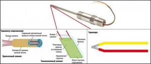
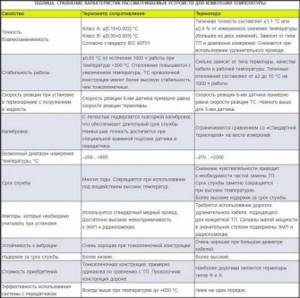
The design and principle of operation of a thermocouple in a thermoelectric meter and a thermistor in a resistance thermometer:
It is impossible to unambiguously recommend for all situations which detectors are the best: a thermometer with a thermocouple or with a thermistor (TC, also known as a resistance thermometer), since the environment must be taken into account and compared with the properties of these types of temperature sensors - each has its own pros and cons. We examined them in detail. Now let's describe an example of selection.
First of all, compare the characteristics, compare:
- with the required accuracy. For not particularly demanding purposes, a deviation of 1–2 degrees will not be critical. But for devices that require precision, this parameter is important. In most cases, thermistors are more correct, but this parameter can also be equal for different sensor models, as we see in the table;
- with operating temperature range. Here the TP is undoubtedly better, it covers the scope t° much wider;
- The reaction speed is better with thermocouples, but this is a general rule. This parameter can also be compared (see table);
- thermoelectric converters are better able to withstand vibrations, mechanical loads, and aggressive environments.
It is necessary to determine the best version of the device, taking into account all the nuances and goals. Let's describe this with an example:
- serviced area - a pipeline segment with constantly changing conditions and vibrations. Temperature −200…+300° C;
- the goal is maximum accuracy, and this is the most important condition;
- You can select both types of temperature sensors. At first glance, the TP is more suitable, since it is more resistant to loads and vibration;
- In the end, a thermistor device was chosen, since the goal is accuracy, and this type of sensor has higher accuracy. In addition, a thin-film thermistor was used; this version of the sensor is more resistant to vibration and loads.
Second example:
- environment - reactor, +550...+900° C, low vibration level;
- target - accuracy ±5° C;
- TCs provide consistently accurate measurements, especially at low vibrations, but we must not forget about the t° range. Thermistors should not be used at temperatures above + 850° C. Since our environment is +900, a thermometer with a thermocouple was chosen.
Advantages
A clearer understanding of the thermocouple and its operating principle in simple terms can provide the benefits available. The wide range of applications of such devices is precisely due to a number of advantages:
- Performs several functions: controls the flame and measures the temperature.
- There is nothing complicated in the design of these elements, since there are no additional parts.
- Ability to withstand a wide range of measured temperatures.
- High measurement accuracy, due to which gas boilers and water heaters are equipped with these devices.
- Easy installation and maintenance, which absolutely any private property owner can handle.
- Long service life.
- Reliability.
- Due to the simplicity of the design, thermocouples are easy to manufacture.
All these and many other advantages that thermocouples for modern boilers have are familiar to most manufacturers of gas equipment.
And now with their help you can ignite a stove or boiler more safely than before. We, as ordinary consumers, also understand why such devices are so popular.