Request a price
The process of heat transfer is called heat exchange. The devices in which the process occurs are heat exchangers. If the process involves two agents separated by a partition, these are surface recovery devices. The process of mixing warm and cold flows by contact occurs - a mixing heat exchanger.
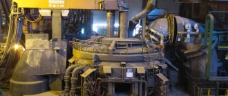
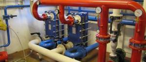
Heat exchange systems, why a heat exchanger is needed
An example of a mixing device is a cooling tower. The exhaust gases give off heat to the water sprayed from the nozzles. In devices where two agents flow through separate circuits, heat is transferred through the wall or surface.
A sign of a heat exchanger is a developed surface and the connection of two systems. It can be steam-water, antifreeze-water, water-water. Instead of water, a chemical solution is used in the process, and heated gases are used instead of steam.
The use of heat exchangers allows:
- Use residual heat to generate electrical energy.
- Carry out chemical processes in precise mode, maintaining the temperature with heat exchangers.
- Use secondary heat from energy carriers for domestic needs.
- Maintain the temperature of the coolant for domestic heating systems in parameters that comply with the standard.
Operating principle using the example of a plate heat exchanger
This heat exchanger was not chosen easily. It has a rather complex operating principle , and therefore ideally highlights some of the general features of each type of unit.
Each of the device plates is mounted to another part with a rotation of 180 degrees. In the standard composition of the device you can find up to four similar elements. Together they create packages that are responsible for the collector circuit. The circuit itself functions to create coolant movement. The design of the heat exchanger implies the presence of two extreme circuits. They are the ones who do not participate in the process of creating heat by the mechanism. Today, equipment manufacturers offer the user two different types of configuration.
- One-way. The coolant is divided and creates parallel flows. Almost immediately they flow into the outlet port.
- Multi-pass. This option involves the use of a complex circuit. The heat exchanger begins its movement along the same number of channels involved. This principle of operation implies the presence of additional elements (plates), which end with plugs in the outlet ports. This feature adds complexity to the maintenance of such elements.
Operating principle of the heat exchanger
The operating principle of surface heat exchangers is very simple. The coolant and heat consumer, isolated from each other, transfer heat to each other through the material that is located between them. Depending on the design, these may be pipes or plates. For these purposes, thermally conductive materials are used, for example, stainless steel, alloys and other materials. As a result, the medium passing through the heat exchanger transfers heat to the refrigerant without contacting it. The key operating principle of surface heat exchangers is that the media do not contact, i.e. do not mix.
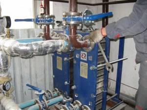
Heat exchanger installation
Using the installation instructions, it is necessary to secure the heat exchanger correctly. It is pressed against the wall using a special console or fastening tape. You can also install a heat exchanger using a corner that is attached to the bottom of the heat exchanger. Plus it will get tied up with pipes.
Additionally, filters need to be installed. There must be at least a coarse filter for the thermal power plant circuit. If connected to an old heating system, then two filters are required. One below, one above.
We need cranes and American women. The latter are quick-release threaded connections. As a rule, an ordinary simple American one consists of four parts: two threaded fittings, a union nut and a gasket.
A very important point during installation is the connection diameter, because the device is quite compact. It contains a small volume of coolant. The gap between the plates is minimal. It is advisable to take the same diameter that we need, or larger. For example, 1 inch connection. It is better to take the heat exchanger power level with a reserve. This does not affect the dimensions. Literally one or two centimeters more. But the rate of heat removal increases significantly. This is especially important in systems where the thermal power plant produces a low temperature. For example, with a maximum water temperature of 65-70 °C, this fact must be taken into account in order to remove the maximum possible amount of heat energy from the coolant.
Types of surface heat exchangers
The simplest t/o is a pipe in a pipe. A cold tube containing water passes through a larger pipe filled with a hot agent. In this case, the surface of the inner tube heats up and transfers heat to the water. This is how boilers work. If there are many tubes and they are collected in a bundle, then a shell-and-tube heat exchanger is obtained. Devices with a tube bundle secured at the ends with gratings are common in industry and used for domestic water treatment.
Twisted heat exchangers are coils wound in a housing. The interpipe space is filled with another flow. The equipment is used when the pressure of one of the agents is high.
Two-pipe heat exchangers are used to transfer heat in gas-liquid phases. The devices can operate under pressure with high heat transfer.
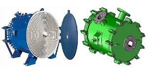
Spiral t/o
Spiral heat exchangers represent a barrel in which a flat labyrinth with an internal cavity is located like a spiral ribbon. A hot agent moves in a spiral, washed by cold water. The design is difficult to manufacture. But this is the only type of apparatus for heat exchange of an agent containing suspensions, pulp. Hinged lids on both sides allow for easy cleaning of gaps.
The plate heat exchanger is a special design of heating pipes assembled in the form of a flat element of their finned pipes and multi-pass water movement. The plates resemble accordions. Their disadvantage is that they become clogged with scale due to poor water treatment.
Why do you need a heat exchanger in a heating system? Imagine that the water in the pipes is 900. This will lead to rupture of plastic pipes and burns. Each thermal unit has a heating system that allows maintaining temperature parameters.
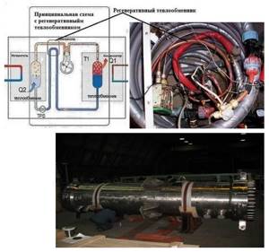
Recuperative heat exchangers
Recuperative heat exchangers are installations operating in periodic or stationary thermal mode. Batch-operating devices are usually large-capacity vessels, which at certain intervals are filled with the material being processed or one of the coolants, heated or cooled, and then removed. As a rule, continuous devices operate in stationary mode. The designs of modern recuperative heat exchangers are very diverse and are designed to work with liquid-liquid, vapor-liquid, gas-liquid coolants.
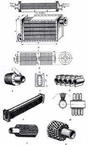
Continuous heat exchangers are used much more often , among which shell-and-tube heat exchangers are most widespread (Fig. 1). Shell-and-tube heat exchangers are devices made of tube bundles held together by tube sheets and limited by casings and covers. The pipe and inter-tube spaces in the apparatus are separated, and each of them is divided by partitions into several passages.
In shell-and-tube heat exchangers, pipes with an internal diameter of at least 12 mm and no more than 38 mm are usually used, since as the diameter of the pipes increases, the compactness of the heat exchanger significantly decreases and its metal consumption increases.
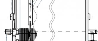
The length of the tube bundle ranges from 0.9 to 5...6 m. The thickness of the pipe wall is from 0.5 to 2.5 mm. Tube sheets are used to secure pipes in them using flaring, sealing or gland connections. The casing of the apparatus is a cylinder welded from one or more steel sheets. It is equipped with flanges to which the covers are bolted. The thickness of the casing wall is determined by the maximum pressure of the working medium and the diameter of the apparatus, but is not made thinner than 4 mm. Due to the difference in temperatures of the heating and heated media, the casing and pipes of the operating apparatus also have different temperatures. To compensate for stresses arising as a result of differences in temperature expansion of pipes and casing, lens compensators, U- and W-shaped pipes, and heat exchangers with floating chambers are used (Fig. 1).
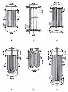
Rice. 1. Shell and tube recuperative heat exchangers : a, b - with rigid fastening of pipes in tube sheets; c - with lens compensators in the body; d, e - with U- and W-shaped tubes; e - with lower floating distribution chamber
In order to intensify heat transfer, the speed of coolants with a low heat transfer coefficient is increased, for which purpose the heat exchangers for the coolant passing in the pipes are made two-, four- and multi-pass, and segmental or concentric transverse partitions are installed in the interpipe space (Fig. 1).
If the pressure drops between the heating and heated media in the apparatus reach 10 MPa or more, coil heat exchangers with twisted pipes are used (Fig. 2, a), the ends of which are welded into distribution manifolds or into tube sheets that are smaller in size than in shell-and-tube apparatuses. These devices are more compact and also allow for higher speeds and heat transfer coefficients from the coolant moving in the pipes in the case of low flow rates.
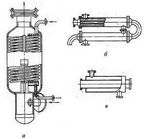
Rice. 2. Coil and sectional recuperative heat exchangers : a - with a twisted tubular heating surface (coil); b - sectional; c - “pipe in pipe”
Sectional heat exchangers (Fig. 2, b), like shell-and-tube heat exchangers, are used in a wide variety of areas. They are characterized by a smaller difference in velocities in the inter-tube space and in the pipes at equal coolant flow rates than in shell-and-tube devices. From these it is convenient to select the required heating surface area and change it if necessary. However, sectional heat exchangers have a large share of expensive elements - tube sheets, flanges, transition chambers, rolls, compensators, etc.; the metal consumption per unit heating surface is higher, the coolant path length is longer, and therefore the energy consumption for pumping it is higher. In the case of low thermal powers, the sections are made according to the “pipe-in-pipe” type of heat exchangers, in which a single inner pipe of smaller diameter is inserted into the outer pipe (Fig. 2, c).
Collapsible multi-flow heat exchangers “pipe in pipe” have found application in technological installations of oil, chemical, gas and other industries at temperatures from -40 to +450 °C and pressures up to 2.5...9.0 MPa. To improve heat transfer, pipes may have longitudinal ribs or transverse helical knurling.
Spiral heat exchangers are devices in which the channels for coolants are formed by two sheets rolled into spirals on a special machine (Fig. 3). The distance between them is fixed by welded bosses or pins. In accordance with GOST 12067-80, spiral heat exchangers are wound from coiled steel with a width of 0.2 to 1.5 m with heating surfaces from 3.2 to 100 m2 with a distance between sheets of 8 to 12 mm and a wall thickness of 2 mm for pressure up to 0.3 MPa and 3 mm - up to 0.6 MPa. Foreign companies produce special heat exchangers from rolled material (carbon and alloy steels, nickel, titanium, aluminum, their alloys and some others) with a width of 0.1 to 1.8 m, a thickness of 2 to 8 mm with a distance between sheets of 5 to 25 mm. Heating surfaces range from 0.5 to 160 m2.
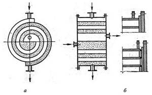
Rice. 3. Spiral heat exchanger : a - schematic diagram of a spiral heat exchanger; b - methods of connecting spirals with end caps
Spiral heat exchangers are installed using fittings horizontally and vertically. They are often mounted in blocks of two, four, eight devices and are used for heating and cooling liquids and solutions. Vertical devices are also used for condensation of pure vapors and vapors from vapor-gas mixtures. In the latter case, the condensate manifold has a fitting for removing non-condensable gas.
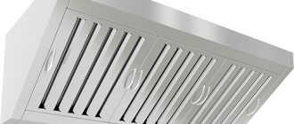
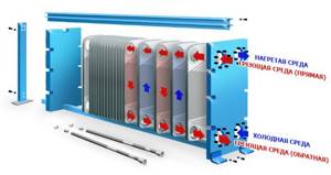
Plastic heat exchangers (Fig. 4, a, b) have slot-like channels formed by parallel plates. In the simplest case, the plates can be flat. To intensify heat transfer and increase compactness, the plates are given various profiles during manufacturing (Fig. 4, c, d), and profiled inserts are placed between the flat plates. The first profiled plates were made from bronze by milling and were characterized by increased metal consumption and cost. Currently, plates are stamped from sheet steel (carbon, galvanized, alloyed), aluminum, cupronickel, titanium and other metals and alloys. The thickness of the plates is from 0.5 to 2 mm. The heat transfer surface of one plate is from 0.15 to 1.4 m2, the distance between the plates is from 2 to 5 mm.
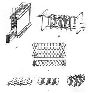
Rice. 4. Plate heat exchangers : a - plate air heater; b - collapsible plate heat exchanger for heat treatment of liquid media; c - corrugated plates; d - channel profiles between the plates; I, II - coolant inlet and outlet
Heat exchangers are made:
a) collapsible;
b) non-separable.
In dismountable devices, the channels are sealed using gaskets based on synthetic rubber. It is advisable to use them when it is necessary to clean surfaces on both sides. They can withstand temperatures ranging from -20 to 140...150 °C and pressures of no more than 2...2.5 MPa. Non-separable plate heat exchangers are welded. They can operate at temperatures up to 400 °C and pressures up to 3 MPa. Semi-collapsible heat exchangers are made from plates welded in pairs. Devices of the same type include block ones, which are assembled from blocks formed by several welded plates. Plate heat exchangers are used for cooling and heating liquids, condensing pure vapors and vapors from vapor-gas mixtures, and also as heating chambers in evaporators.
Finned heat exchangers (Fig. 5) are used in cases where the heat transfer coefficient for one of the coolants is significantly lower than for the second. The heat exchange surface on the side of the coolant with a low heat transfer coefficient is increased compared to the heat exchange surface on the side of the other coolant. From Fig. 5 (e...i) it can be seen that finned heat exchangers are manufactured in a wide variety of designs. The ribs are made transverse, longitudinal, in the form of needles, spirals, twisted wire, etc.
Pipes with external and internal longitudinal fins are produced by casting, welding, extraction from the melt through a die, and extrusion of metal heated to a plastic state through a matrix. Electroplating and painting are also used to secure fins to pipes and plates. To increase the efficiency of the fins, they are made from materials that are more heat-conducting than steel pipes: copper, brass, and often aluminum. However, due to the disruption of contact between the fin or ribbed jacket and the steel supporting pipe, bimetallic pipes are used at temperatures no higher than 280 °C, pipes with wound fins - up to 120 °C; wound fins rolled into a groove can withstand temperatures up to 330 °C, but quickly corrode at the base in polluted air and other aggressive gases.
Rice. 5. Types of finned heat exchangers : a - plate; b - cast iron tube with round ribs; c — tube with spiral fins; g - cast iron tube with internal fins; d — fin fins of tubes; e - cast iron tube with double-sided needle fins; g - wire (bispiral) fins of tubes; h—longitudinal fins of tubes; and - multi-fin tube
What determines the efficiency of a heat exchanger?
Shell and tube t/o
Surface heat transfer always occurs through the wall. In this case, heat loss occurs. The thinner the partition, the less loss. The new shell-and-tube heat exchanger has an efficiency of 75%, but as the internal and upper surfaces become overgrown with sediment, the efficiency of the device decreases. It cannot maintain temperature. Therefore, the devices have a removable beam, which is cleaned under high pressure with a special gun.
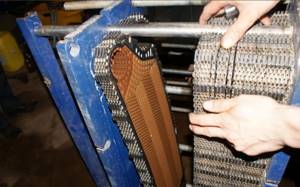
Plate devices have an efficiency of 90%, but the gaps between the plates become clogged and require cleaning. The equipment is disassembled for cleaning. It is important to install a magnetic mesh filter in place, which prevents the formation of sediment. Plate heat exchangers can be connected to automated control.
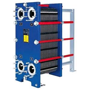
Plate collapsible t/o
The efficiency of the process depends on the connection diagram. Heat transfer is more complete in a counterflow apparatus when the flows move towards each other.
The thinner the partition, the better the process. But for pressure vessels, the wall thickness depends on the ability to withstand the load on the walls. If it is impossible to thin the walls of the tubes, it is necessary to increase the heating surface and make the apparatus longer.
Each heating unit is manufactured in accordance with thermal engineering calculations, has a passport and is designed to work with a specific coolant.
Heat transfer systems and features: the task of the heat exchanger
Plate heat exchangers can be used in various systems in industrial facilities and residential buildings.
In multi-storey buildings, preference is given to collapsible devices
In an apartment building
A standard dismountable device is often involved in connecting heating and hot water supply systems. There are several reasons for its installation in an apartment building:
- service life - from 25 years, but seals must be changed every 5-10 years;
- the device is easy to disassemble and can be repaired;
- the power can be adjusted independently by changing the number of plates.
This type of heat exchanger for heating is also suitable for industrial areas.
Self-repair of heating equipment is unacceptable
In a private house
In a private home, it is recommended to use a soldered heat exchanger for several reasons:
- suitable for aggressive environments;
- The service life of the device is 15 years;
- guarantees high efficiency due to minimal loss of thermal energy and high level of heat transfer;
- Since there are no seals in the design, leaks are impossible.
Assembling the device is quite simple and does not take much time.
The equipment requires regular checking of seals and descaling
Shell and tube heat exchangers
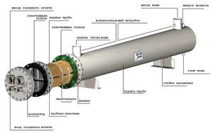
Shell and tube heat exchangers are designed for heating or cooling, evaporation or condensation of various liquid and vapor media in various technological processes.
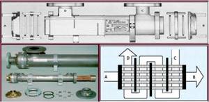
Rice. 21. The structure of a shell-and-tube heat exchanger, its main elements and a schematic diagram of the movement of coolants in it
Typically, shell-and-tube heat exchangers are used at coolant pressures of more than 2.5 MPa, and at lower pressures it is much more efficient to use plate heat exchangers.
Types of heat exchange equipment
- Superficial. The media exchange heat through the walls of the thermally conductive material. From the primary coolant, heat is transferred to the heat exchange surface and further to the secondary coolant. Contact surfaces are plates or tubes.
- Mixing. Heat is transferred directly between mixing media. Such installations are structurally simpler than surface ones, but are suitable only for those cases where coolants can be mixed. These include bubblers, cooling towers, and nozzle heaters.
Surface heat exchangers are divided into regenerative and recuperative:
- Regenerative (regenerators). Heat is transferred by alternating contact of media of different temperatures with one surface of the device. The movement of coolants is periodic: warm flow - cold flow.
- Regenerative. The media exchange heat continuously through the dividing surface. The direction of the flows is the same or opposite, but the routes do not change alternately (unlike regenerators), the heat exchange process is stationary.
In simple situations, when high heat transfer is not needed, single-pass devices are relevant - they are structurally simpler, require less maintenance, and are less dirty. Multi-pass units are used when the overall heat transfer coefficient needs to be increased. This is achieved by increasing the contact area of the media with the heat exchange surface.
Mixing heat exchangers
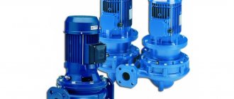
A mixing heat exchanger (or contact heat exchanger) is a heat exchanger designed to carry out heat and mass transfer processes by direct mixing of media (as opposed to surface heat exchangers) (Fig. 36-38). The most common steam-water jet devices are PSA - jet-type heat exchangers based on a jet injector. Mixing heat exchangers are structurally simpler than surface ones and use heat more fully. However, they are suitable only in cases where the technological conditions of production allow mixing of working media.
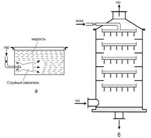
Rice. 36. Schemes of mixing heat exchangers : a - jet mixer; b - scrubber (irrigation heat exchanger)
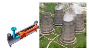
Rice. 37. Jet mixer (left) and cooling tower (right)
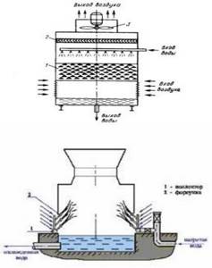
Rice. 38. Operating principles of irrigation heat exchangers
Regenerative heat exchangers
A regenerative heat exchanger is a heat exchanger in which the same surface is alternately washed with hot and cold coolants. When it comes into contact with a hot coolant, the wall accumulates heat and then releases it to the cold coolant. For satisfactory operation of the heat exchanger, its working walls must have significant heat capacity.
The heat exchange mode in regenerative heat exchangers is non-stationary. In order for the heat exchange process to proceed continuously with the same duration of heating and cooling periods, such a heat exchanger must have two sections operating in parallel.
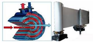
An example of a regenerative heat exchanger is rotary heat exchangers, which are widely used in supply and exhaust ventilation systems. The principle of their operation is shown in Fig. 33.
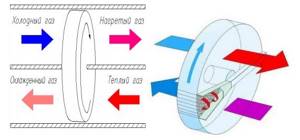
Rice. 33. Operating principle of regenerative rotary heat exchangers
Rice. 34. Regenerative heat exchangers
An example of a regenerative heat exchanger is also a regenerative air heater (Fig. 35), in which in the upper chamber a continuously moving nozzle is heated by the heat of the flue gases, and in the lower chamber it is cooled by air, which is heated to the required temperature.
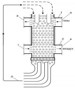
Rice. 35. Regenerative heat exchanger for heating air with flue gases : 1 - gas chamber; 2 - air chamber; a - supply of hot gases from the furnace, b - exhaust gas removal; c - cold air supply; g - hot air removal; e - supply of bulk packing; d - removal of bulk nozzle and return of cooled nozzle
Spiral heat exchangers
The spiral heat exchanger was invented in the twenties of the twentieth century by the Swedish engineer Rosenblad for use in the pulp and paper industry. These heat exchangers made it possible for the first time to ensure reliable heat transfer between media containing solids. In the 1970s, the design of spiral heat exchangers was radically changed and improved, and gained great advantages over the Rosenblad design.
Two or four long sheets of metal are laid in a spiral around a central pipe, forming two or four single-flow channels. To ensure a constant gap size, separating spikes are welded to one side of the sheets. The central pipe is divided into two chambers using a special partition, which form the inlet and outlet manifolds. The twisted spirals are placed in a cylindrical casing. The outer ends of the spiral sheets are welded along the forming shell. To allow the channels to exit to the outside, holes are drilled in the casing where the edges of the channels are fixed, which are hermetically sealed with inlet and outlet manifolds with connecting pipes.
The movement of flows in spiral heat exchangers occurs along curved channels, similar in shape to concentric circles. The direction of the flow velocity vectors is constantly changing. The channel geometry and dividing spikes create significant turbulence even at low flow rates, while improving heat transfer and reducing fouling.
This provides a compact design for spiral heat exchangers that can be integrated with any process line, significantly reducing installation costs.
Rice. 22. Spiral heat exchangers
Types of heat exchangers
Heat exchange units can be of various types. Their difference lies in the method of transferring thermal energy. The following types of presented devices are distinguished:
- Mixing . In them, the transfer of thermal energy is carried out by mixing two working media . These devices are much simpler in design than surface devices. It is possible to use such units only if it is possible to mix heat carriers. This condition is the main disadvantage of mixing devices.
- Superficial . In them, energy is exchanged between working heat carriers through the walls of the separator . Such devices are divided into recuperative and regenerative. In recuperative systems , when thermal energy is transferred through the dividing wall, the heat flow moves in one direction at each point of the wall . of a regenerative heat exchanger that the heat carrier, when alternately touching the same surface, changes the direction of flow from time to time .
Design and principle of operation
Modern models of heat exchange devices have several parts. Each has its own important role:
- fixed plate - all incoming pipes are attached to it;
- pressure plate;
- plates equipped with inserted sealing type gaskets;
- top and bottom guides;
- rear pillar;
- threaded studs.
This unique design of the heat exchange device makes it possible to achieve the most efficient layout of the entire surface of the operating unit.