Calculation of heat exchangers and various methods for drawing up a heat balance
When calculating heat exchangers, internal and external methods for drawing up a heat balance can be used. The internal method uses heat capacity values. The external method uses specific enthalpy values.
When using the internal method, the heat load is calculated using different formulas, depending on the nature of the heat exchange processes.
If heat exchange occurs without any chemical and phase transformations, and, accordingly, without the release or absorption of heat.
Accordingly, the thermal load is calculated using the formula
If during the heat exchange process steam condensation or liquid evaporation occurs, or any chemical reactions occur, then another form is used to calculate the heat balance.
When using the external method, the heat balance is calculated on the basis that an equal amount of heat enters and exits the heat exchange apparatus over a certain unit of time. If the internal method uses data on heat exchange processes in the unit itself, then the external method uses data from external indicators.
To calculate the heat balance using the external method, the formula is used.
Q1 refers to the amount of heat that enters and exits the unit per unit time. By means the enthalpy of substances that enter and leave the unit.
You can also calculate the enthalpy difference in order to establish the amount of heat that was transferred between different media. The formula is used for this.
If any chemical or phase transformations occurred during the heat exchange process, the formula is used.
Selection of heat exchanger
Based on the calculations made, which we indicated above, the output is a set of parameters and their values, for example, the speed of water flow in the pipes, their diameter, heat exchange area, etc.
Next, we move on to selecting a device that fits the calculation. Special software from leading manufacturers of heat exchangers: Ridan, Alfa Laval, GEA, etc. allows you to select a heat exchanger model accurately and quickly. Engineers use the most modern versions of such software.
If you want to delve into the specifics of selecting and calculating heat exchangers, we recommend subscribing to our news and e-mail newsletter.
If you need to select a heat exchanger “here and now,” then fill out the selection form below.

Heat transfer mechanisms in the calculation of heat exchangers
Heat exchange occurs through three main types of heat transfer. These are convection, conduction and radiation.
During heat exchange processes that proceed according to the principles of the mechanism of thermal conductivity, heat transfer occurs as the transfer of energy of elastic vibrations of molecules and atoms. This energy moves from one atom to another in the direction of decrease.
When calculating heat transfer parameters based on the principle of thermal conductivity, Fourier's law is used:
To calculate the amount of heat, data on flow time, surface area, temperature gradient, and thermal conductivity are used. The temperature gradient refers to its change in the direction of heat transfer per unit length.
The thermal conductivity coefficient refers to the rate of heat transfer, that is, the amount of heat that passes through one unit of surface per unit of time.
In any thermal calculations, it is taken into account that metals have the highest thermal conductivity coefficient. Various solids have a much smaller coefficient. And for liquids this indicator is usually lower than for any of the solids.
When calculating heat exchangers, where heat is transferred from one medium to another through a wall, the Fourier equation is also used to obtain data on the amount of heat transferred. It is calculated as the amount of heat that passes through a plane with an infinitesimal thickness: .
If we integrate the indicators of temperature changes over the wall thickness, we get
Based on this, it turns out that the temperature inside the wall drops according to the law of a straight line.
Convection mechanism of heat transfer: calculations
Another heat transfer mechanism is convection. This is the transfer of heat by volumes of a medium through their mutual movement. In this case, the transfer of heat from the medium to the wall and vice versa, from the wall to the working medium is called heat transfer. To determine the amount of heat that is transferred, Newton's law is used
In this formula, a is the heat transfer coefficient. With turbulent movement of the working medium, this coefficient depends on many additional quantities:
- physical parameters of the fluid, in particular heat capacity, thermal conductivity, density, viscosity;
- conditions for washing the heat-releasing surface with gas or liquid, in particular the speed of the fluid, its direction;
- spatial conditions that limit the flow (length, diameter, surface shape, its roughness).
Therefore, the heat transfer coefficient is a function of many quantities, as shown in the formula
The dimensional analysis method makes it possible to derive a functional relationship between similarity criteria that characterize heat transfer during the turbulent nature of flow in smooth, straight and long pipes.
This is calculated using the formula.
Heat transfer coefficient in the calculation of heat exchangers
In chemical technology, there are often cases of exchange of thermal energy between two fluids through a dividing wall. The heat exchange process goes through three stages. The heat flux for a steady process remains unchanged.
The heat flow passing from the first working medium to the wall, then through the wall of the heat transfer surface and then from the wall to the second working medium is calculated.
Accordingly, three formulas are used to carry out calculations:
As a result of the joint solution of the equations, we obtain
Magnitude
and is the heat transfer coefficient.
Calculation of average temperature difference
When the required amount of heat has been determined using the heat balance, it is necessary to calculate the heat exchange surface (F).
When calculating the required heat transfer surface, the same equation is used as in the previous calculations:
In most cases, the temperature of the working media will change during heat exchange processes. This means that the temperature difference will change along the heat exchange surface. Therefore, the average temperature difference is calculated. And due to the fact that the temperature change is not linear, the logarithmic difference is calculated. Unlike direct flow, with countercurrent movement of working media, the required heat exchange surface area should be smaller. If both co-current and counter-current flows are used in the same course of the heat exchanger, the temperature difference is determined based on the relationship.
Calculation of average temperature difference
The heat exchange surface is calculated when determining the required amount of heat energy through a heat balance.
The calculation of the required heat transfer surface is carried out using the same formula as in the calculations carried out earlier:
The temperature of working media, as a rule, changes during processes associated with heat exchange. That is, the change in temperature difference along the heat exchange surface will be recorded. Therefore, the average temperature difference is calculated. Due to the nonlinearity of temperature changes, the logarithmic difference is calculated
Countercurrent movement of working media differs from direct flow in that the required heat exchange surface area in this case should be smaller. To calculate the difference in temperature indicators when using both countercurrent and co-current flows in the same heat exchanger passage, the following formula is used
The main purpose of the calculation is to calculate the required heat exchange surface area. Thermal power is specified in the technical specifications, but in our example we will also calculate it in order to check the technical specifications itself. In some cases, it also happens that there may be an error in the original information. Finding and correcting such an error is one of the tasks of a competent engineer. The use of this approach is very often associated with the construction of skyscrapers in order to relieve pressure from equipment.
Introduction
A heat exchanger is a device that provides heat transfer between media that differ in temperature. To provide heat flows of varying quantities, different heat exchange devices are designed. They can have different shapes and sizes depending on the required performance, but the main criterion for choosing a unit is its working surface area. It is determined using thermal calculations of the heat exchanger during its creation or operation.
The calculation can be of a design (construction) or testing nature.
The end result of the design calculation is the determination of the heat exchange surface area required to ensure the specified heat flows.
The verification calculation, on the contrary, serves to establish the final temperatures of the working coolants, that is, heat flows for the available heat exchange surface area.
Accordingly, when creating a device, a design calculation is carried out, and during operation, a verification calculation is carried out. Both calculations are identical and, in fact, are reciprocal.
Calculation example
For greater clarity, let us present an example of a design calculation of heat transfer. This calculation has a simplified form and does not take into account heat losses and design features of the heat exchanger.
- Temperature of the heating medium at the inlet t1in = 14 ºС;
- Temperature of the heating medium at the outlet t1out = 9 ºС;
- Temperature of the heated medium at the inlet t2 in = 8 ºС;
- Temperature of the heated medium at the outlet t2out = 12 ºС;
- Heating medium mass consumption G1 = 14000 kg/h;
- Mass consumption of heated carrier G2 = 17500 kg/h;
- Standard value of specific heat capacity ср =4.2 kJ/kg‧ ºС;
- Heat transfer coefficient k = 6.3 kW/m2.
1) Let's determine the power of the heat exchanger using the heat balance equation:
Qin = 14000‧4.2‧(14 – 9) = 294000 kJ/h
Qout = 17500‧4.2‧(12 – = 294000 kJ/h
Qin = Qout. The heat balance conditions are met. Let's convert the resulting value into the unit of measurement W. Provided that 1 W = 3.6 kJ/h, Q = Qin = Qout = 294000/3.6 = 81666.7 W = 81.7 kW.
2) Determine the value of pressure t. It is determined by the formula:
3) Let's determine the heat transfer surface area using the heat transfer equation:
F = 81.7/6.3‧1.4 = 9.26 m2.
As a rule, when carrying out a calculation, not everything goes smoothly, because it is necessary to take into account all sorts of external and internal factors that influence the heat exchange process:
- features of the design and operation of the device;
- energy loss during device operation;
- heat transfer coefficients of thermal carriers;
- differences in work on different parts of the surface (differential nature), etc.
You can independently carry out a thermal calculation based on the equations above and get the result in pdf format (in the fields “Allowable losses”, “Calculation pressure” and “Tmax” you can specify arbitrary data, the only limitation is: Tmax > t1).
IMPORTANT: For the most accurate and reliable calculation, the engineer must understand the essence of the process of heat transfer from one body to another. He should also be provided with the necessary normative and scientific literature as much as possible, since, based on many quantities, appropriate standards have been drawn up, which the specialist must adhere to.
How to calculate a heat exchanger for heating
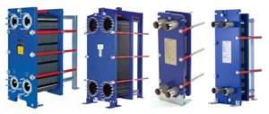
Calculation of plate heat exchanger
First, we will look at what types of heat exchangers there are, and then we will look at the formulas for calculating heat exchangers. And Tables of various heat exchangers by power.
AlfaLaval brazed heat exchanger - non-separable!
AlfaLaval - Dismountable with rubber gaskets
The main purpose of heat exchangers of this type is the instantaneous transfer of temperature from one independent circuit to another. This makes it possible to receive heat from central heating to your own independent heating system. It also makes it possible to obtain hot water supply.
There are collapsible and non-separable heat exchangers! AlfaLaval
— Russian production!
AlfaLaval brazed heat exchanger - non-separable!
Brazed stainless steel heat exchangers do not require gaskets or pressure plates. The solder reliably connects the plates at all contact points, which ensures optimal heat transfer efficiency and high pressure resistance. The design of the plates is designed for a long service life. PPTs are very compact, since heat transfer occurs through almost the entire material from which they are made. They have low mass and small internal volume. Alfa Laval offers a wide range of devices that can always be adapted to specific customer requirements. Any problems related to heat transfer are solved by PPT in the most economically efficient way.