Operating principle
The best example that will show the operating principle of a heating elevator would be a multi-storey building. It is in the basement of a multi-story building that you can find an elevator among all the elements.
First of all, let's look at the drawing of the elevator heating unit in this case. There are two pipelines: supply (it is through it that hot water goes to the house) and return (cooled water returns to the boiler room).
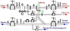
Diagram of an elevator heating unit
From the thermal chamber, water enters the basement of the house; there is always a shut-off valve at the entrance. Usually these are valves, but sometimes in those systems that are more thought out, steel ball valves are installed.
As the standards show, there are several thermal regimes in boiler rooms:
- 150/70 degrees;
- 130/70 degrees;
- 95(90)/70 degrees.
When the water heats up to a temperature no higher than 95 degrees, the heat will be distributed throughout the heating system using a collector. But at temperatures above normal - above 95 degrees, everything becomes much more complicated. Water at this temperature cannot be supplied, so it must be reduced. This is precisely the function of the elevator heating unit. We also note that cooling water in this way is the simplest and cheapest way.
Thermal unit diagram
Each building, be it a private house or a multi-storey apartment, is equipped with several life support systems. One of them is the heating system. Residents of multi-storey buildings may be surprised, but in their basement there is a special place called a heating unit or heat metering point. In this article we will talk about it in more detail.
You will learn what a thermal energy metering unit is, what it is needed for, how it functions, and who can service it.
We reveal the veil - what is UUTE
For those who are hearing this term for the first time, we will explain its meaning. UUTE is not just a device, but a complex of equipment. The installation of each of them is necessary in order to provide fundamental accounting and regulation of energy, adjusting the volume of coolant inside. The system registers and monitors parameters. Installation of such equipment is carried out on heating pipes in the basement of a multi-storey building.
Here are the main pieces of equipment:
- Calculator.
- Shut-off valves.
- Sensors indicating pressure and temperature in the system.
- Pressure, flow and temperature transducers.
Why is such a system needed? All this was technological data; to put it simply, the heat metering unit is installed at the entrance of pipes into the house. Its main task is to change the parameters of the internal coolant. What does it mean? Before the coolant reaches your heating device (convector or radiator), the heating unit begins to reduce its pressure and temperature. Have you noticed that the heating pipes in the house are always the same temperature, you cannot get burned on them. This is even beneficial not only for you, but also for the entire heating system. Nowadays, metal pipelines are replaced with polypropylene or metal-plastic ones. They do not like high temperatures and high pressure.
Here are some regulated operating modes of the thermal energy metering unit:
What do these numbers mean? They indicate the maximum and minimum permissible temperature values of the coolant in the pipes. Each unit is equipped with a heat meter.
Types of installation diagrams for thermal units
It becomes clear that the heating unit in an apartment building is located in the basement, where the heat supply to each apartment begins. The diagram of the thermal unit is shown in this photo.
As you can see from the picture, this is an elevator circuit. It can be called the simplest and least expensive. But the disadvantage of this system is that it is impossible to regulate the temperature in the pipes. In this regard, some inconveniences arise for end consumers. Thermal energy is overused during the thaw during the heating season. The main structure of such a scheme is an elevator. And a pressure reduction reducer can be installed in front of it. And the elevator itself serves to mix the cooled coolant with the hot one. At its output, a vacuum is created, which serves as the basis for the work. Due to this vacuum, the coolant in the elevator is under less pressure, which is why mixing occurs.
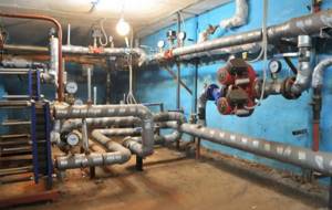
But, there is another scheme for installing the system. It works on the basis of a heat exchanger. You can see it in this photo.
Due to the fact that the heating point is connected through this same heat exchanger, the coolant inside the house and the coolant from the heating main are separated. And due to this division, it is possible to carry out its preparation. Additives and filtration are used for this purpose. It is this scheme that opens big doors for regulating the temperature and pressure of the coolant in the pipes. Why is it important? The fact is that the circuit based on a heat exchanger allows you to reduce heating costs.
If we talk about mixing the coolant, then for such a system it is done through thermostatic valves. A special feature of the use is that residents can afford to use aluminum radiators. But there is a small nuance - if the coolant inside the system is of poor quality, the service life of the radiators is reduced. Naturally, you will not be able to control the quality of the coolant inside. That's why it's better not to take risks and be content with bimetallic or cast iron radiators.
Note! When connecting DHW through a heat exchanger, it becomes possible to control the pressure inside and the water temperature. I would like to note that some managers who like to make money from conscientious payers may engage in deceiving the residents of the house. How? Lowering the water temperature by just a few degrees. As a result, it turns out that consumers do not notice this difference, however, taking into account the entire house, we can conclude that managers will be able to earn several tens of thousands of rubles in just one month.
Energy metering unit maintenance
Can any resident of a multi-storey building perform maintenance on thermal energy metering units? No. If we talk about installation or maintenance of the energy metering system, then all this is carried out by specially trained personnel who have been instructed and authorized to perform this work. The thing is that such a place is a high-risk area. Not only can you damage the equipment by paying tens of thousands, but you will also suffer.
That’s why you shouldn’t go inside and “make” everything your own way out of curiosity. Don't risk your health. If any problems arise, it is better to immediately report to the appropriate authorities. And to become more familiar with the thermal energy metering system, you can watch this video.
Conclusion
From this article you could learn more about what a heating unit and heat metering system are. As you can see, this is a must for multi-story buildings. By monitoring the temperature of the coolant inside, you can adjust it to the optimal value. This will save money on heating and extend the service life of your heating devices. In addition, I would like to say that such units can also be installed for a private house, if it is connected to centralized heating. Although the system will cost you a pretty penny, you will be able to ensure the maximum level of comfort in the future.
bouw.ru
General brief information about heat supply systems
In order to correctly understand the importance of the elevator unit, it is probably necessary to first briefly consider how central heating systems work.
CHP plant with a heating mains system
The source of thermal energy is thermal power plants or boiler houses, in which the coolant is heated to the required temperature through the use of one or another type of fuel (coal, oil products, natural gas, etc.) From there, the coolant is pumped through pipes to points of consumption.
A thermal power plant or a large boiler house is designed to provide heat to a certain area, sometimes covering a very large territory. Pipeline systems turn out to be very long and branched. How to minimize heat losses and distribute it evenly among consumers, so that, for example, the buildings most distant from the thermal power plant do not experience a lack of heat? This is achieved by careful thermal insulation of heating lines and maintaining a certain thermal regime in them.
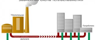
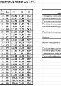
In practice, several theoretically calculated and practically tested temperature regimes for the operation of boiler houses are used, which ensure heat transfer over significant distances without significant losses, and maximum efficiency and economical operation of boiler equipment. So, for example, modes 150/70, 130/70, 95/70 are used (water temperature in the supply line / return temperature). The choice of a specific mode depends on the climate zone of the region and on the specific level of the current winter air temperature.
Simplified diagram of heat supply from thermal power plant (boiler house) to consumers
1 – Boiler house or thermal power plant.
2 – Consumers of thermal energy.
3 – Heated coolant supply line.
4 – “Return” highway.
5 and 6 – Branches from highways to consumer buildings.
7 – In-house heat distribution units.
From the supply and return mains there are branches to each building connected to this network. But here questions immediately arise.
- Firstly, different objects require different amounts of heat - you cannot compare, for example, a huge residential high-rise and a small low-rise building.
- Secondly, the temperature of the water in the main does not meet the permissible standards for supply directly to the heat exchange devices. As can be seen from the above modes, the temperature very often even exceeds the boiling point, and water is maintained in a liquid aggregate state only due to high pressure and the tightness of the system.
The use of such critical temperatures in heated rooms is unacceptable. And it’s not just a matter of excess thermal energy supply – this is extremely dangerous. Any touch to batteries heated to this level will cause severe tissue burns, and in the event of even a slight depressurization, the coolant instantly turns into hot steam, which can lead to very serious consequences.
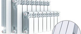
The correct choice of heating radiators is extremely important!
Not all heating radiators are the same. It's not only and not so much about the material of manufacture and appearance. They can differ significantly in their performance characteristics and adaptation to a particular heating system.
How to choose the right heating radiators is in a special article on our portal.
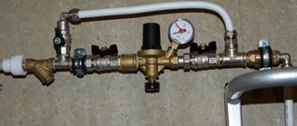
Thus, at the local heating unit of the house it is necessary to reduce the temperature and pressure to the calculated operating levels, while ensuring the required heat extraction sufficient for the heating needs of a particular building. This role is performed by special heating equipment. As already mentioned, these can be modern automated complexes, but very often preference is given to a proven elevator unit scheme.
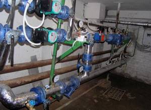
This is what a simple elevator unit in a residential building might look like
If you look at the heat distribution point of a building (most often they are located in the basement, at the entry point of the main heating networks), you will see a node in which a jumper is clearly visible between the supply and return pipes. This is where the elevator itself stands; the structure and principle of operation will be discussed below.
Construction of a thermal heating unit
The heating point of a heating system is the place where the hot water supplier's main line is connected to the heating system of a residential building, and the consumed thermal energy is also calculated.
Main types of heating points
The nodes connecting the system to a source of thermal energy are of two types:
- Single-circuit;
- Dual-circuit.
A single-circuit heating point is the most common type of consumer connection to a source of thermal energy. In this case, a direct connection to the hot water supply line is used for the heating system of the house.
A single-circuit heating point has one characteristic detail - its design includes a pipeline connecting the direct and return lines, which is called an elevator. The purpose of the elevator in the heating system is worth considering in more detail.
Boiler heating systems have three standard operating modes, differing in coolant temperature (direct/return):
- 150/70;
- 130/70;
- 90–95/70.
The use of superheated steam as a coolant for the heating system of a residential building is not permitted. Therefore, if, due to weather conditions, the boiler room supplies hot water at a temperature of 150 °C, it must be cooled before being supplied to the heating risers of a residential building. For this purpose, an elevator is used, through which the “return” enters the direct line.
The elevator opens manually or electrically (automatically). An additional circulation pump can be included in its line, but usually this device is made of a special shape - with a section of sharp narrowing of the line, after which there is a cone-shaped expansion. Due to this, it works like an injection pump, pumping water from the return line.
Double-circuit heating point
In this case, the coolants of the two circuits of the system do not mix. To transfer heat from one circuit to another, a heat exchanger, usually a plate one, is used. The diagram of a double-circuit heating point is shown below.
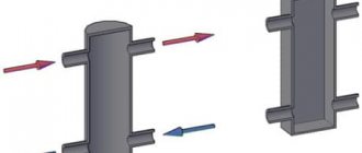
A plate heat exchanger is a device consisting of a number of hollow plates, through some of which the heating liquid is pumped, and through the others - the heated liquid. They have a very high efficiency, they are reliable and unpretentious. The amount of heat removed is regulated by changing the number of plates interacting with each other, so taking cooled water from the return line is not required.
How to equip a heating point
h3_2
To organize heat supply to a residential building, heating points are equipped with the following additional equipment:
- Valves and valves;
- Dirt filters;
- Control and accounting devices - thermometers, pressure gauges, flow meters;
- Auxiliary pumps.
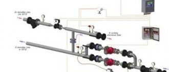
The composition of the equipment of a single-circuit heating point is shown in the figure.
The numbers here indicate the following nodes and elements:
- 1 - three-way valve;
- 2 - valve;
- 3 - plug valve;
- 4, 12 — mud collectors;
- 5 - check valve;
- 6 — throttle washer;
- 7 — V—fitting for thermometer;
- 8 — thermometer;
- 9 — pressure gauge;
- 10 — elevator;
- 11 — heat meter;
- 13 - water meter;
- 14 — water flow regulator;
- 15 — sub-steam regulator;
- 16 - valves;
- 17 - bypass line.
Installation of heat metering devices
Thermal metering equipment includes:
- Thermal sensors (installed in the forward and return lines);
- Flow meters;
- Heat calculator.
Heat metering devices are installed as close as possible to the departmental border so that the supplier company does not calculate heat loss using incorrect methods. It is best that thermal units and flow meters have gate valves or valves at their inputs and outputs, then their repair and maintenance will not cause difficulties.
Advice! There must be a section of the pipeline in front of the flow meter without changing the diameters, additional inserts and devices to reduce flow turbulence. This will increase the measurement accuracy and simplify the operation of the unit.
The thermal computer, which receives data from temperature sensors and flow meters, is installed in a separate locked cabinet. Modern models of this device are equipped with modems and can connect via Wi-Fi and Bluetooth to a local network, providing the opportunity to receive data remotely, without a personal visit to heat metering centers.
domotopim.ru
How a heating elevator works and works
Externally, the heating elevator itself is a cast iron or steel structure, equipped with three flanges for insertion into the system.
Elevator appearance
Let's look at its structure inside.
Diagram of the device and operating principle of the jet elevator
Superheated water from the heating main enters the elevator inlet pipe (item 1). Moving forward under pressure, it passes through a narrow nozzle (item 2). A sharp increase in the flow velocity at the nozzle exit leads to an injection effect - a vacuum zone is created in the receiving chamber (item 3). According to the laws of thermodynamics and hydraulics, water is literally “sucked” into this area of low pressure from the pipe (item 4) connected to the “return” pipe. As a result, in the mixing neck of the elevator (item 5), the hot and cooled flows are mixed, the water receives the temperature required for the internal network, the pressure decreases to a level safe for heat exchange devices, and then the coolant through the diffuser (item 6) enters the internal distribution system .
Scheme of a scheduled check of the operating condition of the elevator unit
One of the advantages of the system is ease of operation. The device does not require round-the-clock monitoring; routine inspections are sufficient. This kind of examination is best performed according to the following algorithm:
- Checking the integrity of pipes;
- Verification of instruments, adjustment of pressure sensors and thermometers;
- Calculation of pressure loss when water passes through the nozzle;
- Calculation of the displacement coefficient. This value must be taken into account when setting up the system, since even a perfectly mounted and installed unit and pipeline wear out over time.
After a routine inspection, the system is sealed to secure its settings and prevent unauthorized changes.
Installation of an elevator unit
As a rule, the installation of an elevator heating unit is carried out in the basement. The use of such a place is possible subject to a number of requirements:
- This must be an indoor room with a positive temperature (above 0°)
- Due to the large temperature difference, droplets of water settle on pipes in a humid room (condensation forms). This leads to rapid wear of the equipment. To keep the pipes dry, it is necessary to install an exhaust ventilation system.
Diagram of a heating system with an elevator unit
The elevator heating unit is a special design that performs the function of an injector or jet pump - and the need for this element arises only in centralized systems, where heated coolant is supplied from the boiler room under pressure. The heating circuit of the elevator unit is designed to ensure that the pressure in the system is increased. This need is realized by increasing the amount of coolant, i.e. The usual laws of physics apply.
When the air temperature outside reaches high negative values, the coolant temperature can exceed +150 degrees. Of course, this phenomenon contradicts the laws of physics - in central heating, ordinary water is used to transfer heat, which, when heated to the specified temperature, turns into a vapor state. Another thing is that water becomes steam only in open containers and in the absence of pressure - and the central heating system does not meet these conditions, so steam does not form.
Calculation
The operation of the elevator unit depends on the correctly selected dimensions and pressure difference between the discharge and return pipelines. To calculate the parameters of the elevator unit, heating engineers and programmers have created quite a lot of programs. They look like a regular screen form with a customized formula for calculations. After filling out all the rows of the table, the program calculates the parameters of the hot water supply scheme, the dimensions of the elevator and displays the results in the form of a diagram with plotted dimensions and in the form of a table with calculations. The option for displaying results is usually presented in the form of a table.
The calculation of the heating network and the choice of elevator is described in some detail in the Building Codes and Rules:
- SNiP 23-01-99 “Building climatology”, 2000;
- SNiP II-3-79 “Construction Heat Engineering”, 1998;
- SNiP 2.04.05-91 “Heating, ventilation and air conditioning”, 1987;
- Bogoslovsky V.N. “Internal sanitary installations”, 1990.
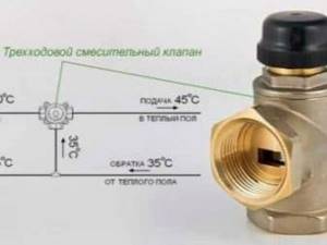
The mixing thermostat is an alternative to the standard elevator unit. It works in exactly the same way as an elevator - it mixes the hot water coming from the thermal power plant and the cooled water that returns from the radiators. Three channels are connected to the thermostat: one for hot water, the second for return, and the third for supplying the prepared mixture to the heating radiators. If the temperature of the water from the main pipeline is within acceptable limits, the cold flow is completely blocked. As soon as the temperature begins to rise, the valve gradually begins to open, a portion of cool water is added to the hot water, lowering the temperature of the mixture. The hotter the water, the larger the volume of cool water is added. A three-way mixing thermostat valve is necessary to control the proportion of cold and hot water in order to obtain the coolant at the optimal temperature. Advantages: small dimensions, no moving parts, easy temperature adjustment.
Air heating calculation
Before performing the calculation, you should know that air heating can be combined with ventilation. The progress of the calculations will depend on this, but in any case, the heat losses through the external walls, windows, roofing and floors for each room are first determined. To do this, use the formula given for the wall:
Qwalls = 1/Rwalls x (tв – tн) x Swalls, where:
Rwalls – heat transfer resistance, (m2 ºС / W); Swalls – wall area within the premises under consideration, m2; tв and tн – respectively, the temperature of the internal and external air.
The same formula is used to calculate heat loss from windows and other enclosing structures. Knowing the materials from which these structures are built or will be built, the heat transfer resistance R is calculated for each of them:
R = δ / λ, here:
δ – thickness of the structure in meters; λ – thermal conductivity coefficient of the material, W/(m ºС). This value is a reference value; it is easy to find in the technical literature.
The obtained values for all building structures protecting the room from the external environment are added up and we obtain the value of the thermal power of the heating system to compensate for losses through these structures. If it is necessary to calculate air heating combined with a ventilation system, then the thermal energy spent on heating the supply air is added to the resulting value. It is calculated using the formula:
We recommend: Do-it-yourself well drilling: what kind of drilling rig is used
Qvent = cm (tв – tн), where:
Qvent – energy spent on heating the supply air, W; m – mass of supply air, kg; tв and tн – temperature of internal and external air; с – specific heat capacity of the air mixture, equal to 0.28 W / (kg ºС).
To perform further calculations of the air heating system, you need to find out the mass of the air mixture m (kg). To do this, its quantity per m3 is first determined, after which it is multiplied by the density; its values at different temperatures are given in technical reference books. The amount of supply air for living rooms is taken according to their volume, which corresponds to an exchange rate of 1 time per hour.
Main malfunctions of the elevator unit
Even such a simple device as an elevator unit may not work correctly. Malfunctions can be determined by analyzing pressure gauge readings at control points of the elevator unit:
- Malfunctions are often caused by pipelines becoming clogged with dirt and solid particles in the water. If there is a pressure drop in the heating system, which is significantly higher before the sump tank, then this malfunction is caused by a clogged sump tank located in the supply pipeline. Dirt is discharged through the drain channels of the mud collector, and the meshes and internal surfaces of the device are cleaned.
- If the pressure in the heating system fluctuates, then possible causes may be corrosion or clogged nozzle. If the nozzle is destroyed, the pressure in the heating expansion tank may exceed the permissible limit.
- It is possible that the pressure in the heating system increases, and the pressure gauges before and after the sump tank in the “return” show different values. In this case, you need to clean the return dirt trap. The drain taps on it are opened, the mesh is cleaned, and contaminants are removed from the inside.
- When the size of the nozzle changes due to corrosion, a vertical misalignment of the heating circuit occurs. The radiators below will be hot, but on the upper floors they will not be heated enough. Replacing the nozzle with a nozzle with a calculated diameter eliminates this problem.
Switchgears
The elevator unit with all its piping can be thought of as a pressure circulation pump, which supplies coolant to the heating system under a certain pressure.
If the facility has several floors and consumers, then the most correct solution is to distribute the total coolant flow to each consumer.
To solve such problems, a comb is designed for the heating system, which has another name - a collector. This device can be represented as a container. The coolant flows into the container from the elevator outlet, which then flows out through several outlets, with the same pressure. Consequently, the distribution comb of the heating system allows the shutdown, adjustment, and repair of individual consumers of the facility without stopping the operation of the heating circuit. The presence of a collector eliminates the mutual influence of the heating system branches. In this case, the pressure in the heating radiators corresponds to the pressure at the elevator outlet.
Three way valve
If it is necessary to divide the coolant flow between two consumers, a three-way heating valve is used, which can operate in two modes:
- constant mode;
- variable hydraulic mode.
A three-way valve is installed in those places in the heating circuit where it may be necessary to divide or completely shut off the flow of water.
The tap material is steel, cast iron or brass. Inside the faucet there is a shut-off device, which can be ball, cylindrical or conical. The tap resembles a tee and, depending on the connection, a three-way valve on a heating system can work as a mixer. Mixing proportions can be varied within wide limits. The ball valve is mainly used for:
- adjusting the temperature of heated floors;
- adjusting battery temperature;
- distribution of coolant in two directions.
There are two types of three-way valves - shut-off and control valves. In principle, they are almost equivalent, but with three-way shut-off valves it is more difficult to regulate the temperature smoothly.
What is an elevator unit of a heating system
Trunk heating networks operate in three main modes:
- 95°/70°
- 130°/70°
- 150°/70°
The first number indicates the temperature of the coolant in the forward pipeline, the second – in the return. The coolant is transported over considerable distances, so the temperature is set taking into account the loss of thermal energy during movement and adjusted for climatic or weather conditions. Hence there are three options for supplying coolant - if you constantly heat water to the maximum value, fuel consumption will increase, so heating modes change depending on external conditions.
According to sanitary standards and technical characteristics of household heating equipment, the upper limit of coolant temperature should not exceed 95°. If the water is heated to 130° or 150°, it must be cooled to the set value. There are several reasons for this:
- Most heating devices are not able to work with overheated water - cast iron radiators become brittle, aluminum radiators may fail or cease to maintain system pressure.
- The pipelines used to supply coolant in apartments also have a temperature limit; for example, for plastic pipes a temperature threshold of 90° is set.
- Heating appliances that are too hot are dangerous for people, especially children.
Superheated water does not turn into steam only because there is no such possibility inside the pipelines. It requires the absence of pressure and the presence of free space, which cannot exist in a pipe. Temperature losses during transportation somewhat change the thermal regime of the coolant, but the need to cool it to operating values remains. The issue is resolved by mixing cooled water from the return line until a set temperature is obtained, suitable for use in heating appliances. Mixing of water occurs in special mechanical devices - elevators. They operate in an environment of related elements called the elevator environment, and the entire mixing unit is called the elevator unit.
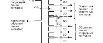
Parsing the circuit
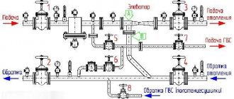
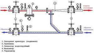
As you understand, the unit consists of filters, an elevator, instrumentation and fittings. If you plan to install this system yourself, then it’s worth understanding the diagram. A suitable example would be a high-rise building, in the basement of which there is always an elevator unit.
In the diagram, the system elements are marked with numbers:
1, 2 – these numbers indicate the supply and return pipelines that are installed in the heating plant.
3.4 – supply and return pipelines installed in the heating system of the building (in our case, this is a multi-storey building).
6 – this number indicates coarse filters, which are also known as mud filters.
The standard composition of this heating system includes control devices, mud traps, elevators and valves. Depending on the design and purpose, additional elements may be added to the unit.
Interesting! Today, in multi-storey and apartment buildings you can find elevator units that are equipped with an electric drive. This modernization is needed in order to adjust the nozzle diameter. Due to the electric drive, the thermal fluid can be adjusted.
Unit characteristics and operating features
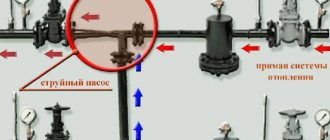
From the diagrams you can understand that the elevator in the system is needed to cool the overheated coolant. Some designs have an elevator, which can also heat water. This heating system is especially relevant in cold regions. The elevator in this system starts only when the cooled liquid is mixed with hot water coming from the supply pipe.
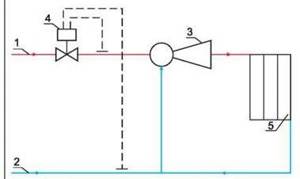
Scheme. The number “1” indicates the supply line of the heating network. 2 is the return line of the network. The number “3” indicates the elevator, 4 – flow regulator, 5 – local heating system.
From this diagram you can understand that the unit significantly increases the efficiency of the entire heating system in the house. It works simultaneously as a circulation pump and mixer. As for the cost, the unit will be quite cheap, especially the option that operates without electricity.
But any system also has disadvantages, the collector unit is no exception:
- Separate calculations are required for each element of the elevator.
- Compression drops should not exceed 0.8-2 bar.
- Lack of ability to control high temperature.
A little about the disadvantages
Despite the fact that the thermal unit has many advantages, it also has one significant drawback. The fact is that it is impossible to regulate the temperature of the exiting coolant using an elevator. If measuring the return water temperature shows that it is too hot, it will need to be lowered. This task can be accomplished only by reducing the diameter of the nozzle, however, this is not always possible due to design features.
Sometimes the thermal unit is equipped with an electric drive, with the help of which it is possible to adjust the diameter of the nozzle. It sets in motion the main part of the design - a cone-shaped throttle needle. This needle moves a specified distance into the hole along the internal cross-section of the nozzle. The depth of movement allows you to change the diameter of the nozzle and thereby control the temperature of the coolant.
Both a manual drive in the form of a handle and an electric remote-controlled motor can be installed on the shaft.
It is worth noting that the installation of such a unique temperature regulator allows you to modernize the overall heating system with a thermal unit without significant financial investments.
Possible problems
As a rule, most problems in the elevator unit arise for the following reasons:
- clogging in equipment;
- changes in the diameter of the nozzle as a result of equipment operation - an increase in the cross-section makes it more difficult to regulate the temperature;
- blockages in mud traps;
- failure of shut-off valves;
- regulator failures.
In most cases, finding out the cause of problems is quite simple, since they are immediately reflected in the temperature of the water in the circuit. If the temperature differences and deviations from the standards are insignificant, there is probably a gap or the nozzle cross-section has increased slightly.
A difference in temperature readings of more than 5 ℃ indicates the presence of a problem that can only be solved by specialists after diagnostics.
If, as a result of oxidation from constant contact with water or involuntary drilling, the cross-section of the nozzle increases, the balance of the entire system is disrupted. Such a flaw must be corrected as quickly as possible.
It is worth noting that in order to save money and use heating more efficiently, electricity meters can be installed at heating units. And hot water and heat meters make it possible to further reduce utility bills.
Heating system design
A thermal unit is a way to connect a home heating system to the main networks. The structure of the heating unit in a typical Soviet-era apartment building includes: a mud trap, shut-off valves, control devices, the elevator itself, etc.
The elevator unit is placed in a separate ITP room (individual heating point). There must certainly be shut-off valves in order to, if necessary, disconnect the intra-house system from the main heat supply. In order to avoid blockages and blockages in the system itself and in the devices of the internal house pipeline, it is necessary to isolate the dirt coming along with hot water from the main heating network; for this purpose, a mud trap is installed. The diameter of the mud trap is usually from 159 to 200 millimeters; all incoming dirt (solid particles, scale) collects and settles in it. The mud trap, in turn, needs timely and regular cleaning.
Control devices mean thermometers and pressure gauges that measure temperature and pressure in the elevator unit.
Adviсe
The selection of the necessary parameters for a heating system in an apartment building or private house (cottage) depends on the project and the money allocated to resolve this issue. Most often, the determining factors in this case are financial capabilities and local conditions.
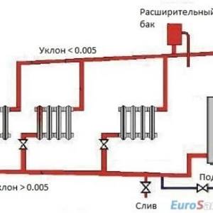
The gravity heating system is the simplest and cheapest. The heat source for such a system is a water boiler using wood, coal or natural gas. There is no pump in this system - convective circulation of water is provided by an expansion tank and pipe inclination.
The density of cold water is slightly greater than the density of hot water; the difference in density leads to the appearance of a slight excess pressure, which, together with the force of gravity, leads to the flow of coolant through the pipes of the system. The system is manually adjusted using valves and gate valves.
Semi-automatic system based on thermal heads and thermostats. System parameters are set manually, and subsequently they are maintained automatically. A system using microcontrollers and self-learning programs can operate completely autonomously for a long time. To analyze events in the system, a monitoring log is maintained. If you want to save as much as possible on the installation of a heating system by doing all the work yourself, but do not know how to use electric welding, you need to choose polypropylene pipes for the heating and hot water supply system. Installation of polypropylene pipes can be done using an ordinary wrench. These pipes are significantly cheaper than others. Installation errors can be quickly and cheaply corrected by re-installation. Welding polypropylene pipes on a machine can be easily mastered by a person who has never done this before.
Polypropylene pipes can be easily laid in hard-to-reach places. Their significant drawback is that to install a heating system you need a welding machine, which you will have to buy or rent. It is best to use polypropylene pipes with fiberglass reinforcement; they are much stronger and more durable.
By choosing metal-plastic pipes for the installation of a water heating system, you will be 100% confident in the reliability of the pipelines and the durability of the pipes laid in the cement screed of the “warm floor”.
Independent troubleshooting of the elevator unit:
- Clogged with garbage. Signs - after lightly tapping the body of the mud trap, cloudiness of the water or the appearance of a stagnant odor is observed. The mud trap needs to be washed.
- Corroded or clogged nozzle. Signs: a loud noise is heard, and the pressure in the system changes sharply during operation. The nozzle requires replacement.
- Clogged sump tank in the return line. Signs: pressure in the return line is increasing. The mud trap needs to be washed.
- Nozzle corrosion. Signs: different water temperatures on the floors. The nozzle needs to be replaced.
Thermal energy metering unit (heating): what is it? Scheme, installation
Constructing the correct installation project for the presented equipment is important for maintaining normal heating temperatures in each useful room of an apartment building without the need for residents to connect an autonomous heating system.
Regular checking of the data obtained from the described equipment allows you to eliminate possible shortcomings of the previously constructed heating circuit or its breakdown.
What is a thermal energy metering unit?
A thermal unit is a set of equipment, the installation of which is designed to provide fundamental accounting and regulation of energy, the volume of coolant, as well as registration and control of its parameters.
Thermal energy metering unit
Thermal energy metering unit is an automatic module, which is installed to the pipeline system to provide accounting data for the project of operation and regulation of heating resources.
Where are thermal units installed?
Installation of heating units and their maintenance are usually carried out in standard apartment buildings with communal heating systems.
In turn, thermal energy metering units are installed in an apartment building to perform the following tasks:
- checking and regulating the operation of coolant and thermal energy;
- checking and adjusting hydraulic and heating systems;
- recording fluid data such as temperature, pressure and volume.
- making a monetary settlement between the consumer and the heat energy supplier, after the received data has been verified.
Installation of heat metering units
When installing a heating equipment project, it should be taken into account that the consumption of resources supplied to the central heating in an apartment building incurs certain financial costs for the users (in this case, the residents of the apartment building).
An apartment building will be able to reduce costs, as well as maintain the functionality of the constructed unit according to the previously designed scheme for a long time, if competent checks of metering equipment and its maintenance, including high-quality installation of equipment and pipelines, are provided in a timely manner.
Design and diagram of the thermal unit
The heating unit, the installation of which is ensured according to a preliminary design in the communal systems of apartment buildings, is made from a whole complex of equipment and devices. Such a device is capable of performing one to several functions, such as:
- Measurement of the amount and mass of thermal energy, its pressure, temperature of the liquid circulating through the pipeline and operating time.
- Accumulation and storage of this information on local media.
- Display it on metering devices.
Based on the data obtained, the operation of heating equipment in apartment buildings is checked, its regulation and maintenance are carried out.
An accounting device is a device such as a meter, the circuit of which consists of:
- Resistance thermal converter.
- Heat calculator.
- Primary flow transducer.
Depending on which model of the primary converter was installed (with vortex, ultrasonic, electromagnetic or tachometer measurement options), the heat meter may include filters and pressure sensors.
Schematic diagram of the thermal unit
The thermal energy metering unit consists of the following elements:
- Shut-off valves.
- Heat meter.
- Thermal converter.
- Mudweed.
- Flow meter.
- Thermal sensor of the return pipeline.
- Additional equipment.
Installation of a thermal energy metering equipment circuit in an apartment building, in turn, implies the following fundamental requirements:
- the need to install the metering equipment circuit exclusively at the boundaries of the balance section of the pipelines in places closest to the main valves of the heating source;
- a ban on organizing a project for the selection of coolant for personal needs in the municipal heat supply system;
- regulation of the average hourly and average daily parameters of the coolant is carried out according to the readings of the metering equipment;
- metering devices are mounted on the return pipelines of the mains and placed up to the point of connection of the lining pipeline.
To carry out competent regulation and control of the described equipment, competent services carry out competent checks of their installation and operation.
Who installs and maintains the heating unit in apartment buildings?
In multi-apartment buildings, central heating (CH) and hot water supply (DHW) operate, the main supply pipeline for which is located in the basements, equipped with shut-off valves. The latter allows you to disconnect the in-house heating supply system from the external network.
The heating unit itself is equipped with mud traps, shut-off valves, instrumentation and has a device such as an elevator in its design. Of these, as a rule, the mud collector requires constant maintenance, which is a steel pipe with a diameter of DN = 159-200 mm and is necessary for collecting dirt coming from the main pipeline to protect pipelines and heating devices from contamination.
Installation of a thermal unit, its maintenance, including cleaning - the work of mechanics servicing a residential building, fulfilling the requirements of the organization providing housing and communal services.
Thermal energy metering unit (video)
Heating portal » Water heating
stroypotencial.ru