Uniform operation of the heating system and minimal time for its supervision is the dream of every owner of his own home. Last but not least is efficiency. The heat accumulator for heating (TA) combines and performs the above functions. This special device independently reduces or increases the temperature of the coolant at the right time. The result is thermal comfort in heated rooms. Human intervention in this process is excluded. How to connect a heat accumulator to a solid fuel boiler will be discussed below.
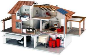
Heat accumulator for home heating system
Purpose of the heat accumulator
Installed in the heating system it is in automatic mode
:
- accumulates excess heat;
- releases the accumulated heat to the coolant at the right time;
- prevents water from boiling in the boiler in the absence of electricity;
- ensures boiler operation without human intervention.
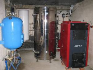
The buffer tank is designed to operate in automatic mode
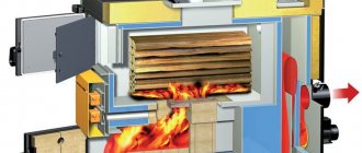
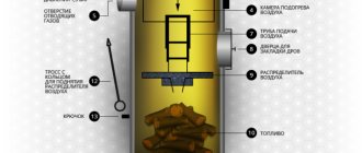
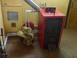
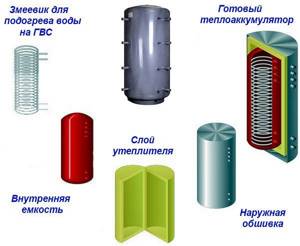
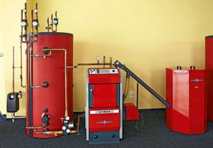
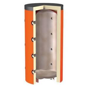
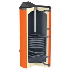
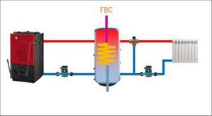
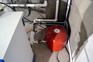
In a heat accumulator, excess heat is stored in a buffer tank for water. (Red in the photo). It is a water tank with a coil, covered with thermal insulation. While the wood is burning, it accumulates excess heat. As soon as the boiler stops producing the required temperature, excess heat from this tank is transferred to the heating system. The water in the radiators does not cool down. The heating system in houses is not installed without electric pumps that circulate the coolant. It is not difficult to imagine what happens during a power outage. The wood burns, heat is released, and the water stands motionless in the pipes. It begins to boil in the cauldron.
If this moment is missed, then an explosion with all the ensuing consequences is possible. The heating accumulator prevents this. While the fuel is burning, it must be added periodically. If you do not do this on time, the boiler will go out. Everyone knows how dangerous this is in severe frosts. Having TA, the process between adding firewood increases significantly. In this case, there is no danger of the system defrosting due to boiler attenuation.
Choosing a heat accumulator
TA is chosen when designing a heating system. Heating engineers will help you choose the right heat accumulator. But, if it is impossible to use their services, you will have to choose yourself. It's not difficult to do this.
Heat accumulator for solid fuel boiler
The main criteria when selecting this device are considered to be the following:
:
- heating system pressure;
- volume of buffer capacity;
- external dimensions and weight;
- equipping with additional heat exchangers;
- possibility of installing additional devices.
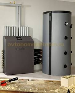
Water pressure (pressure) in the heating system is the main indicator. The higher it is, the warmer it is in the heated room. Taking this parameter into account, when choosing a heat accumulator for solid fuel boilers, attention is paid to the maximum pressure that it can withstand. The heat accumulator for a solid fuel boiler, shown in the photo, is made of stainless steel and can withstand high water pressure.
Buffer capacity volume. The ability to accumulate heat for the heating system during operation depends on it. The larger it is, the more heat will accumulate in the container. Here you need to take into account that raising the limit to infinity is pointless. But if there is less water than normal, the device simply will not perform its heat storage function. Therefore, to correctly select a heat accumulator, you will have to calculate its buffer capacity. A little later we will show how it is done.
External dimensions and weight. These are also important indicators when choosing a TA. Especially in an already built house. When the heat accumulator for heating has been calculated and delivered to the installation site, a problem may arise with the installation itself. In terms of overall dimensions, it may simply not fit into a standard door opening. In addition, large-capacity heating units (from 500 liters) are installed on a separate foundation. A massive device filled with water will become even heavier. These nuances need to be taken into account. But the way out is easy to find. In this case, two heat accumulators are purchased for solid fuel boilers with a total volume of buffer tanks equal to the calculated volume for the entire heating system.
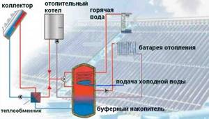
Equipped with additional heat exchangers. If the house does not have a hot water system or its own water heating circuit in the boiler, it is better to immediately purchase a heat exchanger with additional heat exchangers. For those living in the southern regions, it will be useful to connect a solar collector to the heat exchanger, which will become an additional free source of heat in the house. A simple calculation of the heating system will show how many additional heat exchangers it is desirable to have in the heat accumulator.
Possibility of installing additional devices. This implies the installation of heating elements (tubular electric heaters), instrumentation (control and measuring instruments), safety valves and other devices that ensure uninterrupted and safe operation of the buffer tank in the device. For example, in the event of an emergency extinguishing of the boiler, the temperature in the heating system will be maintained by heating elements. Depending on the volume of space heating, they may not create a comfortable temperature, but they will certainly prevent defrosting of the system. The presence of instrumentation will allow timely attention to possible problems that have arisen in the heating system.
Important. When choosing a heat accumulator for heating, pay attention to its thermal insulation. The preservation of the received heat depends on it.
Purpose of installation
Most often, experts recommend installing such devices in systems that provide heating using solar panels or electric furnaces. Both sources of heat production depend on the time of day.
Active operation of solar batteries occurs during the day, and an electric device is more efficient at night, since the cost of electricity at night is calculated at a low tariff, which means you can save money.
Taking into account such factors, it turns out that the buffer capacity at one time of the day works to accumulate heat, and at the second - to release it.
System efficiency
The storage tank is ideally combined with a gas-forming or solid fuel boiler. In this case, in addition to saving time and fuel, it acts as a security system. The highest degree of efficiency can be achieved by combining a buffer device with a gas generator.
Efficiency reaches its maximum under optimal fuel combustion conditions. Wood is converted into gas at a temperature of 400 degrees. With some change in parameters (pressure, temperature, fuel density in the combustion chamber of the boiler), the ratio of wood gas and oxygen becomes irrational, and the fuel goes into the chimney, significantly reducing the efficiency of the firebox and leading to an increase in wood consumption.
To improve efficiency indicators, the gas leaving the furnace must maintain the temperature at 90 - 120 degrees. At the same time, at this temperature, condensation forms in the pipe, and this threatens water entering the boiler with subsequent failure. Consequently, this combustion mode cannot be called optimal.
To improve the efficiency of the heater, it is necessary to provide it with a cyclic mode of operation in the form of several additions of fuel to the firebox with a maximum mode of energy production, which will be absorbed by the buffer tank. Then the boiler can be idle for several days.
Advantages
The duration of the furnace's sleep mode depends on the volume of the buffer tank (the volume must be selected taking into account the power of the heating device), from which energy is supplied during days of inactivity. With this heating mode, the following advantages can be noted:
- high level of efficiency of the heating boiler;
- minimizing fuel costs;
- development of a comfortable, stable temperature;
- reducing time spent on system maintenance.
Calculation of the volume of the boiler buffer tank
The most optimal solution to this task would be to entrust its implementation to heating engineers. Calculating the volume of a heat accumulator for the entire heating system of a private house requires taking into account various factors known only to them. Despite this, you can make preliminary calculations yourself. To do this, in addition to general knowledge of physics and mathematics, you will need a calculator and a blank sheet of paper.
We find the following data
:
- boiler power, kW;
- time of active fuel combustion;
- thermal power of heating the house, kW;
- boiler efficiency;
- temperatures in the supply and return pipes.
Let's look at an example of a preliminary calculation. Heated area – 200 m2, active burning time of the boiler – 8 hours, coolant temperature during heating – 90° C, in the return circuit – 40° C. The estimated thermal power of the heated rooms is 10 kW. With such initial data, the thermal device will receive 80 kW (10×8) of energy.
We calculate the buffer capacity of a solid fuel boiler based on the heat capacity of water
:
where: m – mass of water in the container (kg); Q – amount of heat (W); ∆t – difference in water temperature in the supply and return pipes (°C); 1.163 – specific heat capacity of water (W/kg °C).
Calculation of the buffer capacity of a solid fuel boiler
Substituting the numbers into the formula, we get 1375 kg of water or 1.4 m 3 (80000/1.163 × 50). Thus, for the heating system of a house with an area of 200 m2, it is necessary to install a heating unit with a capacity of 1.4 m3. Knowing this figure, you can safely go to the store and see which heat accumulator is acceptable.
Dimensions, price, equipment, manufacturer are already easily determined. By comparing known factors, it is not difficult to make a preliminary choice of a heat accumulator for your home. This calculation is relevant when the house is built and the heating system is already installed. The result of the calculation will show whether it is necessary to disassemble the doorways due to the dimensions of the TA. Having assessed the possibility of installing it in a permanent place, the final calculation of the heat accumulator for the solid fuel boiler installed in the system is made.
Volume calculation
Before you begin the calculations, you need to find out the average heat loss rate of the building. As an example, let's take a house with an area of 200 m². At an outside temperature of + 20 degrees, the heat loss of the building will be equal to 0. The lower the temperature outside, the greater the heat consumption becomes.
If at an air temperature of +15 degrees the heat loss is 2 kW/hour, then with each decrease by 5 degrees it will increase by 2 kW. These are averaged data, and for more accurate professional calculations it will be necessary to study several characteristics of the building (materials, insulation, climate zone).
To make up for the loss of thermal energy, it is necessary to install a heating boiler that can compensate for them and provide some energy reserve in case the temperature drops below the usual minimum. So, for frosts of 35 degrees, a 20 kW boiler will be enough.
It is worth remembering that in the case of solid fuel devices, it is quite difficult to control their power (wood either burns or does not).
Significant improvement cannot be achieved even by reducing the access of oxygen by closing the damper - the effect will be hardly noticeable.
The situation is no better with heating a house in the autumn-spring period, when the outside temperature is kept at 0 degrees and heat loss in the house does not exceed 8 kW, and the boiler performance is 15 kW.
In this case, more fuel is consumed than necessary, and 7 kW of energy is wasted, which is spent either on overheating of the radiators or on boiling in the system, which can lead to an emergency. For this purpose, a storage tank is installed, which absorbs excess power.
Connection methods
Connecting a heat accumulator to a solid fuel boiler is carried out in various ways.
But in any case, there are a number of rules that must be observed.
:
- all connections in the system must be threaded or flanged;
- It is recommended to install shut-off valves on the TA main;
- equipment of instrumentation and control equipment inputs and outputs;
- installation of cleaning filters at the entrances;
- installation of a pressure gauge and safety valve on the TA;
- provide for the installation of an air vent valve.
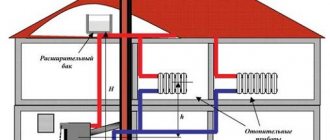
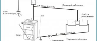
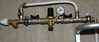
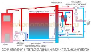
Plan for connecting a heat accumulator to a solid fuel boiler
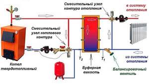
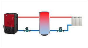
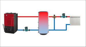
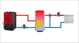
Compliance with these requirements ensures the functionality and safety of the entire heating system. Connecting a solid fuel boiler to a heat accumulator is carried out according to various schemes. The photo shows one of them. At its core, it is a simplified basic model of a heating system. Having understood the principle of its operation, you can begin installation yourself.
Watch the video to see how the strapping is done:
The boiler circuit mixing unit prevents cold water from entering the boiler. At the same time, a similar heating circuit unit, if necessary, supplies part of the hot coolant to the system to maintain the set temperature in it.
The balancing valve allows you to ensure equal heating of all heating devices, no matter how far from the boiler they are located. In the presence of additional coils and a solar collector on the roof, the TA turns into a thermal accumulator for a certain time. This allows you to reduce fuel consumption for the boiler. The connection diagram of the heat accumulator to the solid fuel boiler remains virtually unchanged.
Connection diagram of a heat accumulator to a solid fuel boiler
For your information. A heat accumulator for heating boilers can not only be connected, but also made with your own hands, which has already been tested by many.
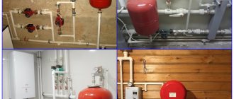
The heat accumulator for a solid fuel boiler allows you to burn fuel with maximum efficiency and increases the time between adding firewood. Along with noticeable fuel savings and a comfortable temperature in heated rooms, this device is becoming in demand in every heating system. Connecting a heat accumulator to a solid fuel boiler on your own does not create any great difficulties.
How to improve the efficiency of your heating system? In addition to standard methods, you can make a small modernization. It consists of installing additional tanks that can perform various functions. At the same time, it is important to choose the right capacity of the heating system: buffer, storage, storage. The efficiency and the possibility of organizing hot water supply will depend on this.
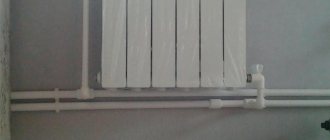
Buffer tank for heating
It is a barrel, inside of which there is a coil - it is connected to the heating main. The material of its manufacture is copper or steel. The energy from the coolant is transferred through the surface of the coil to the water in the container.
Design specifics
At first glance, the storage tank for heating does not have any particular advantages. However, upon in-depth analysis, it turns out that the relevance of its installation in an autonomous network is an undeniable factor. What functions does this design perform?
- Transfer of thermal energy to water, which can be used for hot water supply;
- Increased heating operation time even when the boiler is turned off. To do this, one of the pairs of pipes is connected to the system through two or three-way valves. In this case, the buffer tank of the heating system will mix the cooled coolant with the hot water remaining in it;
- The use of heated water for low-temperature heating circuits - water heated floors.
Such possibilities are explained by the design features. All factory buffer tanks for heating have additional insulation circuits. This minimizes the heat transfer of heated water. Also, the pipes have different diameters for connecting with heating circuits.
When choosing a factory model of a heating system tank (buffer, storage or storage), you need to pay attention to the number of pipes - from 2 to several dozen. Their optimal number depends on the circuits in the system.
Calculation of buffer capacity
Any heating system capacity is primarily characterized by volume. To calculate it, it is recommended to use special programs. If this is not possible, you can make approximate calculations yourself. The heat capacity of water is 4.187 kJ/kg*C. If the heating system has a rated power of 24 kW/hour, then the heating storage tank should maintain the system operation for 4-8 hours after the boiler is turned off. It is necessary to calculate the volume for an hourly heating operation. In this case, the temperature difference should be 70-45=25°C. Knowing that 1 kW/hour is 3600 kJ, we can calculate the capacity:
(24*3600)/(4.187*25)=825 kg or 0.825 m³
This is only an approximate calculation scheme, since each heating radiator tank has a number of additional characteristics - heat losses, temperature and humidity in the room, type of heating (gravity or forced circulation).
What should you consider when choosing a buffer tank for your heating system?
- Its useful volume;
- Area of the heat exchange element;
- The type of heat exchanger is a coil or a tank in a tank. The latter is preferable, since such a design increases the heating area of water in the container.
| Model | Peculiarities | Price, thousand rubles |
| Austria Email PSF 800 l. | Thermal insulation | 49,175 |
| Bosch BST 1000/80 Sr | Coil | 79,8 |
| Drazice NAD 1000 V1 | Without thermal insulation | 23,2 |
The price of a storage tank for heating is high - the simplest model for 800 costs from 35 thousand rubles, so they often try to make it themselves.
For heating a small private house, installing a tank of less than 500 liters is unprofitable. It will not be able to accumulate the required amount of thermal energy.
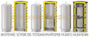
A variety of designs of buffer tanks and their connection diagrams
In this section of the publication, we will consider the design features of the main types of buffer tanks (they can vary significantly).
Main structural types of heat accumulators
| Illustration | Characteristic design features of the heat accumulator | Features of application |
| This is a buffer tank of the simplest design. It implements direct connection of both the boiler circuit and heating circuits, without the use of additional heat exchange devices. | The option is used in the following cases: - When the levels of permissible operating pressure in the heating circuits and the boiler circuit, as well as in the buffer tank itself, are equivalent; — When all circuits use the same coolant. (If the above requirements are not met, then the use of a buffer tank of this type is also allowed, but with the use of an external heat exchanger - this will be discussed below). — When the temperature regime of the boiler coincides with the maximum permissible temperature values in the heating circuits. (This condition can also be leveled by installing devices for high-quality regulation of their operating mode on heating radiators - special mixing units). |
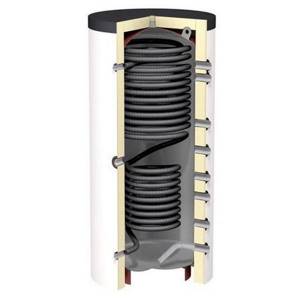
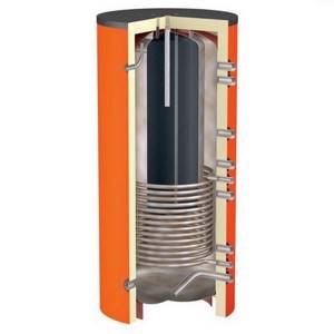
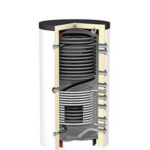
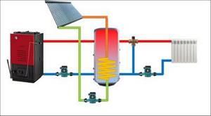
| An additional internal heat exchanger is located in the buffer tank. Usually this is a coil made of smooth or corrugated pipe. The number of heat exchangers may vary. The diagram additionally shows a magnesium anode rod (in the center), which serves to protect the surfaces of walls and heat exchangers from overgrowing with solid salts. The lower potential of the anode attracts ions of dissolved salts, and from time to time this element must be cleaned or replaced. | Typical cases of using the circuit: - When the correct operation of boiler equipment requires a pressure exceeding the operating parameters of the heating circuits or the heat accumulator itself. – When a circuit with several sources of thermal energy is used. (For example, solid fuel + electric boiler, boiler + solar collector or geothermal heat pump. In this case, the connection order is observed - the lower the thermal pressure the source has, the lower its heat exchange circuit should be located). – If, for technological reasons, different types of coolant are required in different circuits. This scheme is already characterized by active vertical mixing of the liquid, since the heat exchangers are located at the bottom, and the coolant heated from them, located in the buffer tank, tends to rise upward. |
| The scheme is similar to the first one, with direct connection of the circuits, but with an additional built-in heat exchanger for the hot water supply system. Cold water is supplied from below. Most of the heat exchange turns are usually concentrated in the upper part of the container. The heat exchanger is made of an alloy that meets sanitary standards for food water use. | The optimal use of such a scheme is when a stable consumption of hot water is established in the home lifestyle, without pronounced peak periods of consumption. |
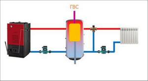
| A buffer tank in which the problem of hot water supply is solved by installing a storage tank - a kind of built-in indirect heating boiler. | This option will be preferable when the consumption of hot water in the house mainly occurs in large volumes, but over a short period of time. This design is capable of providing peak flow, but requires quite a lot of time for the built-in tank to fully heat back up. |
| In any of the previously given schemes, there can be multiple pairs of pipes spaced along the height of the buffer tank. | This design feature makes it possible to connect circuits that require different temperature pressures of the coolant, which ultimately greatly facilitates precise adjustments of the operating modes of each of them, with minimal loads on the control mixing devices. In any vertical container, a so-called temperature gradient arises, that is, a difference in the level of temperature pressure along the height. All that remains is to use this phenomenon correctly. |
Schematic diagrams for connecting buffer tanks
Now, in accordance with the considered features of the device, you can familiarize yourself with the most typical connection diagrams for buffer tanks.
| Simplified graphical representation of the connection diagram | Brief description of the connection diagram principle |
| When this scheme operates, the temperature and pressure parameters in the system are the same. Single type of coolant. The temperature in the boiler supply pipe and at the outlet of the buffer tank is maintained at the same level, and the final regulation of the heating system is carried out on the radiators by quantitatively changing the coolant circulating through them. |
| Despite the similarity with the first, this scheme is more rational and effective. Adjustment of operating modes of heating devices is already high-quality, that is, according to the principle of changing the temperature of the coolant at each of the heat exchange points. For these purposes, additional mixing units with a thermostatic operating principle are used. The accumulated thermal “charge” of the buffer capacity is spent much more economically, which, accordingly, expands the possibilities of its use over time. |
| This scheme has already been mentioned in the table above. In conditions where it is necessary to provide different pressures in the circuits of the boiler and heating system, or if there is a need to use different coolant compositions, circulation in the “small” circuit occurs through a heat exchanger coil built into the battery. |
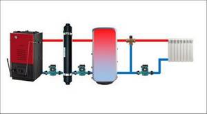
| This option is for the same conditions as in the previous case, but when for a number of reasons the scheme shown in the line above cannot be implemented. Options: - The contact area of the heat exchanger built into the buffer tank was not enough to effectively heat the coolant for the heating circuits. – In the general scheme, a heat accumulator of the simplest type is already installed, but modernization of the heating system leads to the need to separate the circuits of the boiler and radiators. In order not to purchase a new expensive buffer tank, it would be wiser to install an “intermediate link” - an external heat exchanger - between the small circuit and the heat accumulator. |
| An easy-to-implement scheme for organizing flow-through water heating for domestic use. The option is designed for uniform consumption, without pronounced massive intakes of hot water. |
| Buffer tank with built-in hot water tank. The situation is the opposite - such a scheme is more useful when the household water consumption pattern requires a one-time large volume of hot water, but then you will have to take a rather significant pause to fully heat the next “portion”. |
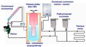
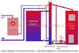
| A circuit in which two sources of thermal energy independent from each other are connected to a buffer tank. In the example shown, this is, in addition to the solid fuel boiler, a solar collector, although in its place there may be a second (including an electric) boiler. Depending on the equipment used and specific operating conditions, one of the sources becomes the main one, and the second either simply constantly “contributes to the piggy bank” of heat, or is turned on as needed, when it is necessary to “reheat” the volume of coolant. |
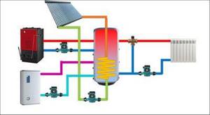
| Multivalent scheme, when three (maybe more) heat generators are used. In this case, a solid fuel boiler acts as a high-temperature source, which, again, can only act as a “back-up” to another, low-temperature source, for example, a heat pump (independent of either the season or the current running conditions) and a solar collector. The electric boiler shown in the diagram often plays a supporting role. The arrangement of the circuits is descending, from top to bottom, as their thermal pressure decreases. |
It is probably clear to everyone that the diagrams are presented in a very simplified form, only to clearly demonstrate the principle of operation. In practice, a heating system powered by a solid fuel boiler with connected other energy sources, incorporating a buffer tank, can be a very complex branched “organism” with an automated system for monitoring and adjusting operating modes. The design and installation of such systems is the job of highly professional specialists.
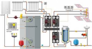
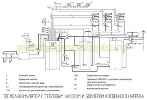
As an example, you can show the following hardware diagram:
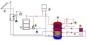
Multivalent scheme for heating and hot water supply at home
1 – main high-temperature heat source – solid fuel heating boiler.
2 – an additional electric boiler for heating, launched during the period of preferential electricity tariffs as needed.
3 – a special mixing unit is installed in the circuit of the main boiler, which ensures its rapid heating, without the negative effect of “cold return”.
4 – additional heat source – solar station with solar collector. In clear weather, it may well become the main source of heating.
5 – buffer tank (heat accumulator), connecting all sources of thermal energy and heating circuits into a single system.
6 – traditional heating circuit – high-temperature, with radiators or convectors, with quantitative adjustment of the heating level.
7 – low-temperature heating: water “warm floor” with its own mixing unit and high-quality regulation of the coolant temperature level.
8 – hot water supply circuit, flow type, with forced circulation and mixing unit - to maintain the specified water temperature in the DHW pipes.
By the way, an additional source of thermal energy can be located directly in the buffer tank itself. It is common practice to install electric heating elements in them, which, tied to thermostatic control equipment, are turned on only as needed. Sometimes such a measure allows you to once again avoid heating the boiler - the heating elements will make up for the current heat deficit.
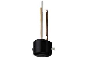
Built-in flange-type heating element with its own thermostat - perfect for additional installation in a buffer tank
You can purchase such heating elements yourself - in models specially designed for such purposes, the flange or coupling mounting system is adapted to the pipes of heat accumulators. In addition, some heating elements are already equipped with their own thermostatic regulator, that is, they do not require additional connection to external temperature sensors. They will turn on themselves when the temperature in the buffer tank drops below the set minimum limit.
Do-it-yourself heat accumulator
The difficulty in manufacturing buffer tanks for heating lies in creating reliable thermal insulation. For this, you cannot use a regular barrel or similar container. In addition to this parameter, the capacity of the heating radiator must withstand the load of water on the walls and possible water hammer.
The simplest design is a cube, inside of which there is a U-shaped pipeline or a coil made of copper pipe. The latter is preferable, since it has a large heat transfer surface area, and copper has an optimal thermal conductivity value. This structure is connected to a common highway. To make a heating system container, you will need steel sheets with a thickness of at least 1.5 mm and a metal pipe. Its diameter should be equal to the cross-section of the pipeline in this heating section.
The minimum set of tools includes the following:
- Welding machine;
- Angle grinder (grinder);
- Drill with drills for metal;
- Measuring tool.
The easiest way is to make a container for heating radiators in a cubic shape. A drawing is drawn up in advance, according to which all further work will be carried out. The presence of a heating element is not necessary, but preferable. It will be able to maintain the water heating level at the proper level.
The procedure for manufacturing a heat accumulator
First, rectangular sheets are cut out, which will make up the body of the heating system tank. At this stage, you need to take into account the gap for welding - it can be from 1 to 3 mm depending on the machine and the selected electrodes. Then holes are cut out in the blanks for attaching the pipeline, heating element and pipes for filling the container. Cast iron radiators cannot be attached directly to it. Therefore, it is necessary to calculate the heat losses from the tank to the radiator.
After assembling the structure, you need to insulate the body. For heating storage tanks, it is best to use basalt insulation. It has the following important qualities:
- Not flammable . Melting occurs at temperatures above 700°C;
- Easy to install . Basalt wool is quite elastic;
- Has vapor barrier properties . This is important for removing condensate, which will inevitably accumulate on the body of the storage tank during heating operation.
You can use an old steel tank as a container. But the thickness of its wall should not be less than 1.5 mm.
Installation of storage tank
The container is installed in front of the heating radiators. The best option is to connect the inlet pipe immediately after the boiler. According to this scheme, the water in it will be heated as quickly as possible.
To ensure maximum operational safety of the entire system, it is necessary to provide for the installation of the following components of the heating system tank piping:
- Shut-off valves on all pipes;
- Pressure gauges and thermometers. Temperature sensors must indicate the degree of heating of the water in the container and the coolant;
- Sets of 2-way valves for mixing heated water and coolant from the return pipe, so you can minimize energy costs.
Maintenance of the storage tank must be done before each heating season. It is best to disassemble it completely to remove scale and check the condition of the structure. If this is not possible, washing is done with special solutions.
The video describes the advantage of using a storage tank for an autonomous heating system:
- Content:
- What is buffer capacity
- Design and principle of operation
- Purpose of heat accumulators
- Pros and cons of buffer capacity
- Which heat accumulator to choose
- How to calculate buffer capacity
- Which company should I buy a buffer drive from?
The internal structure and operating principle of the heat accumulator for heating boilers is designed to ensure that the required coolant temperature is maintained for 5-10 hours after the main energy source is turned off. The storage tank is installed in connection with solid fuel and electric boilers. Connection to a heat pump and solar collectors is possible.
What is buffer capacity
Correctly used operating principle of a buffer storage tank in a heating system reduces heating costs and makes heating the building more comfortable. To ensure the feasibility of connecting a tank, it is necessary to consider its structure and operating principle, as well as take into account the existing advantages and disadvantages.
Design and principle of operation
The housing has an inspection window for servicing the tank, removing scale and debris, and carrying out repair work if necessary.
Purpose of heat accumulators
The basis of the operation of the buffer tank is due to the fact that excess thermal energy is accumulated, after which it is used to heat the building and hot water supply. A heat accumulator in a heating system is needed to maintain a comfortable temperature in a residential building after the main source of thermal energy is turned off.
The purpose of installing a storage tank varies depending on the type of heat generator:
Heat pumps are an indispensable operating condition; the inclusion of a buffer tank with a volume of 25 liters is included in the piping. per 1 kW of power. The purpose of use is somewhat different from that pursued when connecting the tank to electric and TT boilers. For the heat pump to operate properly, there must be sufficient heat when the evaporator defrost mode is activated.
Multivalent heating systems - the tank is used as a hydraulic separator of circuits of heating systems operating from several energy sources: solid fuel, gas and electric boilers, heat pumps connected to each other.
The tasks and purposes of using heat accumulators are different. In some cases, the installation of a tank is an indispensable condition of operation, in others it is just a desired requirement that ensures comfortable and economical heating of the building.
Pros and cons of buffer capacity
Now about the benefits of connection. There are several of them:
- Possibility of uninterrupted operation of solid fuel boilers - if a buffer tank is not installed in the heating system, the coolant begins to cool immediately after the firewood burns out. The drop in temperature is felt by a person after approximately 3 hours. When a heat accumulator is connected, cooling will occur more slowly. The water in the heating system will remain hot for about 5-10 hours (depending on the volume of the heat accumulator).
- Economical - excess thermal energy is accumulated and used when the coolant cools, which significantly reduces fuel costs.
- Safety - the operation of boilers with cast iron heat exchangers is simplified. After the tank, the water enters the boiler warm, which prevents damage to the core from rapid cooling.
- Additional functions - some tanks have a DHW coil. Simultaneous accumulation of the heated coolant and heating of hot water occurs. The installation can satisfy the domestic hot water needs of house residents who use single-circuit solid fuel or electric boilers that are not designed to provide hot water supply.
Technical specifications
Despite the obvious positive characteristics, the buffer tank still has a drawback - bulky dimensions. A small boiler room is unlikely to be able to accommodate the smallest container, a volume of 500 liters, the dimensions of which reach 1.8 m in height with a diameter of 0.6 m (the dimensions increase with insulation).
Such structures are difficult to squeeze into the door, which means that a considerable amount of space is needed for their installation. As practice shows, the area of the boiler room in which the buffer is installed must be at least 12 m².
Possible designs
Some experts suggest creating such containers directly at the installation site or using elastic materials in their production. It is worth noting that the storage tank can be of various shapes (in the form of a rectangle, cylinder, internal partition, stove bench, etc.).
You can also use it instead of radiators or heated floors. If you equip the tank with a coil, the problem of heating water for household needs will be solved. True, the cost of such devices will be rather high.
Which heat accumulator to choose
It is better to entrust the selection of storage capacity to specialists. You will need to select a tank that is optimally suited for the type of heating equipment used. The selection of a heat accumulator for a solid fuel boiler and a heat pump may differ. Leading manufacturers directly indicate in their operating instructions what type of heating system a particular buffer tank is intended for.
When choosing, pay attention to several technical characteristics:
- The material of the storage tank - a stainless steel tank - is unreasonably expensive, especially considering that the battery receives coolant from the heating system, which is less aggressive than water in the hot water supply. Enameled coating using glass polymers is the optimal solution.
- Additional functions - it is possible to select a tank for various water consumers, connect heating systems using water and special compounds as a coolant (heat pump, solar collectors). Tanks that are capable of heating water simultaneously with the accumulation of thermal energy deserve special mention.
The choice of heat accumulators begins with calculating the volume of the tank and determining the technical characteristics. After selection according to the parameters, the choice is made in accordance with the brand of the manufacturer you like.
How to calculate buffer capacity
To obtain the exact value, use the second method, using formulas for calculating the buffer capacity. During calculations, several values are calculated:
- battery accumulation time or water heating to a temperature of 80-90°C;
- battery life period;
- boiler power.
The method for calculating the buffer capacity includes the use of several formulas:
- Q = m × cp × (T2-T1) - according to calculations, it will be possible to calculate how long it will take to accumulate sufficient thermal energy and find out possible losses. Values:
- m—coolant flow rate;
- ср—specific heat capacity;
- T2 and T1 are the initial and final temperatures of heating water in the tank.
Using the formula, the heat accumulator for a solid fuel or electric boiler is calculated.
Solar collector area (m²)
Insolation 5 kW/m²
There is a third calculation method, in which the calculation of water in the battery tank is determined depending on the volume of water in the system, or more precisely on the rate of its heating. Usually the consumer knows how many times the boiler has to be fired with wood in order to maintain a comfortable temperature. When calculating, the volume of coolant is multiplied by the expected battery life between fuel refills.
And lastly, the capacity of the buffer tanks is selected so that 30-50 liters of coolant per 1 kW of boiler energy.
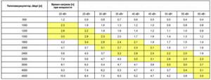
For convenience in calculations, you can use the following table:
Determination of the minimum amount of heat produced in kW is carried out using the tables attached below.
Calculations for electric boilers, subject to using a night tariff:
Area/time of independent work
The minimum required power to maintain a buffer tank connected to a solid fuel boiler in working order:
Area/time of independent work
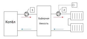
Principle of operation
Using a circulation pump, hot water leaves the boiler and enters the buffer tank. The same volume of cooled coolant is returned back. Next, from the upper part of the storage tank, with the help of a second pump, hot water goes to the radiators, from which the cooled liquid enters the lower part of the tank.
Pump No. 1 operates while the furnace is operating, and pump No. 2 is equipped with a thermostat that regulates the operation of the mechanism depending on the temperature in the room. Accordingly, the pump in the boiler works constantly, and the pump in the buffer tank turns on and off as necessary (lowering or increasing the temperature in the rooms).
For example, the pump powers are identical and they have the same performance. This means that all the thermal power (15 kW) from the buffer tank will go to the radiators.
If the heat loss of the house is 8 kW, then we will end up with overheating of the radiators, and the temperature in the house will rise, reach the maximum set on the thermostat (for example, 22 degrees) and pump No. 2 will turn off automatically. When the radiators cool down, the temperature in the room will also drop below the mark set on the thermostat, and pump No. 2 will begin to function again.
If we take into account that the performance of the pumps is the same, it will become clear that more hot coolant will enter the buffer tank than will be spent on circulation through the system and its temperature will increase. This is how heat is accumulated.
Heat transfer occurs in a certain order. When the boiler heats up and pump No. 1 turns off, heat stops flowing into the buffer tank. Pump No. 2 continues to function as usual and pumps out hot coolant from the tank, returning cooled water to its place, while the temperature in the tank drops.