Craving as a physical phenomenon
Before considering the design features of the firebox, you need to understand what vacuum in the firebox is. Vacuum or draft is a decrease in the pressure of combustion products, air, which ensures the flow of medium through the channels of a structure into a low-pressure zone. It is customary to distinguish between two types of draft: (See also: Do-it-yourself furnace firebox repair)
- natural - carried out under the influence of Archimedean force. In a furnace or boiler, air flows directly to the burner or grate. During combustion, hot air is generated. It is cooled partly due to the influx of new air, partly due to contact with the walls of the firebox. Hot air will rise up the pipe. The longer the pipe, the stronger the draft.
To control the process, you can close the hole through which new air enters. Very often, in small home boilers and furnaces, the natural draft is so good that it even requires reduction. The only drawback is that the higher the ambient temperature, the lower the vacuum. And also, if the regulation is poor, there will be so much cold air inside that the oven will not warm up;
- forced - using special mechanical devices. Usually, smoke exhausters - blade mechanisms, fans - are used to create it. The disadvantage of such a device is that the vacuum decreases as you move away from the mechanism, but the advantage is that by controlling the rotation speed, you can change the thrust.
(See also: Briquettes for heating stoves)
The smoke exhauster requires quite a lot of electricity and is noisy during operation. For small furnaces and boilers, it is better to choose options with fans. Usually, along with forced draft, natural draft will also be present in any system, but they are not always co-directed.
Main types of sensors
The main principle of operation of all sensors is signal conversion and interpretation of the result to promptly inform the user about changes in the operation of the gas boiler.
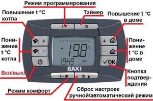
Gas equipment is equipped with a set of additional equipment, thanks to which it can be programmed for operation in a certain mode.
A compact overheat sensor extends the life of the gas boiler and prevents it from deteriorating due to high water temperatures
Key sensors responsible for equipment safety:
- traction;
- temperatures (outdoor and room);
- flame;
- pressure sensors (pressostat);
- overheating
Let's consider the characteristics and operating features of each of them.
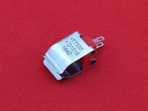
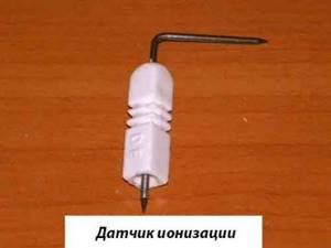
To determine the draft force, the device uses a draft sensor or a thermal relay for a gas boiler, which is also responsible for the correct combustion of gas.
Thanks to this small draft sensor, carbon monoxide will not enter the room, but will be discharged through the chimney to the street
Draft is necessary to rid the boiler of carbon monoxide. Normal draft “removes” combustion products from the room, and not into it; weak draft can provoke attenuation of the column and, as a result, an accident.
Most often, such sensors are installed in a smoke extractor. If the sensor breaks down, smoke from combustion products enters the room and poses a threat to life safety.
The type of sensor depends on the type of boiler you want to connect it to. The first type is boilers with natural draft, the second - with forced draft.
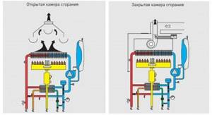
The diagram clearly shows the difference in the operation of open and closed combustion chambers in gas boilers, as well as in the chimney structure
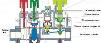
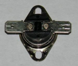
In devices with natural draft, the combustion chamber is open. During normal operation, carbon monoxide escapes through the chimney, and a safety thermostat monitors the presence of draft and the temperature of the flue gases. In such boilers, a sensor is used in the form of a metal plate with a contact attached to it.
The principle of its operation is to send a signal to the valve, which at the right moment will shut off the gas flow to the burner. Inside the thermostat there is a metal strip that reacts to changes in temperature.
The thermostat is adjusted to a certain temperature in accordance with the fuel in the boiler. If natural gas is used, then the temperature limits will be from +75 °C to +950 °C, in the case of liquefied gas - +75-+1500 °C.
If there is a malfunction in the process of carbon monoxide escaping (through the chimney to the street), in other words, the traction force is disrupted, then the device is triggered. When this happens, the temperature inside the apparatus rises, the metal expands, the sensor is triggered and the boiler cools down.
Owners of gas appliances with natural draft should pay attention to the concept of “reverse draft”. In simple words, this is a process in which carbon monoxide enters the room rather than being discharged into the chimney.
Failure occurs when temperatures fluctuate, incorrect installation of the chimney or its clogging, and inaccurate calculations of the dimensions of the chimney can also affect it. Regardless of the cause of backdraft, it must be eliminated immediately in order to avoid carbon monoxide poisoning.
Strong backdraft in action. It can provoke poisoning of residents of an apartment or house due to the large amount of carbon monoxide in the room
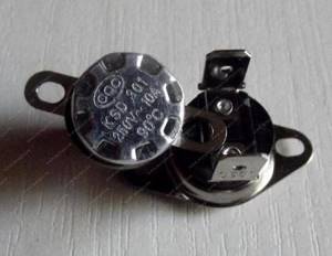
In devices with forced draft, a closed combustion chamber is installed and the gas is removed by a turbine-fan. A pneumatic relay sensor made in the form of a membrane is used here.
With normal draft, the membrane is slightly deformed under the force of carbon monoxide. When the flow becomes too weak and the membrane remains motionless, the contacts are disconnected and the gas valve closes. Such a sensor controls both the operation of the fan and the speed of combustion products.
If there is any doubt about the operation of the device that interrupts the gas supply in the event of a leak, it is advisable to install a carbon monoxide detector near the gas equipment. Its installation is strongly recommended, but not required.
Reasons for the draft sensor to be triggered: errors in the installation of the boiler or chimney, clogged chimney or fan stoppage (only in devices with forced draft).
The operating principle and design of the gas boiler automation system are described in detail in the following article, which we recommend that you read.
Operating principle of the pressure switch
A pressure switch or pressure sensor protects the boiler from overheating during a sudden change in gas pressure or a decrease in water flow.
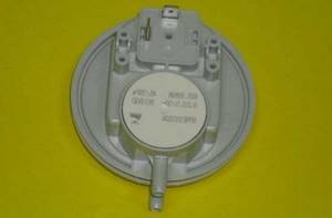
Installing a pressure switch protects gas equipment from sudden or too large pressure surges and, if necessary, turns off the gas equipment
Visually, this is a standard electrical sensor or relay, in most cases with two electrical corrector circuits. It is these circuits that determine the two key operating modes of the device:
- Mode 1 assumes normal pressure, during which the thermostatic membrane of the sensor does not change location and the first group of contacts closes. The boiler operates normally due to the passage of current through this circuit. It is also always connected to the general circuit of the unit.
- Mode 2 The mode is activated when some system parameter is out of normal range. Inside the relay, the thermostatic membrane shifts and bends. The first circuit of the controller is disconnected thanks to the membrane, and the second is closed. Boiler equipment stops working correctly. The operation of the standby mode, informing the boiler user about an emergency, is activated using the secondary circuit of the sensor.
The sensor is triggered even if there is the slightest increase in temperature in the combustion chamber. It monitors the minimum/maximum value of the pressure force, and also registers the beginning of moisture condensation in the combustion products or directly in the gas itself.
What does the overheat sensor monitor?
An overheating sensor is a small device that protects a gas boiler from boiling, which can occur when the temperature rises above +100 °C. When the limit temperature in the heating circuit is reached, the overheating sensor disconnects the contacts and turns off the gas appliance.
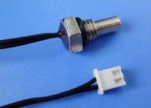
A special NTC (abbreviation for positive temperature coefficient) sensor is an immersion device. which controls the temperature inside the gas boiler
The device is based on either thermistors or biometric plates, sometimes these can be working NTC sensors.
Causes of gas boiler overheating and options for eliminating them:
- Lack of circulation in the heating circuit due to clogged filters. It is necessary to carefully clean all filters, rinse them or, if necessary, replace them with new ones.
- “Airing” of the heating circuit. You can get rid of it by simply removing the air.
- The duct is clogged due to a large layer of scale, and the boiler can be heard as if it is “knocking” or making popping noises. Remove excess in the device using special chemicals or acids.
- When starting the boiler, noise sounds are heard and the device may display an “insufficient circulation” error. A similar situation is possible when starting up the boiler, after its long-term downtime and without first running the ventilation system. The cause may be clogging in the pump due to inactivity. You need to disassemble the pump and wash it thoroughly, and then start it again.
- The equipment installation location was chosen incorrectly. In this case, if the air humidity or low temperature in the room is high, the metal from which the boiler is made will begin to quickly deteriorate.
For any reason of overheating, it must be removed immediately to avoid boiler breakdown or explosion. The user can get rid of overheating either independently or using the services of an experienced technician.
Outdoor and room temperature sensors
The main task of a temperature sensor for a gas boiler is to control the temperature and timely inform about its changes. Modern response devices operate on the principle of electrical resistance, which allows recording of operating readings.
According to the method of transmitting information, temperature sensors are:
- wired (connected to the controller using a cable);
- wireless (wireless radio communication is used to transmit the signal; such models consist of 2 parts).
Based on the type of control, they are divided into simple (maintain the temperature in the room) and programmable (there are many functions that allow you to influence the thermal conditions in the house).
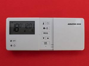
A complex programmable temperature sensor can be conveniently placed in a room and, using several buttons, regulate the temperature
Some sensor models have a built-in thermostat that allows you to control the humidity level in the room. There is also a function to reduce/increase humidity.
Depending on the placement method, the following devices are distinguished:
- overhead – attached to the heating circuit pipes;
- immersed - are in constant contact with the coolant.
In this case, indoor ones are located directly in the room, and outdoor ones are installed outside and react to temperature changes outside the window.
The first two types are used for coolant, i.e. for the boiler, and the second two are for controlling the air temperature. Overlays are mounted on the outer surface of the pipeline using a special tape or clamp.
Using a simple clip-on temperature sensor, the user can easily set comfortable temperature indicators, which the boiler will maintain
Submersible water heating sensors for the boiler are placed only in special places inside the device in close proximity to the coolant.
The response element for measuring temperature degrees can be an electrical transducer (thermocouple, resistance thermometer), pre-configured to a certain range. Such devices may have a display; some models have the ability to be calibrated in advance.
An outdoor temperature sensor allows the boiler to operate not all the time, but only when necessary. This increases the life of the gas boiler and the consumption of gas itself. When installing it, protection from mechanical and weather (moisture, frost) influences should be provided in advance.
The set of remote equipment includes:
- the sensor itself;
- terminals for clamping electrical cables;
- cable sleeve;
- a plastic case that will contain all the parts of the device.
When the temperature outside the window changes, the gas boiler sensor triggers a weather-dependent program that makes changes to the temperature regime for heating water for heating.
An outdoor temperature sensor is mounted on the outer wall of the room. When choosing it, you should check the device’s protective mechanisms in advance
The room sensor reacts to changes in temperature in the room, then sends information to the automation system, which controls the boiler. And it already gives a signal to reduce or increase the heating power of the heating circuit.
The principle of operation is that the user must initially set the required temperature in the room, and the equipment itself will control the gas equipment.
The boiler will be turned on only if the air temperature in the heated room is lower than the previously set one. This way, you will reduce your monthly gas bill by about a third.
A room temperature sensor will allow you to set the boundaries of a comfortable temperature regime, and then the equipment will maintain it in constant mode
When selecting a temperature sensor, pay special attention to the temperature range. The best option would be from – 10 °C to + 70 °C. Also consider the threshold temperature. There are models that respond to a decrease in temperature by 1/4 degree.
This is not very convenient, since the boiler will often turn off. However, most operate when the temperature changes by 0.5 or 1 degree.
The dimensions of the device itself are generally small: 2x3 cm. In wired models, the cable length must be at least 5 m. If wireless communication is used, be sure to test the radio signal.
The rules and nuances of adjusting the automation of gas heating equipment are described in detail in the article, the material of which is entirely devoted to this issue.
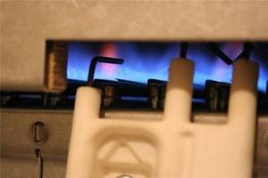
Flame sensor - reliable protection of your boiler
One of the key guarantees of safe operation for a gas boiler is the flame sensor. Its main task is to send a signal about the extinguishing of the flame on the burner to the automation system as quickly as possible to shut off the gas in order to prevent its leakage and explosion of the entire device. Also, this sensor should inform the controller about the quality of gas combustion, the presence of flame, and the intensity of combustion.
Types of flame sensors
They depend on the method of flame control when operating a gas boiler. Control can be direct or indirect. Thermometric, photoelectric, ultrasonic, ionization and are direct methods.
Indirect control is considered to be control over the formation of carbon monoxide in the firebox, over the fuel pressure in the pipeline through which it enters, over the pressure force or its fluctuations in front of the burner. This also includes checking for an inexhaustible source of ignition.
Based on the thermoelectric control method, the sensor includes a thermocouple (it includes a sensor and a solenoid valve). The thermocouple is placed in close proximity to the boiler burner, and the solenoid valve is mounted on the gas pipeline through which gas is supplied to the burner being ignited.
Connecting a flame sensor allows you to use a gas boiler or water heater at home without fear for your own life
Many modern devices install flame ionization sensors . Their operating principle is that when a flame burns, an ionization current occurs between the housing and the electrode of the sensor. It is formed in the event of attraction of ions. If there is no such current, then this becomes a signal to stop the gas supply.
If the combustion of the pilot flame produces the required amount of free electrons and negative ions, then the automation activates a key device that allows the operation of the main burner.
Please note that correct operation of the ionization sensor is only possible with an accurate phase connection of the heating boiler to the electrical network.
It is this mechanism that is much more effective than others in the case of gas combustion, since the gas does not actually produce light, so the photocell does not always react. The infrared radiation remains for a short time, which may be enough for a large amount of gas to accumulate, which automatically makes the infrared flame detector less safe.
The ionization sensor is mounted inside the boiler itself. It prevents accidents on gas equipment and protects the life and property of home or apartment owners
Photosensors monitor the flame of the key burner, but they are not used to diagnose the igniter flame due to the insufficient size of its flame. Such sensors are divided according to their response to the wavelength of the light flux: some respond to the visible and infrared spectrum of the light flux from a burning flame, while others “see” only its ultraviolet component.
To operate correctly, photocells must have “direct contact” with the burner flame, so they are mounted in close proximity to it. They are installed on the burner side at an angle to its axis of 20-30°. Because of this, photo sensors are susceptible to overheating by thermal radiation from the walls of the unit and heating through the viewing window.
In order to protect the photosensor from overheating, heat-resistant quartz glass and forced airflow are used, which is carried out either by low-pressure compressed air or by air produced by a fan.
The flame sensor may be triggered. when the key gas-air ratio is disrupted or the ignition device or valve becomes dirty. If the flame sensor breaks for any reason, it should be replaced immediately. This will save the life and health of you and your family.
Equipping gas heating equipment with a full set of safety sensors and automation devices does not eliminate the need for regular maintenance. How technical inspections and repairs of gas units are carried out is described in detail in the article we recommend.
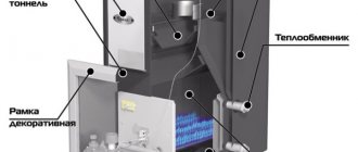
Firebox dimensions for excellent combustion
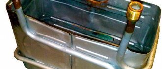
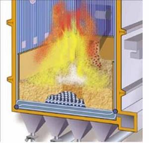
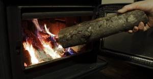
When laying out the stove yourself, you need to know how to properly arrange the firebox. This knowledge may also be required when choosing a firebox. The firebox is a rectangular chamber inside which fuel burns. There are always very high temperatures, and therefore special materials must be used. The standard dimensions are 25x38 cm. Height is about 80 cm. Most often, the chamber is used for burning wood, peat, and coal.
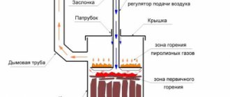
The design is such that the vacuum in the boiler furnace is uniform. The firebox has an obligatory part - a grate, as well as a blower. The grille is located slightly below the fuel door. It will contain firewood, peat, and flammable materials. There are holes made in it to ensure air flow. The vent is a hole in the stove below the firebox, which is needed to improve draft. The lower part of the firebox under the grate is the ash pit where waste will be collected. (See also: How to increase chimney draft)
There are three subtleties that determine the size of the furnace firebox:
- Creating maximum temperature. The higher the temperature in the firebox, the more productive the combustion will be. Temperature is very dependent on size. A wide firebox is bad because combustion products in the form of soot will quickly rise up and settle on the walls of the pipe, worsening draft, and it will not have time to warm up. Efficiency is calculated for both furnaces and boilers. Modern designs allow up to 90% for wood fireboxes. To reproduce such conditions, you need to make the firebox width approximately 25 cm, and the length required for the log. Typically the depth ranges from 50 to 63 cm.
- Using fire bricks for the interior of the firebox. It is easy to create a structure of any size from this material, and the material can withstand high temperatures well.
- Firebox height. It should be as high as the flame is possible. Typically, the flame from wood is higher than the flame from coal. If the stove is used as a stove, then the height of the firebox does not exceed 40 cm, and for heating the room it is better to choose 70 cm.
Regulating the vacuum in the boiler furnace - a modern approach
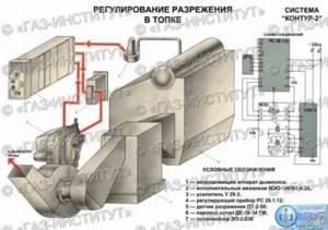
The article discusses the issue of constructing a system for automatic control of vacuum in the boiler furnace based on modern microprocessor automation tools using a frequency converter-inverter in the control loop. A method of gradual transition from the existing system to the proposed one is proposed.
The implementation of this system will significantly reduce the energy consumption for the drive of the smoke exhauster of the boiler unit, which operates most of the time in regulating mode.
This solution is proposed for implementation on boiler units of low and medium power.
Introduction
The government's calls for careful use of energy resources and the introduction of energy-saving technologies look at least strange for a country that has embarked on a market economy. A market economy based on fierce competition assumes this “default” approach. However, the Slav brothers, stubbornly adhering to the principle “until the thunder strikes,” are waiting in the wings. Finally, it came (“there would be no happiness:”).
Immediately there were calls for urgent action, summer seminars are already being organized in Yalta, etc. However, some solutions lie on the surface. As my long-time acquaintance, an inventor, said: “When I walk around the territory of the plant (workshop...), it seems to me that I am walking along banknotes.” Quick results in the field of heat power engineering can be achieved by paying due attention to the vacuum control circuit in the furnace of the boiler unit.
Even in the technical literature of 30 years ago, speed control was proposed as one of the possible ways to regulate the vacuum in the boiler furnace, either by changing the speed of the smoke exhauster using hydraulic couplings, or by changing the rotational speed of the electric drive. This method has been shown to be the most economical.
The appearance of frequency converters-inverters on the market created the conditions for the implementation of a long-standing technical idea.
1.1. Characteristics of the control section
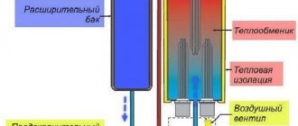
The object of vacuum regulation is a sequentially located furnace (combustion chamber) and gas ducts to the suction pipes of the smoke exhauster. There is a small vacuum of 2-3 mm. water Art.
(20-30 Pa) in the upper part of the combustion space is necessary for the stability of the torch in the combustion zone, to prevent the combustion products from being knocked out of the boiler and indirectly characterizes the material balance between the fuel oxidizer air and the exhaust gases-combustion products. The input control effect is the flow rate of the exhausted flue gases, determined by the performance of the exhaust fan.
An external disturbing influence is a change in the air flow supplied to the furnace when the thermal load of the boiler unit changes. Internal disturbances are violations of the gas-air regime.
The dynamic properties of the controlled object are characterized by the absence of delay, low inertia (time constant of the order of 5-10 seconds), and self-leveling. A special feature is fluctuations of the controlled value around the average value with an amplitude of 3-4 mm. water Art. (30-40 Pa) with a frequency of several hertz. Such low-frequency oscillations are caused, in particular, by pulsations of fuel and air consumption; in addition, the combustion process itself is a source of high-frequency oscillations (100-150 Hz), individual low-frequency modes of which can resonate.
1.2. Methods of regulation
The regulatory effect can be carried out by changing the performance of the smoke exhauster:
- changing the position of multi-axis throttle valves (curve 1 in Fig. 1);
- changing the position of the guide vanes (curve 2 in Fig. 1);
- speed regulation (curve 3 in Fig. 1);
It is clear from the graphs that at loads other than 100%, the most economical is the high-speed method of implementing the regulatory effect.
From the point of view of the structure of the control loop, the most widely used is a single-loop circuit with a pulse control unit, which, together with a constant speed actuator, implements the PI law in pulse mode.
However, it is worth noting that the control circuits for the fuel-air ratio and vacuum are physically connected through the control object, therefore, when the boiler operates in regulating mode (i.e., with frequent changes in the boiler load), a change in air flow to maintain the ratio with fuel upsets the balance of material flows and To prevent such a situation, a pre-emptive vanishing signal from the air regulator is introduced (real differentiation of the output signal of the air regulator).
1.3. Existing technical means of vacuum regulation
As a rule, the following automation equipment is used for low and medium power boilers:
- sensor - differential draft meter DT-2-50 (-100, -200, -300) produced by Moscow Thermal Automation Plant, Russia (MZTA);
- control unit RPIB (discontinued from MZTA), R25.1.2 (discontinued from MZTA), RS29.1.12 (MZTA) and its other models with differential. transformer input (available) or Ukrainian equivalent UKR01.1.12;
- actuator MEO-250/25-0.25-R-87 with a three-phase motor (there may be other models depending on the performance of the smoke exhauster) - manufactured by Cheboksary Actuator Mechanism Plant, Russia (ZEiM).
If it is necessary to carry out a dynamic connection between the fuel-air ratio and vacuum circuits, a dynamic connection kit KDS (MZTA) is used.
As you can see, the entire complex of technical equipment is produced in Russia. The viability of such a complex is due not only to the conservatism of the operators, but also to the presence of a powerful market of so-called “illiquid assets”, the life of which is predetermined.
Vacuum measurement
In boiler rooms, emergency situations are extremely undesirable, since a lot depends on them, and there may be casualties among the operating personnel. But even in a small house, the stove or boiler must work properly. Many sensors constantly monitor the operation of the device. There is a vacuum sensor in the firebox. There are several different sensor designs, the main thing is that it works properly.
The sensor can measure resolution, or react when a certain value is exceeded. In enterprises, the signal from the sensor is transmitted to a warning device: light, sound, electromagnetic. And employees or automation take measures to stabilize the situation. For example, the flow of air or fuel may be reduced. The measures taken depend on the design of the particular boiler or firebox.
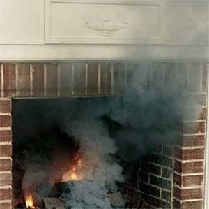
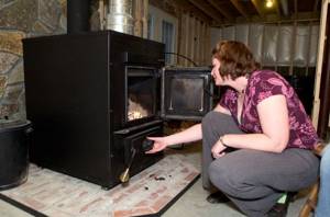
First firing of the furnace and checking the draft
After the stove has been folded, you need to do two things: let it dry and determine the quality of the draft. It will take a week for the oven to dry out. During this period, all doors and the oven vent are left open. You can burn paper and wood chips in small quantities. If you do not allow it to dry properly, the material may crack in the future.
To find out how much heat the stove will produce, a draft test is performed. It depends on:
- smoothness of the internal walls, including the walls of the firebox and chimney;
- pipe height - at least 5 meters. Usually they use the recommendation that the higher it is, the better.
Test fires are carried out slowly. First, they always burn paper and wood chips, and then they set fire to the wood. The room may become smoky. This indicates not very good traction. Sometimes burning paper or wood chips in the chimney solves the problem. A crimson flame indicates incomplete combustion of fuel. A lot of soot will form, settling in the chimney and narrowing the opening.
If the fire is straw-yellow in color and the smoke is colorless, then the stove is built correctly. You can check the traction using a special device. If it is not available, you can use plain paper. A sheet or strip of paper is carefully brought to the open firebox door. If it is deviated by the air flow towards the firebox and is drawn inward, then there is no problem. A well-built stove can be decorated with a mantel clock. It will not only heat the room, but also be aesthetically attractive.
Reasons for the drop in vacuum in the boiler furnace and ways to solve the problem
A drop below the minimum threshold of 9-10 Pa is considered critical; in this case, combustion problems may occur, unburned fuel and its combustion products may enter the room. If we exclude errors in the design of the combustion chamber and the boiler itself, the reasons for the drop in vacuum in the boiler furnace are usually simple and easily corrected:
- Chimney blockage. Both large objects entering the chimney from the street and natural soot formation, inherent not only in solid fuel, but also in any other (gas, liquid fuel, combined) boilers, can block the removal of combustion products, increase friction and narrow the diameter of the chimney. To fix the problem, you need to thoroughly clean the chimney of soot and ash using a metal brush on a long wire, any suitable scrapers, circles that practically correspond to the diameter of the chimney and other suitable tools. Even with normal technical condition of heating equipment and favorable operating conditions, it is recommended to carry out annual cleaning of the chimney before the start of the heating season.
- Problems with thermal insulation. Insufficient thermal insulation of the chimney or its absence leads to a strong decrease in the difference in the temperatures of the atmosphere and exhaust gases, which, accordingly, reduces the difference in air density (rarefaction).
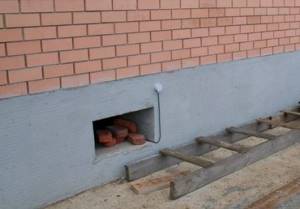
- Errors in chimney design. Most often, mistakes are made in determining the height of the chimney (the general and its street parts). To ensure normal draft, the total height of the chimney must be at least 5 meters. The standards for the roof ridge of a house are shown in the photo below.
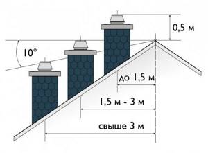
The optimal height of the chimney according to SNiP 41-01-2003. - Damage to the deflector. The deflector on the head of the chimney contributes to a more optimal direction of the flow of wind and exhaust gases; accordingly, if its design is violated, the properties are lost.
It is also important to understand that the vacuum may be unstable and insufficient if the temperature difference in the combustion chamber and the atmosphere is not so significant, for example, in relatively warm times outside the heating season when the boiler unit is operating at the minimum temperature.
From the META group
As many as four variants of fireplace inserts are produced by the META company:
- ARDENFIRE – META cast iron fireboxes, manufactured in France. This model has heat-resistant glass for monitoring the process. They have good heat dissipation and are durable. All connectors are additionally sealed with a special cord.
- EUROKAMIN - all models are assembled from parts manufactured in Europe. They are also equipped with special glasses. The stove is distinguished by good heat transfer and resistance to high temperatures.
- METAFIRE – inserts designed for fireplaces. The base is made of steel, the chamber is additionally lined with fire-resistant plates. The fireboxes in these models can be adjusted in height, and glass is also built-in. The price and quality of these models are well balanced.
- Caminetti is one of the new products. The cast iron firebox is lined with high quality steel on the inside. Has heat-resistant glass. It is characterized by rapid heating of the room, has small dimensions, and is aesthetically beautiful.
From Keddy
Swedish engineers are renowned for their ability to work with cast iron. Keddy fireboxes are distinguished primarily by the quality of the cast iron used. The technologies for its production and processing are classified. For a very long time they have mastered the intricacies of working with this material. For this reason, each of their products is distinguished by:
- high efficiency. Heating of the room begins the moment the fire is lit. In addition to cast iron, the design uses Olivi stone, which accumulates heat and releases it for a long time;
- reduced fuel consumption. The temperature will be maintained in the room for a long time without the need to frequently add fuel:
- durability. Any product will withstand more than one year of operation, the guarantee is up to 10 years.