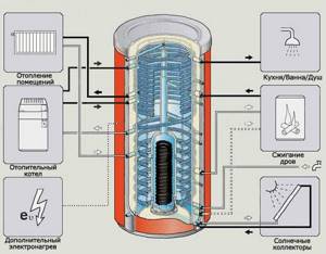
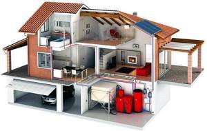
Operating principle of the device
Each heating device has its own special principle of operation.
Some boilers are characterized by a uniform operating mode (gas and electric heating equipment), others, on the contrary, are characterized by an unstable process. The heating intensity depends on the method of fuel supply and the presence of devices that control the combustion process. With appliances running on natural gas or electricity, everything is simple and clear. To regulate the heating temperature of the coolant, it is enough to reduce or even stop the gas supply and turn off the power supply. Constant power supply ensures uninterrupted operation of boiler equipment. Both day and night, the boiler operates in automatic mode, independently regulating the heating temperature of the coolant. Solid fuel boilers are units with high inertia. The fuel placed in the firebox burns constantly, and it is physically impossible to quickly stop this process. The thermal energy obtained during the combustion process should not be wasted. Excess heat is accumulated along with the coolant in a special container, which acts as a thermal energy accumulator.
The situation is similar with a decrease in the intensity of boiler operation. When the fuel mass is burned, the boiler sharply loses its performance, and the boiler water in the heating circuit begins to rapidly cool down. Without the next portion of fuel, there is a threat of a decrease in temperature in heated rooms. Of course there is a way out. A new supply of firewood or coal will solve the problem. Another question is how often you can carry out such a procedure, especially if the firebox is empty at night.
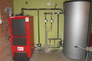
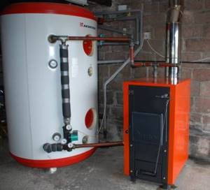
A solid fuel boiler connected to a buffer tank is a complex that can solve the problem of heating residential premises for you. Installing a buffer tank frees you from frequent and hard work of loading the combustion chamber of the heating device with another amount of firewood.
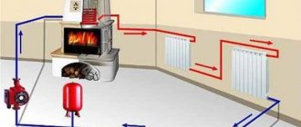
You can understand the principle of operation of a buffer tank using the example of a car battery. While the engine is turned on in the car, the electric current generator runs in parallel. The electricity generated by the generator is stored in the battery. When the main engines stop, the battery supplies the necessary energy back to the vehicle systems.
The buffer capacity works similarly. There is heat, the heat accumulator accumulates it, as soon as the heating installation stops producing heat, hot water from the storage tank is used to heat all heating systems.
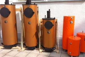
Top 10: types of heat accumulators for heating, features, price
The ten most popular heat accumulators for solid fuel boilers are as follows:
- Nibe BU – 500.8
- ETS 200
- HAJDU AQ PT 500
- HAJDU AQ PT 1000 C
- S-TANK HFWT -300 SERIES
- S-Tank AT 300
- S-TANK AT AT-1000
- HAJDU AQ PT 1000
- HAJDU PT 300
- S-TANK AT PRESTIGE -500
In retail, the price can vary from 55 to 200 thousand rubles. Many models of Belarusian and German manufacturers are presented in the form of steel tanks, without thermal insulation casing. The number on the label indicates the storage capacity.
Application of additional boilers
You can include a rather unusual element in the wiring diagram of a solid fuel boiler - an electric boiler. It cannot be called a harness, it is rather a simple duplicating addition. Such schemes are used when there is no space for placing a heat accumulator. The electric boiler works in tandem with a wood-burning unit, automatically turning on when a drop in temperature in the circuit is detected. Advantages of the scheme:
- Maintaining a stable heating temperature;
- There is no need to spend money on a tank - the simplest electric boiler costs only a few thousand rubles;
- Possibility of heating in the temporary absence of firewood;
- A restful night's sleep, since you don't have to jump out of your warm bed to throw the next batch of firewood into the insatiable firebox.
There are also disadvantages:
In addition, using a backup electric boiler is extremely ineffective if your area experiences frequent power outages.
- A backup electric boiler consumes a lot of electricity, which increases the cost of operating the heating system - this is not the most profitable scheme;
- To power a powerful boiler you will need a separate line and good electrical wiring;
- Particularly powerful models of electric boilers require connection to a three-phase network.
Therefore, investing in the purchase of a heat storage tank will be more profitable.
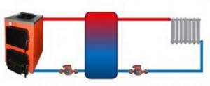
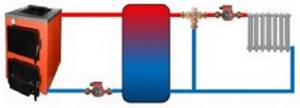
Simple switching circuit with mixing
The storage device can be connected to the system according to different schemes. The simplest connection of a solid fuel boiler with a heat accumulator is suitable for working with gravity coolant supply systems and will operate in the event of a power outage. To do this, the tank must be installed above the heating radiators. The circuit includes a circulation pump, a thermostatic three-way valve and a check valve. At the beginning of the heating cycle, water, driven by the pump, flows through the supply pipe from the heat source through the three-way valve to the heating devices. This continues until the supply temperature reaches a certain value, for example 60 ⁰C.
At this temperature, the valve begins to mix cold water into the system from the lower pipe of the tank, maintaining the set outlet temperature of 60 ⁰C. Through the upper pipe, directly connected to the boiler, heated water will begin to flow into the tank, and the battery will begin to charge. When the wood in the firebox is completely burned, the temperature in the supply pipe will begin to drop. When it drops below 60 ⁰C, the thermostat will gradually shut off the supply from the heat source and open the flow of water from the tank. That, in turn, will gradually be filled with cold water from the boiler and at the end of the cycle the three-way valve will return to its original position.
The check valve, connected in parallel to the three-way thermostat, comes into operation when the circulation pump stops. Then the boiler with the heat accumulator will work directly, the coolant will go to the heating devices directly from the tank, which will be replenished with water from the heat source. In this case, the thermostat does not take part in the operation of the circuit.
Solid fuel boilers and their connections
Some requirements for installing TT boilers
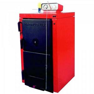
Solid fuel boiler Viadrus U22C-5
- The correct operation of the heating system depends, first of all, on the system itself, since it is possible to correctly connect a solid fuel boiler (with or without a water circuit) only if the installation of pipes and radiators is done professionally. After all, in fact, a water heating device of this type has only an input and an output, into which the rest of the circuit fits.
- In order for a solid fuel boiler to work with maximum efficiency and have the longest uninterrupted service life, the operating instructions suggest a minimum outlet temperature of 55⁰C, and an inlet (return) temperature of 45⁰C. Otherwise, condensation on the cold walls of the unit will reduce its temporary performance, destroying the metal. This can be avoided by using different schemes for connecting the boiler to the heating system.
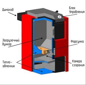
Pyrolysis boiler
- The installation of the unit is no less important, because the boiler must stand strictly vertically, on a rigid foundation, and this implies a cement screed of at least 5 cm thick with a bedding (half-layer) of the same thickness. The open type expansion tank must be located above the entire heating system and for this purpose it is most often placed in the attic.
- The boiler's chimney must be equipped with a stainless steel valve, and a condensate collection tank must be installed in its lower part. To be able to clean the channel from soot, small, easily accessible hatches can be made along its length. In the unheated part of the room through which the soot removal pipe passes, you should insulate it yourself to extend its service life.
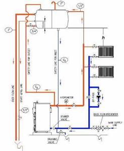
Connection diagrams for TT boilers
TT boiler connection
There are many schemes for connecting a solid fuel boiler, and all of them in one case or another are the most acceptable, and sometimes even irreplaceable. But, nevertheless, it is not at all necessary to memorize all the drawings in order to achieve the most optimal result - it is enough to know well the principle of operation of solid fuel units, their advantages and disadvantages.
The simplest and most popular connection diagram for a pyrolysis boiler
To calculate the ideal heating scheme, you need to combine the operation of a solid fuel unit with a thermal energy storage tank as best as possible. The fact is that the operating temperature of a water heating device constantly fluctuates around 60⁰C-90⁰C and it is almost impossible to keep it constant. After all, a boiler that runs on wood or coal is an inert device, unlike similar gas, electric and even diesel installations (you can see the connection diagram for a solid fuel boiler in this material).
Connecting a solid fuel boiler without forced circulation
It is not always possible to install a water pump for forced circulation of coolant and the reasons for this may be the most trivial. One of them is frequent voltage drops in the network, which are difficult to equalize with a stabilizer, or even the complete absence of power lines near the house. Of course, the price of such a system will be lower due to the lack of additional equipment, but its installation will require special care to maintain slopes.
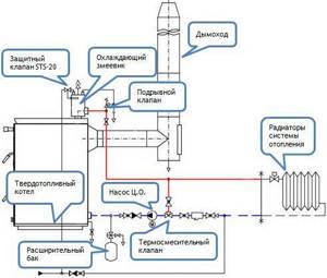
Another diagram for connecting a TT boiler to a heating system
Between the boiler and the tank in the heating system, it would be useful to have safety lines on the inlet and outlet pipes, as close as possible to the water heater
Also, the connection of the boiler to the expansion tank should take place in the shortest possible way, in which taps or safety valves cannot be cut in. Pay attention to the distance h in the diagram, which determines the rise of the expansion tank above the top point of the heating system. If for some reason it is impossible to lift the tank, so that the circulation pump should be cut into a straight pipe
Otherwise, you will open up the possibility of air being sucked into the upper radiators.
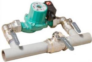
The principle of inserting a circulation pump
The circulation pump is installed on the return pipe near the heating boiler. This is done so that in the event of a power failure, the system continues to function without coercion. This unit is mounted along a bypass route and, if necessary, it can be disconnected from the network and the bypass can be closed with taps.
Homemade heat accumulator: advantages, design, connection diagram to the heating system
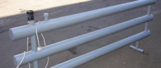
Among craftsmen, improving the heating system has recently become one of the most popular topics. The material used for the heat accumulator is 200 liter metal barrels, containers for technical fluids and even ready-made solutions - barrels from decommissioned fire trucks and army water-oil heaters. At the same time, the latter options are considered the most preferable - the containers already have thermal insulation and sufficient volume. So, from an AC-40 fire truck, the tank has a capacity of 1.5 tons, an army trailer holds 1 ton of water.
When designing, different calculation methods are used, but the fastest and easiest is to use an online calculator, into which you just need to substitute the requested indicators.
At the same time, despite the apparent simplicity of correctly calculating and installing a heat accumulator for a solid fuel boiler, it is also important to correctly select other equipment - pumps, valves, taps, electronic control devices.
Why is it needed?
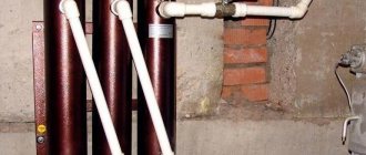
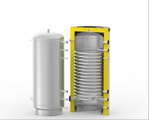
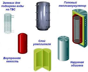
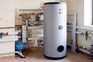
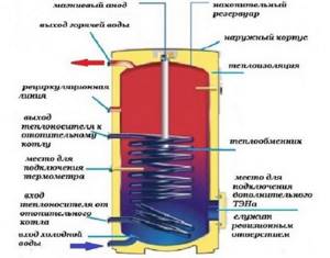
A buffer tank, also called a heat accumulator, is used in a heating system to accumulate and preserve heat. In appearance, this device resembles a cylindrical tank, has insulated walls, which allows you to maintain the temperature of the coolant for a long time. Heat-resistant foam rubber is used as thermal insulation.
According to experts, the heat accumulator is considered one of the main devices in the heating system. With its help, heat is distributed throughout all rooms of a country house or any other building. The main task of a buffer tank is considered to be the accumulation of heat, which can come from different devices, be it an electric or solid fuel boiler.
Heat accumulator device
The main element of the container is considered to be a heat-accumulating substance responsible for the preservation and further distribution of heat. The products in question can work:
- Steamed;
- Using liquid;
- With additional heating devices.
They can also be:
- Thermochemical;
- Solid state.
Most heating systems, including underfloor heating, use antifreeze, although it is best to use water for heating. Each of the buffer tanks has outlets for entering the boiler and heating pipes. A special valve is installed at the top of the container, protecting the device from excess pressure. Its main purpose is to remove accumulated air.
A drain valve is installed at the bottom of the tank to drain liquid if necessary. The tank has sockets for attaching sensors that indicate the pressure and temperature of the liquid.
The operation of the device in question is based on increasing the capacity of the coolant (water or antifreeze liquid - antifreeze). After fixing the tank, additional volume for liquid appears, as a result of which the inertia of the structure increases.
Note! When the buffer tank is heated by any heating device, a coolant of a certain temperature accumulates in the container. Heat distribution throughout the building occurs as the liquid cools, and thermal energy can be transferred even during the cessation of combustion processes in heating devices
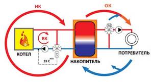
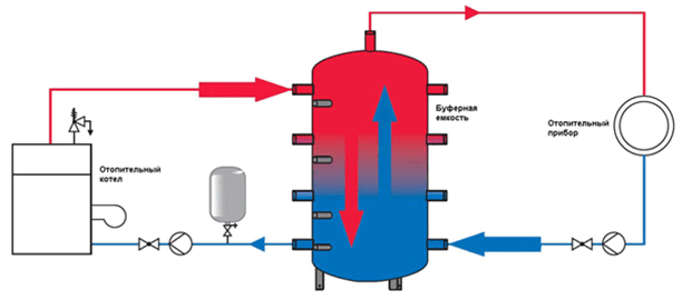
Let's consider the principle of operation of a heat accumulator using the example of a solid fuel boiler. In this case, a pump is installed between these two devices, which serves to distribute heat evenly in all rooms of the building. Cold water moves from the bottom of the tank to the boiler, where it is heated.
After heating, the coolant enters the upper storage part of the tank. When the pump, which is fixed in the return pipeline, operates, cold water from the system enters in small portions into the lower part of the tank, displacing hot liquid, which is sent to the heating system.
After the boiler is turned off, there is a continuous supply of heat. Note that this process continues until the cold coolant completely displaces the hot water from the tank. The duration of operation of the buffer tank after stopping the heating device (boiler) will depend on factors such as the volume of the tank, the air temperature outside the house, and the number of heating sources.
The principle of operation of the buffer tank
The main advantages of a buffer tank are:
- Uniform heat supply throughout the system. Most boilers heat the room unevenly, and this is due to the intensity of combustion or possible extinguishing of pallets, gas, or firewood. Using a buffer tank will avoid this phenomenon. During intense combustion, excess heat accumulates in the tank, which will be supplied to the system after the boiler dies out;
- Independence from the operating schedule of heating devices. The fact is that you need to constantly add firewood or other types of fuel to solid fuel boilers; doing this at night is inconvenient. Using a buffer tank will allow you to supply coolant at night using accumulated resources. In this case, the interval between firing the boiler increases. When using electric heating devices and having two tariff meters, you can program the boiler to operate at night;
- Protection against possible overheating;
- Fuel savings (up to 30% compared to a standard heating system).
Installation nuances
Thermal storage devices come in different sizes and designs.
But during installation for all categories it is necessary to comply with the same requirements:
- Welded joints are strictly prohibited when installing a heat accumulator;
- installation is carried out only with threaded couplings or flanges;
- it is necessary to equip all suitable pipelines with shut-off valves;
- install temperature sensors on all incoming and outgoing circuits;
- connect a drainage sensor to the system;
- “mud collectors” - install coarse filters at all inputs to the heat generator;
- Sometimes the heat accumulator package does not include an automatic air vent; it is necessary to purchase it and install it in the upper outlet circuit;
- It is recommended to install the safety group near the storage tank;
- it is necessary to place the heat accumulator only in a heated room to avoid freezing of the coolant;
- It is recommended to install the heating unit on a special foundation;
- To comply with safety regulations, place it so that there is free access to all incoming and outgoing circuits.
Connection diagrams for a solid fuel boiler
Let's look at various methods for connecting storage capacity.
The simplest and cheapest scheme to manufacture and operate consists of:
- heating unit;
- simple pipeline;
- ordinary buffer capacity;
- circulation pumps to move coolant from the heater to heat consumers.
The pressure throughout the system is the same. This scheme is suitable for small households.
A more rational use of the accumulated thermal energy is achieved by adding a mixing block to the heating circuit, which consists of a jumper that connects the supply and return pipelines and a three-way mixing valve with a thermal head.
This system has the ability to control and regulate the temperature of the coolant, while “charging the heat generator” lasts for a longer period.
To supply a residential building with hot water, thermal units of a more complex design are used.
Such devices include:
- heat exchanger consisting of spiral tubes made of stainless or corrugated steel;
- water heating tank;
- magnesium anode, which prevents the formation of scale on the inner walls of the tank, which must be changed periodically;
- thermal electric heating elements;
- thermometers - water sensors.
In this case, the supply pipeline is connected to the heat accumulator at the lowest point, and the outlet is mounted at the top.
Previously, schematic examples of heating were given.
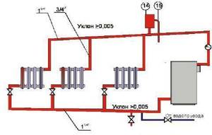
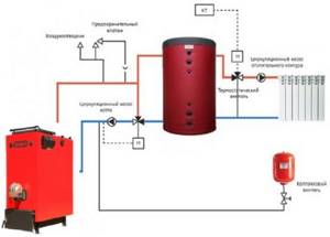
Let's take a closer look at the operating principle of the heating system and its composition:
- The heater is a solid fuel boiler.
- A security group immediately above the boiler, which monitors the temperature and pressure of the coolant in the system.
- The small heating circle consists of a jumper connecting the supply and return pipes, a three-way valve, a circulation pump and an expansion tank. The role of the small circle: protecting the heat generator from cold coolant and preventing the appearance of condensation in the boiler. At the beginning of the heat generator’s operation, water flows through the pipes partially into the heat generator and in a small circle. The coolant heats up to 60 degrees, the valve begins to work: it slowly opens and cold water from the return begins to mix with hot water from the small circuit. As soon as the temperature reaches 60 degrees, the valve completely closes the small circle and the coolant flows completely through the heat generator.
- The expansion tank takes excess pressure from the system and, if necessary, releases it back into it.
- Behind the small circuit, the supply pipeline is connected at the top point of the heat generator, and the return line is connected to the bottom point.
- After the tank, a three-way sensor with a room temperature meter and a circulation pump are again installed on the supply pipeline.
- Next are the heating radiators for the remaining rooms.
Connection diagram to the electric boiler
If the household has an electric meter with a two-phase “day-night” tariff, then an electric boiler can be used in tandem with a heat accumulator as the main source of heating. It will only work at night, heating the entire system and “charging” the thermal capacity to a temperature of 90 degrees. During the day, the heat source begins to release heat into the heating system. Using a circulation pump and temperature sensors, you can achieve uniform heat distribution in different rooms.
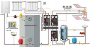
Another option for using electricity is found when operating a thermal accumulator: special thermal electric heaters are built into it.
They are used for additional heating of the battery at night or when there is no great need to heat the main heat source. If the design of the heating element does not include a temperature sensor, it is necessary to purchase and install one.
This article describes the main aspects of the design of heating systems, but when calculating and installing, if you do not trust your skills and skill, contact experienced specialists so as not to get into trouble later. Still, heating your home is a very responsible matter. Read about combined wood-electric heating boilers on our website.
About the specifics of the buffer tank in practice
Let's look at the diagram
Water heated by the boiler is supplied to the buffer tank using a circular pump 1. The same amount of water (but already cooled) is accordingly returned to the boiler. From the upper section of the buffer tank, pump 2 supplies hot water to the radiators. And the corresponding amount of cooled water is returned to the lower part of the buffer tank. Pump 1 operates while the boiler is burning. And the operation of pump 2 is regulated using a room thermostat: depending on the temperature in the room, it can turn the pump off or on.
Let's take a closer look at the mechanism for accumulating unclaimed power in a buffer tank. The boiler heats the water, in other words the thermal power, is transferred to the buffer tank. For example, let's take the figure of 15 kW from the situation described above. This power is transferred to the radiators using pump 2 (heat loss is compensated). Let's imagine that the performance level of both pumps is the same. In this case, the volume of thermal power,
which will enter the buffer tank will be equal to the volume that will enter the radiators (that is, designated 15 kW). But let us remember that it is early autumn in the yard, the temperature is 0°C, and the heat loss of the house is 8 kW. We transport too much heated water to radiators. What will happen? The temperature in the house will begin to increase, reach a comfortable temperature (indicated on the thermostat - for example, 20°C) and pump 2 will turn off. After a while, the radiators cool down, and the temperature in the room decreases. When the temperature in the house drops below that indicated on the thermostat, pump 2 will turn on and begin heating the radiators again. That is, as we have already noted, pump 1 operates constantly, and pump 2 alternates. Based on the fact that the performance is the same, but they work for different amounts of time, a larger volume of hot water enters the buffer tank than decreases. This means that the temperature in it will increase, and this is how heat accumulates.
Next, let's look at how the buffer tank releases accumulated heat. So, the boiler has worked and pump 1 is turned off - no more heat flows into the buffer tank. But pump 2 still functions as before: it pumps out hot water from the buffer tank and returns cold water. As a result, the temperature in the buffer tank decreases.
Popular models
It's time to understand the most popular models of heat accumulators for heating systems. We will consider products from domestic and foreign manufacturers.
Heat accumulator for heating boilers made in Russia Prometheus
The manufacturer of Prometheus heat accumulators is Novosibirsk. It produces models with volumes of 230, 300, 500, 750 and 1000 liters. The equipment warranty is 5 years. The heat accumulators are equipped with four outlets for connection to heating and heat sources. A layer of thermal insulation made of mineral wool is responsible for preserving the accumulated energy. The working pressure is 2 atm, the maximum is 6 atm. When purchasing equipment, take into account its dimensions - for example, the diameter of a 1000-liter model is 900 mm, which is why its body may not fit into standard doorways 80 cm wide.
The price of the presented heat accumulator for heating systems varies in the range from 65 to 70 thousand rubles.
SPSX-2G 1000
Another capacious heat accumulator for 1000 liters of water. It is equipped with one or two smooth-tube heat exchangers, but lacks thermal insulation, which must be taken into account when installing it - it will have to be purchased separately. The diameter of the case is 790 mm, but if thermal insulation is added to it, the diameter increases to 990 mm. The maximum temperature in the heating system is +110 degrees, in the DHW circuit – up to +95 degrees.
Buderus Logalux P 500-1000/5
These heat accumulators are available in modifications with six or ten connections. Temperature sensor terminals are also provided on board. The tank capacity is 960 liters, operating pressure is up to 3 bar. The thickness of the thermal insulation layer is 80 mm. The use of liquids other than water as a coolant is not allowed - this applies to both circuits, and not just the heating circuit. If necessary, it is possible to connect several heat accumulators in series into a single cascade.
Hydraulic split circuit
Another, more complex connection scheme involves an uninterrupted supply of electricity. If this cannot be ensured, then it is necessary to provide for connection to the network through an uninterruptible power supply. Another option is to use diesel or gasoline power plants. In the previous case, the connection of the heat accumulator to the solid fuel boiler was independent, that is, the system could operate separately from the tank. In this scheme, the battery acts as a buffer tank (hydraulic separator). A special mixing unit (LADDOMAT) is built into the primary circuit, through which water circulates when the boiler is ignited.
Block elements:
- circulation pump;
- three-way thermostatic valve;
- check valve;
- sump;
- Ball Valves;
- temperature control devices.
Differences from the previous scheme - all devices are assembled into one block, and the coolant goes into the tank, and not into the heating system. The operating principle of the stirring unit remains unchanged. This connection of a solid fuel boiler with a heat accumulator allows you to connect as many heating branches as you like at the outlet of the tank. For example, to power radiators and floor or air heating systems. Moreover, each branch has its own circulation pump. All circuits are separated hydraulically, excess heat from the source is accumulated in the tank and used when necessary.
Calculation of the volume of the boiler buffer tank
The most optimal solution to this task would be to entrust its implementation to heating engineers. Calculating the volume of a heat accumulator for the entire heating system of a private house requires taking into account various factors known only to them. Despite this, you can make preliminary calculations yourself. To do this, in addition to general knowledge of physics and mathematics, you will need a calculator and a blank sheet of paper.
We find the following data
:
- boiler power, kW;
- time of active fuel combustion;
- thermal power of heating the house, kW;
- boiler efficiency;
- temperatures in the supply and return pipes.
Let's look at an example of a preliminary calculation. Heated area - 200 m2, active burning time of the boiler - 8 hours, coolant temperature during heating - 90° C, in the return circuit - 40° C. The estimated thermal power of the heated rooms is 10 kW. With such initial data, the thermal device will receive 80 kW (10×8) of energy.
We calculate the buffer capacity of a solid fuel boiler based on the heat capacity of water
:
m=Q/1.163×∆t
where: m – mass of water in the container (kg); Q – amount of heat (W); ∆t – difference in temperature of water in the supply and return pipes (°C); 1.163 – specific heat capacity of water (W/kg °C) .
Substituting the numbers into the formula, we get 1375 kg of water or 1.4 m3 (80000/1.163×50). Thus, for the heating system of a house with an area of 200 m2, it is necessary to install a heating unit with a capacity of 1.4 m3. Knowing this figure, you can safely go to the store and see which heat accumulator is acceptable.
Dimensions, price, equipment, manufacturer are already easily determined. By comparing known factors, it is not difficult to make a preliminary choice of a heat accumulator for your home. This calculation is relevant when the house is built and the heating system is already installed. The result of the calculation will show whether it is necessary to disassemble the doorways due to the dimensions of the TA. Having assessed the possibility of installing it in a permanent place, the final calculation of the heat accumulator for the solid fuel boiler installed in the system is made.
Having collected data on the heating system, we perform calculations using the formula
:
W = m×c×∆t (1)
where: W is the amount of heat required to heat the coolant; m is the mass of water; c is the heat capacity; ∆t is the water heating temperature;
In addition, you will need the value k - boiler efficiency.
From formula (1) we find the mass:m = W/(c×∆t) (2)
Since the efficiency of the boiler is known, we refine formula (1) and obtain W = m×c×∆t×k (3) from where we find the updated mass of water m = W/(c×∆t×k) (4)
Let's look at how to calculate a heat accumulator for a home. The heating system is equipped with a 20 kW boiler (indicated in the passport data). The fuel fill burns out in 2.5 hours. To heat a house you need 8.5 kW/1 hour of energy. This means that during the burning time of one bookmark, 20 × 2.5 = 50 kW will be obtained
8.5 × 2.5 = 21.5 kW will be spent on space heating
The excess heat produced 50 – 21.5 = 28.5 kW is stored in the heat exchanger.
The temperature at which the coolant is heated is 35° C. (The difference in temperature in the supply and return pipes. Determined by measurements during operation of the heating system). Substituting the required values into formula (4) we obtain 28500/(0.8×1.163×35) = 874.5 kg
This figure means that to preserve the heat generated by the boiler, you need to have 875 kg of coolant. To do this, you will need a buffer tank for the entire system with a volume of 0.875 m3. Such simplified calculations make it easy to select a heat accumulator for heating boilers.
Heat accumulator calculation
To correctly calculate the required capacity of the heat accumulator, it is best to contact an experienced specialist. But at the same time, there are calculation methods by which you can approximately calculate the capacity of the buffer device in order to somehow figure out what power boiler to purchase, and determine the location of the heat storage device and the size of the boiler room.
There are two calculation methods:
- simple, based on the practice of specialists;
- according to the formula.
Based on many years of experience, experts have come to the conclusion that for 1 kW of boiler power, 25-50 liters of heat generator volume are needed. The truth is somewhere in the middle. If you install a smaller storage tank, the boiler will operate with less efficiency; if you install a larger volume, the house will be cold, since the heater will only accumulate heat, and there will not be enough of it in the system.
According to the formula, the capacity is calculated as follows: Q = mc (T2-T1), where:
- Q is the amount of accumulated heat,
- m is the volume of water in the container,
- c - specific heat capacity equal to 4200 J/(kg K),
- T2 and T1 are indicators of inlet and return water temperatures.
Application of buffer tank
The wiring diagram for a solid fuel boiler with a battery tank is not widely used. It is quite cumbersome, but allows for more correct heating operation. Its advantages:
- Stabilization of temperature in the system due to the increased volume of water in the circuit;
- Possibility of reducing the number of approaches for adding fuel to the boiler furnace due to the accumulation of excess heat in the storage tank;
- Possibility of accumulating clearly unnecessary excess thermal energy when using too powerful a boiler or excessive stacking of firewood.
The heat accumulator circuit has one drawback - it is necessary to allocate space for the device itself. The volume of the container used reaches several hundred liters, so you will need free space to place the tank.
There are many schemes for connecting buffer tanks. The simplest of them involve the use of the same coolant in the boiler and in the heating system. A more efficient scheme is using a three-way valve with a thermostat, which ensures a more uniform and economical consumption of thermal energy from the buffer tank.
Schemes with two circuits are also used. In this case, heat accumulators of heating systems are equipped with heat exchangers connected to solid fuel boilers. Heat exchangers heat the water in the tank, which is the coolant of the heating circuit. This option is distinguished by its efficiency and more uniform heating.
This scheme with a buffer tank is gentle for solid fuel boilers that are not designed for high heating pressure. And in this case, the coolants will be separated, the pressure in the tank and in the radiators will not in any way affect the pressure in the boiler itself and the heat exchanger.
Using a single-circuit solid fuel boiler often forces you to look for schemes for organizing hot water supply. For these purposes, you can adapt a storage or instantaneous water heater. It is also possible to use a more advanced heat storage tank with a built-in DHW circuit coil. This piping scheme will be an optimal and profitable solution, as it will solve the problem with hot water supply.
Selection of heat accumulator
The remaining criteria for choosing a container are not so important and mainly relate to different options. One of them is a built-in coil that heats water for household needs. It may be useful if there are no other means of heating, but for high costs in the DHW network this method is definitely not suitable. In addition, the heat exchanger will take away part of the “charge” of the heat accumulator, reducing the autonomous operation time of the heating.
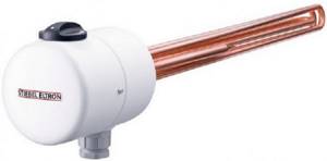
A useful option is a heating element built into the top of the tank, capable of maintaining the temperature of the coolant at a certain level. Thanks to electric heating, the system will not defrost in the event of an accident and will even be able to heat the house for some time after the battery has been “discharged” and the boiler has not yet been started.
The second coil for connecting the solar system is useful only in the southern regions, where solar activity will allow the heat accumulator to be loaded. But what you should pay attention to when selecting is the operating pressure of the tank. It should be taken into account that most solid fuel boilers are designed for pressure in the jacket up to 3 Bar, which means that the buffer tank should easily withstand the same amount.
Options for designs and their connection diagrams
Buffer tanks for heating systems can be rectangular or flat. But this measure is forced, determined by the installation conditions in a particular boiler room. Plain water or antifreeze can be used as a heat carrier.
To improve the efficiency of the container, it is recommended to insulate it with a layer of four to ten centimeters. In addition, the buffer tank for the heating boiler can be equipped with:
- built-in electric heating elements (heating elements);
- copper or steel coils made of stainless material or ferrous metal. Their main purpose is to prepare hot water supply, connect additional heat sources, solar systems, “warm floors”;
- tanks for preparing hot water with a capacity of one hundred to two hundred liters.
Now let's look at the most common options for connecting a buffer tank to a heating system.
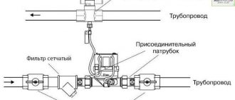
The main purpose of the mixing unit is to prevent cold water from returning to the heat generator. A three-way valve, adjusted to a temperature of at least forty-five degrees, directs the coolant in a small circle until it heats up to the set parameter. After this, cold liquid begins to flow through the valve in a dosed manner. To clean the system of scale, it is recommended to install a dirt filter upstream of the valve. It must be remembered that the vertical installation scheme is a mistaken action.
Most manufacturers strongly advise the use of heat accumulators (buffer tanks). This is due to certain reasons:
- after closing the damper, wood with a minimal amount of oxygen smolders in the chamber, which increases the amount of carbon monoxide and increases the level of environmental pollution. For this reason, the boiler must operate at average or maximum levels, concentrating excess heat in the container;
- as soon as the wood burns out, the thermal energy accumulated in the buffer zone will be enough to heat all the rooms for some time. The duration of this heating option depends on the size of the tank.
A connection option alternative to the previous method is to connect a solid fuel boiler with a buffer tank. The method of connecting the buffer tank to the heating system differs in that the tank does not accumulate heat, but separates the boiler from the pipe circuit of the heating system, of which there may be several, with different temperature conditions of the coolants.
Often, solid fuel boilers are installed as an additional element in houses that already have electrical installations. In order for joint work to proceed correctly, it is necessary to perform the correct piping, which provides for the units to secure each other. For example, coal burns out in a boiler. At this moment, the electric or gas boiler is automatically activated.
Connection diagrams
There are many ways to connect a solid fuel boiler with a heat accumulator and a heating system. But they are all derived from the basic circuit shown below. With its help, it is easy to understand how these units work in pairs, and then install everything yourself.
A heat source running on solid fuel has a traditional boiler circuit with a mixing unit, whose task is to prevent the supply of cold coolant to the boiler. Then the supply and return pipelines are connected to the buffer tank, respectively, from above and below. In the same way, a heating system, also equipped with a mixing unit, is connected to the heat accumulator. Its purpose is to maintain the required water temperature in the system, adding part of the hot coolant if necessary.
Important point. The actual performance of the boiler circuit circulation pump should be slightly higher than that of the heating network pumping unit. Compliance with this condition will allow the flows inside the heat accumulator to move in the right direction (shown in the diagram with white arrows).
In fact, the network pump will be more powerful than the boiler pump and here's why. The resistance of the network of pipelines and radiators is higher than 3-5 m of pipe from the solid fuel boiler to the heat accumulator. The unit needs higher power and pressure to overcome this resistance. Therefore, a weaker boiler circuit pump can provide higher flow rates, you just need to configure both units correctly. There are 2 options to resolve the issue:
- When using 3-speed pumps, you can adjust their performance by switching speeds.
- Place a balancing valve at the inlet of the return from the system into the buffer tank, which can be used to make adjustments.
Simultaneous heating of heating devices and layer-by-layer loading of a heat accumulator is possible when the flows inside the tank move horizontally with a slight predominance from the side of the solid fuel boiler. The question arises - how to check this? The answer arises: thermometers must be installed at both return inlets to the tank (as in the diagram) and adjustments must be made by switching pump speeds or rotating the balancing valve. Important condition: the three-way valve of the heating network must be fully opened manually.
By adjusting it is necessary to ensure that the temperature at the inlet to the heat accumulator (T1) is less than at its outlet (T2). This means that part of the hot water goes to “charging” the battery. You can learn more about all the points from an expert by watching the video:
Alternative scheme
This scheme for connecting a buffer tank and a solid fuel boiler was proposed by one of the participants in the popular forum. Its peculiarity is that in the event of a power outage, the operability of the circuit remains, although you have to pay for this with increased diameters of steel pipes. The figure below shows the connection of a heat accumulator to a closed heating system, but during installation it is better to make it open, as the author himself says.
Briefly, the essence is this: thanks to the T-shaped input on top of the tank, the radiators are simultaneously heated and the thermal accumulator, made by hand, is “charged”. The boiler circuit pump is controlled by a clip-on sensor on the supply line, turning on the unit when it reaches a temperature of 60 °C. The circulation in the network depends on the room thermostat to which the network pump is connected.
Note. The proposed strapping scheme was tested by its creator from his own experience. All details of its installation and operation are described by the author on the forum
How to choose the right heat accumulator for your heating system
Before installing the heating system, the type of main heat source is determined. The volume of the heat accumulator also depends on the power of the solid fuel boiler and the volume of tasks that the device will solve during operation. The size and capacity of the storage device is also determined by your household needs. When choosing a buffer tank, the priority when choosing a buffer tank is the model of the heating unit, which has a power limit and a limited time resource.
In other words:
when working in tandem with a solid fuel boiler, the buffer tank must ensure the accumulation of thermal energy during a one-time loading of fuel, sufficient to distribute hot coolant throughout the system until the subsequent loading of the combustion chamber.
Here it is appropriate to say a few words about the calculated data that influences the choice of the optimal volume of buffer capacity. Using calculations, it is possible to determine the real storage capacity of a specific volume of coolant, which affects the heat capacity.
To complete the picture, we count. When installing a heat accumulator with a volume of 1000 liters. (1000 kg), to heat water to a temperature of 50 0 C, the amount of thermal energy stored in the tank will be 1000 x 50 = 50,000 kcal or 58 thousand kW/h.
When hot water is consumed from the buffer tank and the water temperature decreases by 50 degrees, the amount of heat will correspondingly decrease by the same amount. Each connection diagram has its own method for calculating the capacity of a heat accumulator, however, there are the following general requirements that must be taken into account:
- the storage tank must be capable of accumulating the maximum amount of excess thermal energy during the combustion of fuel with a single load;
- the higher the peak thermal energy consumption in the heating circuit and the longer the maximum heat consumption, the larger the volume required for the buffer tank;
- if the boiler burns at a high intensity in short periods of time, it will be necessary to install an additional heat exchanger, either separately or integrated into the buffer tank;
- the drive must have a nominal pressure inside that is greater than at the point at which the device is connected to the system;
- in hot water storage tanks with two or more built-in heat exchangers, the system with lower operating pressure is connected to the lower heat exchange devices, and with high operating pressure, on the contrary, to the heat exchangers located at the top;
- installation of a heat accumulator requires the installation of an expansion tank and a safety, thermo-mixing valve in the system.
Diagram of a buffer tank-heat accumulator of a heating system, consisting of several tanks
Some craftsmen make themselves or outsource the production of buffer tanks from sections of large-diameter steel pipes - 300-800 mm. After installation in place, the tanks are insulated.
Such tanks are often much cheaper than ready-made buffer tanks that are sold on the construction market. The lack of corrosion protection in such homemade tanks is partially compensated by the increased thickness of the metal wall.
To protect against electrochemical corrosion, it is recommended to ground the tank and place a magnesium anode from an industrial water heater inside the tank.
A buffer tank of the required volume can be obtained by connecting two or more smaller tanks with pipes.
The upper and lower parts of the tanks are connected to each other by pipes with a diameter of at least one and a half inches.
It turns out to be a battery of tanks connected to each other like sections of a heating battery.
The battery from the tanks is connected to the boiler and heating circuits in a diagonal pattern. This connection ensures the same water temperature distribution in all buffer tanks.
The last tank in the battery (tank No. 2 in the diagram) can serve as a hydraulic separator between the radiator heating system and heated floors.
Final stage
The last steps before starting operation will be:
- Cleaning, priming and painting the inside of the tank. It should be primed and painted several times.
- Afterwards, pre-prepared coils (heat exchangers) are connected.
- The tightness and reliability of the structure is checked. This is done using pressurized water.
- The outside of the tank is painted.
- Thermal insulation material is installed. The outer casing made of galvanized steel sheet is mounted on pre-prepared fastenings.
If it is possible to entrust this matter to professionals or buy a factory buffer tank, it is better to do so.
Since its independent production requires extensive experience in welding and skills in thermal and hydraulic engineering. In addition, this will require a lot of resources, effort and time. Date: September 25, 2021