Heating mains, building heating systems, hydraulic circuits of machine tools, drainage systems, water pipelines - all these objects consist of pipelines. Engineering communications created on their basis are the most economical means of transporting various substances. Hydraulic calculation of pipelines allows you to determine the values of many characteristics at the maximum throughput of the pipe elements of the pipeline.

Hydraulic calculations are carried out for all systems - heating, water supply, sewer
Formulation of the problem
Hydraulic calculations when developing a pipeline project are aimed at determining the diameter of the pipe and the pressure drop of the carrier flow. This type of calculation is carried out taking into account the characteristics of the structural material used in the manufacture of the pipeline, the type and number of elements that make up the pipeline system (straight sections, connections, transitions, bends, etc.), productivity, physical and chemical properties of the working environment.
Many years of practical experience in operating pipeline systems have shown that pipes with a circular cross-section have certain advantages over pipelines with a cross-section of any other geometric shape:
- the minimum ratio of perimeter to cross-sectional area, i.e. with equal ability to ensure media consumption, the cost of insulating and protective materials in the manufacture of pipes with a cross-section in the form of a circle will be minimal;
- the round cross-section is most advantageous for moving a liquid or gaseous medium from the point of view of hydrodynamics; minimal friction of the carrier against the pipe walls is achieved;
- the circular cross-sectional shape is maximally resistant to external and internal stresses;
- The process of making round pipes is relatively simple and affordable.
The selection of pipes by diameter and material is carried out on the basis of specified design requirements for a specific technological process. Currently, pipeline elements are standardized and unified in diameter. The determining parameter when choosing a pipe diameter is the permissible operating pressure at which the pipeline will be operated.
The main parameters characterizing the pipeline are:
- conditional (nominal) diameter – DN;
- nominal pressure – PN;
- working permissible (excessive) pressure;
- pipeline material, linear expansion, thermal linear expansion;
- physical and chemical properties of the working environment;
- complete set of pipeline system (branches, connections, expansion compensation elements, etc.);
- pipeline insulation materials.
The nominal diameter (bore) of a pipeline ( DN) is a conventional dimensionless value that characterizes the flow capacity of a pipe, approximately equal to its internal diameter. This parameter is taken into account when adjusting related pipeline products (pipes, bends, fittings, etc.).
The nominal diameter can have values from 3 to 4000 and is designated: DN 80 .
The nominal diameter, by numerical definition, approximately corresponds to the actual diameter of certain sections of the pipeline. Numerically, it is chosen in such a way that the throughput of the pipe increases by 60-100% when moving from the previous nominal passage to the next. The nominal diameter is selected according to the value of the internal diameter of the pipeline. This is the value that is closest to the actual diameter of the pipe itself.
Nominal pressure (PN) is a dimensionless quantity characterizing the maximum pressure of the working medium in a pipe of a given diameter, at which long-term operation of the pipeline is possible at a temperature of 20°C.
The nominal pressure values have been established based on long-term practice and operating experience: from 1 to 6300.
The nominal pressure for a pipeline with given characteristics is determined by the pressure closest to the one actually created in it. At the same time, all pipeline fittings for a given main must correspond to the same pressure. The pipe wall thickness is calculated taking into account the nominal pressure value.
Examples of calculations
More often, speed is used to calculate water flow or pipe diameter. To do this, use the formula:
W= V×S, where W is the flow rate, V is the speed, S is the cross-sectional area of the selected pipes.
Using one of the tables, the speed of water movement is selected. If this is a fire water supply system, this parameter should be within 3 m/s. Quite a large value, but for a water supply system of this type the value is average, it can be even more.
For example, you need to calculate the cross-section of a pipe. To do this, you additionally need to decide how much water will be consumed through sprinklers or deluges of the fire protection system. This is also a tabular value depending on the protected area of the building or structure. Let it be a single jet fire system, in which the flow rate is usually 3.5 l/sec or 0.0035 m³/hour.
Knowing all the required parameters of the water supply system, you can calculate the cross-section of the pipes that will be installed in the network:
S=W/V=0.0035:3 = 0.0012 m².
Knowing the cross-section of the pipe, you can calculate its diameter. The area formula is: S=πD²/4, hence the diameter formula:
D=√4S/π=√(4×0.0012:3.14)=0.0038 m or 38 mm. There is no such pipe diameter value, so you need to choose the standard larger one - 40 mm.
This is the simplest example. In reality, most plumbing systems are complex schemes that contain bends, connected sections, installed shut-off valves and other obstacles that reduce the speed of water movement in the water supply system. At the same time, many networks have pumping stations installed that determine productivity and pressure. Often, a number of pumping units are installed in the system, which operate alternately: two, three, one at a time, in different sequences of switching on and off.
In such cases, the calculation is carried out in stages, for each section separately. In this case, additional coefficients must be taken into account, which level out the obtained values, as well as pressure losses at the fittings and at the installation sites of shut-off valves.
Basic principles of hydraulic calculation
The working medium (liquid, gas, steam) carried by the pipeline being designed, due to its special physical and chemical properties, determines the nature of the flow of the medium in this pipeline. One of the main indicators characterizing the working medium is dynamic viscosity, characterized by the coefficient of dynamic viscosity - μ.
Engineer-physicist Osborne Reynolds (Ireland), who studied the flow of various media, conducted a series of tests in 1880, as a result of which the concept of the Reynolds criterion (Re) was derived - a dimensionless quantity that describes the nature of fluid flow in a pipe. This criterion is calculated using the formula:
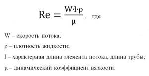
The Reynolds criterion (Re) gives the concept of the ratio of inertial forces to viscous friction forces in a fluid flow. The value of the criterion characterizes the change in the ratio of these forces, which, in turn, affects the nature of the carrier flow in the pipeline. It is customary to distinguish the following modes of liquid carrier flow in a pipe depending on the value of this criterion:
- laminar flow (Re<2300), in which the carrier-liquid moves in thin layers that practically do not mix with each other;
- transition mode (2300
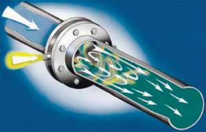
- turbulent flow (Re>4000) is a stable mode in which at each individual point of the flow there is a change in its direction and speed, which ultimately leads to equalization of the flow speed throughout the volume of the pipe.
The Reynolds criterion depends on the pressure with which the pump pumps the liquid, the viscosity of the media at operating temperature and the geometric dimensions of the pipe used (d, length). This criterion is a similarity parameter for fluid flow, therefore, using it, it is possible to simulate a real technological process on a reduced scale, which is convenient when conducting tests and experiments.
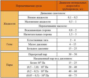
When carrying out calculations and calculations using equations, part of the given unknown quantities can be taken from special reference sources. Professor, Doctor of Technical Sciences F.A. Shevelev developed a number of tables for accurately calculating the pipe capacity. The tables include the values of parameters characterizing both the pipeline itself (dimensions, materials) and their relationship with the physical and chemical properties of the carrier. In addition, the literature provides a table of approximate values of the flow rates of liquid, steam, and gas in pipes of various sections.
Selection of the optimal pipeline diameter
Determining the optimal pipeline diameter is a complex production problem, the solution of which depends on a set of various interrelated conditions (technical and economic, characteristics of the working environment and pipeline material, technological parameters, etc.). For example, an increase in the speed of the pumped flow leads to a decrease in the diameter of the pipe that provides the media flow rate specified by the process conditions, which entails a reduction in material costs, cheaper installation and repair of the pipeline, etc. On the other hand, an increase in flow rate leads to a loss of pressure, which requires additional energy and financial costs for pumping a given volume of media.
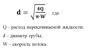
The value of the optimal pipeline diameter is calculated using the transformed flow continuity equation, taking into account the given media flow:
In hydraulic calculations, the flow rate of the pumped liquid is most often specified by the conditions of the problem. The flow rate of the pumped medium is determined based on the properties of the given medium and the corresponding reference data (see table).
The transformed flow continuity equation for calculating the working diameter of the pipe has the form:
Why does the speed have to be a certain value?
The speed of water in the pipes is taken into account when choosing the material and diameter of the pipeline.
If the speed is insufficient, undissolved particles that come with water from a well or well will be deposited on the walls of the pipes. This will lead to silting and a decrease in the flow area. As a result, the pressure and performance of the entire system as a whole will decrease.
If the water speed in the water supply is high, this leads to an increase in the pressure of the pumped liquid on the walls of the pipes and their joints. There is a good chance that a leak will occur somewhere in the pipeline over time.
Calculation of pressure drop and hydraulic resistance
Total fluid pressure losses include losses for the flow to overcome all obstacles: the presence of pumps, siphons, valves, elbows, bends, level differences when the flow flows through a pipeline located at an angle, etc. Losses due to local resistance due to the properties of the materials used are taken into account.
Another important factor influencing pressure loss is the friction of the moving flow against the walls of the pipeline, which is characterized by the coefficient of hydraulic resistance.
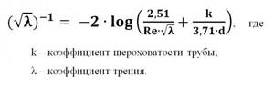
The value of the hydraulic resistance coefficient λ depends on the flow mode and the roughness of the pipeline wall material. Roughness refers to defects and unevenness of the inner surface of the pipe. It can be absolute and relative. The roughness varies in shape and is uneven across the surface area of the pipe. Therefore, the calculations use the concept of average roughness with a correction factor (k1). This characteristic for a particular pipeline depends on the material, the duration of its operation, the presence of various corrosion defects and other reasons. The values discussed above are for reference.
The quantitative relationship between the coefficient of friction, Reynolds number and roughness is determined by the Moody diagram.
To calculate the friction coefficient of turbulent flow motion, the Colebrook-White equation is also used, with the use of which it is possible to visually construct graphical dependencies by which the friction coefficient is determined:
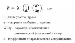
The calculations also use other equations for approximate calculation of friction head loss. One of the most convenient and frequently used in this case is the Darcy-Weisbach formula. Friction pressure losses are considered as a function of fluid velocity from the pipe resistance to fluid movement, expressed through the value of the surface roughness of the pipe walls:
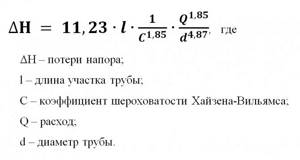
Pressure loss due to friction for water is calculated using the Hazen-Williams formula:
In a water heating system, many people especially often ask the question: How to calculate the diameter of the pipeline through which the coolant (water) will flow.
This material is designed to understand what diameter, flow rate and flow velocity are. And what are the connections between them. Other materials will contain detailed calculations of the diameter for heating.
In order to calculate the diameter you need to know:
Resistance to coolant movement.
Any coolant moving inside the pipe tends to stop its movement. The force that is applied to stop the movement of the coolant is the resistance force.
This resistance is called pressure loss. That is, a moving coolant through a pipe of a certain length loses pressure.
Head is measured in meters or pressure (Pa). For convenience, it is necessary to use meters in calculations.
Sorry, but I'm used to indicating pressure loss in meters. 10 meters of water column creates 0.1 MPa. In order to better understand the meaning of this material, I recommend following the solution to the problem.
Task 1.
Water flows in a pipe with an internal diameter of 12 mm at a speed of 1 m/s. Find the flow rate.
Solution:
You must use the above formulas:
| 1. Find the cross section 2. Find the flow rate |
Given:
| D=12mm=0.012 m p=3.14 |
S=3.14•0.0122/4=0.000113 m2
Q=0.000113•1=0.000113 m3/s = 0.4 m3/h.
Answer:
0.4 m3/h.
Task 2.
There is a pump that creates a constant flow of 40 liters per minute. A 1 meter long pipe is connected to the pump. Find the internal diameter of the pipe at a water speed of 6 m/s.
Of course, in reality, pumps do not produce a constant flow rate and do not produce an infinitely high pressure. Therefore, according to the conditions of the problem, we conventionally assumed that the pump pumps strictly 40 liters per minute, and the pump pressure is infinitely large. Below I will explain all the nuances of choosing the diameter.
Solution.
Given:
Q=40l/min=0.000666666 m3/s
From the above formulas I got the following formula.
Answer:
12mm
Unfortunately, using this formula to find the pipe diameter is not reasonable, and here’s why!
Each pump has the following flow-resistance characteristic:
This means that our flow rate at the end of the pipe will depend on the pressure loss that is created by the pipe itself.
| The longer the pipe, the greater the pressure loss. The smaller the diameter, the greater the pressure loss. The higher the coolant velocity in the pipe, the greater the pressure loss. Corners, turns, tees, narrowing and expansion of the pipe also increase pressure loss. |
This characteristic is actually not possessed by pumps, but by fluids that obey hydraulic laws. These laws apply not only to pumps, but also to all pipes through which liquid flows. Even if water flows out of a filled tank, such a flow-resistance characteristic will also be present there.
The pressure loss along the length of the pipeline is discussed in more detail in this article:
Pressure loss along the length of the pipeline.
Now let's look at a problem from a real example.
I would like to immediately notify you that these materials were used for the following task:
Professional calculation of pipe diameter for water supply.
Task 2:
The steel (iron) pipe is laid 376 meters long with an internal diameter of 100 mm; there are 21 bends along the length of the pipe (angular turns 90°C). The pipe is laid with a difference of 17 m. That is, the pipe goes up relative to the horizon to a height of 17 meters. Pump characteristics: Maximum head 50 meters (0.5 MPa), maximum flow 90 m3/h. Water temperature 16°C. Find the maximum possible flow rate at the end of the pipe.
Given:
| D=100 mm = 0.1m L=376m Geometric height=17m Bends 21 pcs Pump pressure=0.5 MPa (50 meters of water column) Maximum flow=90m3/h Water temperature 16°C. Steel iron pipe |
Find the maximum flow rate =?
Video solution:
Buy the program
To solve, you need to know the pump schedule: Dependence of flow on pressure.
I chose a visually similar graph of all pumps; it may differ from the real one by 10-20%. For a more accurate calculation, you need a pump schedule, which is indicated in the pump passport.
In our case, the graph will look like this:
Look, I marked 17 meters with a broken line along the horizon and at the intersection along the curve I get the maximum possible flow rate: Qmax.
According to the graph, I can safely say that due to the difference in height, we lose approximately: 14 m3/hour. (90-Qmax=14 m3/h).
There is no direct formula that gives a direct calculation of finding the flow rate, and if it does exist, then it has a stepwise nature and some logic that can confuse you - completely. The stepwise calculation is obtained because in the formula there is a quadratic feature of pressure loss in dynamics (motion).
Therefore, we solve the problem step by step.
Since we have a flow range from 0 to 76 m3/hour, I would like to check the pressure loss at a flow rate of 45 m3/hour.
Finding the speed of water movement
Q=45 m3/h = 0.0125 m3/sec.
V = (4•0.0125)/(3.14•0.1•0.1)=1.59 m/s
Finding the Reynolds number
ν=1.16•10-6=0.00000116. Taken from the table. For water at a temperature of 16°C.
Re=(V•D)/ν=(1.59•0.1)/0.00000116=137069
Δe=0.1mm=0.0001m. Taken from the table for a steel (iron) pipe.
Next, we check the table, where we find the formula for finding the coefficient of hydraulic friction.
I get it in the second area, provided
10•D/Δe
10•0,1/0,0001
10 000
λ=0.11(Δe/D + 68/Re)0.25=0.11•(0.0001/0.1 + 68/137069)0.25=0.0216
Next we finish with the formula:
h=λ•(L•V2)/(D•2•g)= 0.0216•(376•1.59•1.59)/(0.1•2•9.81)=10.46 m .
As you can see, the loss is 10 meters. Next, we determine Q1, see the graph:
Now we make the original calculation at a flow rate of 64 m3/hour
Q=64 m3/h = 0.018 m3/sec.
V = (4•0.018)/(3.14•0.1•0.1)=2.29 m/s
Re=(V•D)/ν=(2.29•0.1)/0.00000116=197414
λ=0.11(Δe/D + 68/Re)0.25=0.11•(0.0001/0.1 + 68/197414)0.25=0.021
h=λ•(L•V2)/(D•2•g)= 0.021•(376•2.29 •2.29)/(0.1•2•9.81)=21.1 m.
We mark on the graph:
Qmax is at the intersection of the curve between Q1 and Q2 (Exactly the middle of the curve).
Answer: The maximum flow rate is 54 m3/h. But we solved this without resistance when cornering.
To check, let's check:
Q=54 m3/h = 0.015 m3/sec.
V = (4•0.015)/(3.14•0.1•0.1)=1.91 m/s
Re=(V•D)/ν=(1.91•0.1)/0.00000116=164655
λ=0.11(Δe/D + 68/Re)0.25=0.11•(0.0001/0.1 + 68/164655)0.25=0.0213
h=λ•(L•V2)/(D•2•g)= 0.0213•(376•1.91•1.91)/(0.1•2•9.81)=14.89 m .
Result: We got to Npot=14.89=15m.
Now let’s calculate the cornering resistance:
Formula for finding pressure on local hydraulic resistance:
Read more about this in the section: Local hydraulic resistance
| h-pressure loss here it is measured in meters. ζ is the resistance coefficient. For a knee it is approximately one if the diameter is less than 30mm. V is the velocity of fluid flow. Measured [Meter/second]. g-gravitational acceleration is 9.81 m/s2 |
ζ is the resistance coefficient. For a knee it is approximately one if the diameter is less than 30mm. For larger diameters it decreases. This is due to the fact that the influence of the speed of water movement relative to the turn is reduced.
I looked in different books on local resistances for turning pipes and bends. And he often came to the calculation that one strong sharp turn is equal to a coefficient of one. A sharp turn is considered if the radius of the turn does not exceed the diameter. If the radius exceeds the diameter by 2-3 times, then the coefficient value decreases significantly.
Read more about this in the section: Local hydraulic resistance
Let's take ζ = 1.
Speed 1.91 m/s
h=ζ•(V2)/2•9.81=(1•1.912)/( 2•9.81)=0.18 m.
We multiply this value by the number of bends and get 0.18•21=3.78 m.
Answer: at a speed of 1.91 m/s, we obtain a pressure loss of 3.78 meters.
Let's now solve the whole problem with taps.
At a flow rate of 45 m3/hour, we obtained a pressure loss along the length: 10.46 m. See above.
At this speed (2.29 m/s) we find the cornering resistance:
h=ζ•(V2)/2•9.81=(1•2.292)/(2•9.81)=0.27 m. multiply by 21 = 5.67 m.
We add up the pressure loss: 10.46 + 5.67 = 16.13 m.
We mark on the graph:
We solve the same thing only for a flow rate of 55 m3/h
Q=55 m3/h = 0.015 m3/sec.
V = (4•0.015)/(3.14•0.1•0.1)=1.91 m/s
Re=(V*D)/ν=(1.91 •0.1)/0.00000116=164655
λ=0.11(Δe/D + 68/Re)0.25=0.11•(0.0001/0.1 + 68/164655)0.25=0.0213
h=λ•(L•V2)/(D•2•g)= 0.0213•(376•1.91•1.91)/(0.1•2•9.81)=14.89 m .
h=ζ•(V2)/2•9.81=(1•1.912)/( 2•9.81)=0.18 m. multiply by 21 = 3.78 m.
Add up the losses: 14.89+3.78=18.67 m
We draw on the graph:
Answer:
Maximum flow=52 m3/hour. Without branches Qmax=54 m3/hour.
To avoid doing all the math manually, I prepared a special program:
Now I think you understand how resistance to flow occurs. If it is not clear, then I am ready to hear your comments on this article. Write comments.
As a result, the diameter size is affected by:
| 1. Resistance created by a pipe with turns 2. Required flow 3. Influence of the pump by its flow-pressure characteristic |
If the flow rate at the end of the pipe is less, then it is necessary to: Either increase the diameter or increase the pump power. Increasing pump power is not economical.
Calculate the diameter of the heating pipe
This article is part of the system: Water heating designer
| Like |
| Share |
| Comments (+) [ Read / Add ] |
All about the country house Water supply Training course. Automatic water supply with your own hands. For Dummies. Malfunctions of the well automatic water supply system. Water wells Well repair? Find out if you need it! Where to drill a well - outside or inside? In what cases does cleaning a well make no sense Why pumps get stuck in wells and how to prevent it Laying a pipeline from a well to a house 100% Protecting the pump from dry running Heating Training course. Do-it-yourself water heated floor. For Dummies. Warm water floor under laminate Educational Video course: According to HYDRAULIC AND THERMAL CALCULATIONS Water heating Types of heating Heating systems Heating equipment, heating batteries Heated floor system Personal article on heated floors Operating principle and operating diagram of a heated water floor Design and installation of a heated floor Do-it-yourself water heated floor Basics materials for heated water floors Installation technology of water heated floors System of heated floors Laying step and methods of laying heated floors Types of water heated floors All about coolants Antifreeze or water? Types of coolants (antifreeze for heating) Antifreeze for heating How to properly dilute antifreeze for the heating system? Detection and consequences of coolant leaks How to choose the right heating boiler Heat pump Features of a heat pump Heat pump operating principle About heating radiators Methods of connecting radiators. Properties and parameters. How to calculate the number of radiator sections? Calculation of thermal power and number of radiators Types of radiators and their features Autonomous water supply Scheme of autonomous water supply Construction of a well Cleaning a well with your own hands Experience of a plumber Connecting a washing machine Useful materials Water pressure reducer Hydraulic accumulator. Operating principle, purpose and configuration. Automatic air release valve Balancing valve Bypass valve Three-way valve Three-way valve with ESBE servo drive Thermostat for radiator Manifold servo drive. Selection and connection rules. Types of water filters. How to choose a water filter for water. Reverse osmosis Sludge filter Non-return valve Safety valve Mixing unit. Principle of operation. Purpose and calculations. Calculation of the CombiMix Gidrostrelka mixing unit. Operating principle, purpose and calculations. Indirect heating storage boiler. Principle of operation. Calculation of a plate heat exchanger Recommendations for the selection of PHE when designing heat supply facilities About contamination of heat exchangers Indirect water heating water heater Magnetic filter - protection against scale Infrared heaters Radiators. Properties and types of heating devices. Types of pipes and their properties Indispensable tools for a plumber Interesting stories A scary tale about a black installer Water purification technologies How to choose a filter for water purification Let's think about sewerage Sewage treatment plants in a rural house Tips for a plumber How to evaluate the quality of your heating and plumbing system? Professional recommendations How to choose a pump for a well How to properly equip a well Water supply for the garden How to choose a water heater An example of installing equipment for a well Recommendations for the configuration and installation of submersible pumps What type of water supply accumulator should you choose? Water cycle in an apartment - vent pipe Removing air from a heating system Hydraulics and heating engineering Introduction What is hydraulic calculation? Discrepancy in hydraulic calculation Physical properties of liquids Hydrostatic pressure Let's talk about resistance to the passage of liquid in pipes Modes of fluid movement (laminar and turbulent) Hydraulic calculation for pressure loss or how to calculate pressure loss in a pipe Local hydraulic resistance Professional calculation of pipe diameter using formulas for water supply How to choose a pump according technical parameters Professional calculation of water heating systems. Calculation of heat loss of the water circuit. Hydraulic losses in a corrugated pipe Heat engineering. Author's speech. Introduction Heat transfer processes Thermal conductivity of materials and heat loss through the wall How do we lose heat with ordinary air? Laws of thermal radiation. Radiant warmth. Laws of thermal radiation. Page 2. Heat loss through a window Factors of heat loss at home Start your own business in the field of water supply and heating systems Question on hydraulic calculations Designer of water heating Pipe diameter, flow speed and coolant flow. We calculate the diameter of the heating pipe. Calculation of heat losses through the radiator. Power of the heating radiator. Calculation of the power of radiators. Standards EN 442 and DIN 4704 Calculation of heat loss through building envelopes Find heat loss through the attic and find out the temperature in the attic Selecting a circulation pump for heating Transfer of thermal energy through pipes Calculation of hydraulic resistance in a heating system Distribution of flow and heat through pipes. Absolute schemes. Calculation of a complex associated heating system Heating calculation. Popular myth Calculation of heating of one branch along the length and KMS Calculation of heating. Selection of pump and diameters Heating calculation. Two-pipe dead-end Heating calculation. Single-pipe sequential heating calculation. Two-pipe associated Calculation of natural circulation. Gravity pressure Calculation of water hammer How much heat is generated by pipes? We are assembling a boiler room from A to Z... Heating system calculation Online calculator Calculation program Heat loss of the room Hydraulic calculation of pipelines History and capabilities of the program - introduction How to make a calculation of one branch in the program Calculation of the KMS angle of the outlet Calculation of the KMS of heating and water supply systems Pipeline branching - calculation How to calculate in the program single-pipe heating system How to calculate a two-pipe heating system in a program How to calculate radiator flow in a heating system in a program Recalculation of radiator power How to calculate a two-pipe associated heating system in a program. Tichelman loop Calculation of a hydraulic separator (hydraulic arrow) in the program Calculation of a combined circuit of heating and water supply systems Calculation of heat loss through enclosing structures Hydraulic losses in a corrugated pipe Hydraulic calculation in three-dimensional space Interface and control in the program Three laws/factors for selecting diameters and pumps Calculation of water supply with self-priming pump Calculation of diameters from the central water supply Calculation of water supply for a private house Calculation of a hydraulic arrow and collector Calculation of a hydraulic arrow with many connections Calculation of two boilers in a heating system Calculation of a single-pipe heating system Calculation of a two-pipe heating system Calculation of a Tichelman loop Calculation of a two-pipe radial distribution Calculation of a two-pipe vertical heating system Calculation of a single-pipe vertical heating system Calculation of a warm water floor and mixing units Recirculation of hot water supply Balancing adjustment of radiators Calculation of heating with natural circulation Radial distribution of a heating system Tichelman loop - two-pipe associated Hydraulic calculation of two boilers with a hydraulic arrow Heating system (not Standard) - Another piping scheme Hydraulic calculation of multi-pipe hydraulic arrows Radiator mixed system heating - passing from dead ends Thermoregulation of heating systems Pipeline branching - calculation Hydraulic calculation for pipeline branching Calculation of a pump for water supply Calculation of warm water floor contours Hydraulic calculation of heating. Single-pipe system Hydraulic heating calculation. Two-pipe dead-end Budget option for a single-pipe heating system for a private house Calculation of the throttle washer What is KMS? Calculation of a gravity heating system Designer of technical problems Extension of a pipe Requirements SNiP GOSTs Requirements for a boiler room Question for a plumber Useful links for a plumber - Plumber - ANSWERS!!! Housing and communal problems Installation work: Projects, diagrams, drawings, photos, descriptions. If you're tired of reading, you can watch a useful video collection on water supply and heating systems
Pressure loss calculation
The operating pressure in the pipeline is the higher excess pressure at which the specified mode of the technological process is ensured. The minimum and maximum pressure values, as well as the physical and chemical properties of the working medium, are the determining parameters when calculating the distance between the pumps pumping the media and the production capacity.
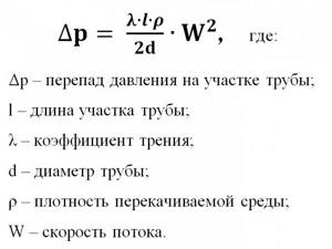
Calculation of losses due to pressure drop in the pipeline is carried out according to the equation:
Why do you need a calculation?
What are the main uses of water in a building? There are several of them:
- Consumption for sanitary and domestic needs.
- Heating device with water coolant.
- Fire extinguishing system water supply.
- Wastewater drainage system.
Each direction has its own characteristics and operating conditions. If the capacity of the pipeline system is insufficient, a critically sharp decrease in pressure is possible, and the possibility of receiving a weak stream from a fire hose will ruin anyone’s mood.
The speed of wastewater flow through the sewerage system is also of particular importance, since the slightest miscalculation in the angle of inclination negatively affects the operation of such a water supply system and its durability. An insufficient angle suggests the possibility of stopping the action, and an excessive one leads to accelerated clogging of the channel.