It should be noted that engineering calculations of water supply and heating systems cannot be called simple, but it is impossible to do without them; only a very experienced practitioner can draw a heating system “by eye” and accurately select pipe diameters. This is if the circuit is quite simple and is designed to heat a small house with a height of 1 or 2 floors. And when we are talking about complex two-pipe systems, they still have to be calculated. This article is for those who decide to independently calculate the heating system of a private home. We will present the methodology somewhat simplified, but in such a way as to obtain the most accurate results.
Plumbing work Tyumen
Using hydraulic calculations, you can select the correct diameters and lengths of pipes, and correctly and quickly balance the system using radiator valves.
The results of this calculation will also help you choose the right circulation pump. As a result of the hydraulic calculation, it is necessary to obtain the following data:
m – coolant flow for the entire heating system, kg/s;
ΔP – pressure loss in the heating system;
ΔP1, ΔP2… ΔPn , – pressure loss from the boiler /pump/ to each radiator /from the first to the n-th/;
where, Q – total power of the heating system, kW – taken from the calculation of heat loss of the building;
Cp – specific heat capacity of water, kJ/(kg*deg.C) – for simplified calculations we take it equal to – 4.19 kJ/(kg*deg.C);
ΔPt – temperature difference at the inlet and outlet – we usually take the boiler flow and return.
How to work in EXCEL
Using Excel tables is very convenient, since the results of hydraulic calculations are always reduced to tabular form. It is enough to determine the sequence of actions and prepare exact formulas.
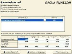
Entering initial data
Select a cell and enter a value. All other information is simply taken into account.
- the D15 value is recalculated in liters, this makes it easier to perceive the flow rate;
- cell D16 - add formatting according to the condition: “If v does not fall within the range of 0.25...1.5 m/s, then the cell background is red/the font is white.”
For pipelines with a difference in inlet and outlet heights, static pressure is added to the results: 1 kg/cm2 per 10 m.
Registration of results
The author's color scheme carries a functional load:
- Light turquoise cells contain the original data - they can be changed.
- Pale green cells are entered constants or data that is little subject to change.
- Yellow cells are auxiliary preliminary calculations.
- Light yellow cells—calculation results.
- Fonts: blue - original data;
- black - intermediate/non-main results;
- red - the main and final results of the hydraulic calculation.
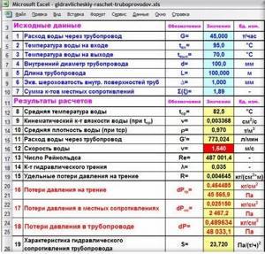
Results in Excel table
Example from Alexander Vorobyov
An example of a simple hydraulic calculation in Excel for a horizontal pipeline section.
- pipe length 100 meters;
- ø108 mm;
- wall thickness 4 mm.

Table of local resistance calculation results
By complicating calculations in Excel step by step, you better master the theory and partially save on design work. Thanks to a competent approach, your heating system will become optimal in terms of costs and heat transfer.
Purpose of hydraulic heating calculation
When any heat supply system operates, hydraulic resistance inevitably arises when the coolant moves. To take this parameter into account, a hydraulic calculation of a two-pipe heating system is required. Its essence lies in the correct selection of system components taking into account their performance characteristics.
In fact, the hydraulic calculation of water heating systems is a complex procedure, during which all the subtleties and nuances are taken into account. At the first stage, you should determine the required heating power, select the optimal piping layout, as well as the thermal operating mode. Based on these data, a hydraulic calculation of the heating system is made in Excel or a specialized program. The result of the calculations should be the following parameters of water heat supply:
- Optimal pipeline diameter . Based on this, you can find out their throughput and heat losses. Taking into account the choice of manufacturing material, the resistance of water on the inner surface of the line will be known;
- Pressure and head losses in certain areas of the system . An example of a hydraulic calculation of a heating system will allow you to think through mechanisms for their compensation in advance;
- Water consumption;
- Required power of pumping equipment . Relevant for closed systems with forced circulation.
At first glance, the hydraulic resistance of a heating system is complex. However, it is enough to delve a little into the essence of the calculations and then you can do them yourself.
To supply heat to a small house or apartment, it is also recommended to calculate the hydraulic resistance of the heating system.
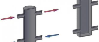
Technical features of gravity heating system
This option for installing a heating system is distinguished by its nuances and has many obvious and undeniable advantages, which usually include the following:
- such a circulation system is capable of independently regulating the work process and distributing the coolant inside the circuit exactly as required by the circuit;
- resistance to any mechanical damage, which is due to the strength of the circuit and the pipes used. The design does not have any quickly wearing parts, due to which a two-pipe gravity heating system, which is traditional, can function properly for more than half a century without the need for any repair work;
- absolute autonomy of work, which is a very important advantage. This system does not depend on whether the electricity is turned on or not, which avoids various unforeseen situations;
- It is not difficult to design such heating with your own hands, since the design of the circuit and its diagram will be extremely clear even to an inexperienced owner. In case of difficulties, you can always study various photo and video materials that can be found from specialists involved in assembling and connecting equipment of this type.
One way or another, the traditional gravity-type heat supply system also has some negative aspects that also cannot be ignored:
- the inertial performance of this equipment will be very large. This means that it will take a very long time from the moment the boiler is ignited to fully heat up;
- Despite the fact that pipe routing is extremely simple, the cost of such equipment is quite high. The thick pipe used for installation has a very considerable price;
- if the system is not connected quite correctly, this will cause a large difference in temperature between the heating radiators;
- due to the fact that the water circulation rate is low, there is a potential risk of freezing of the expansion tank and that part of the circuit that is located in the attic.
Determination of coolant flow and pipe diameters
First, each heating branch must be divided into sections, starting from the very end. The breakdown is done by water consumption, and it varies from radiator to radiator. This means that after each battery a new section begins, this is shown in the example presented above. We start from the 1st section and find the mass flow rate of the coolant in it, focusing on the power of the last heating device:
G = 860q/ ∆t , where:
- G – coolant flow, kg/h;
- q – thermal power of the radiator in the area, kW;
- Δt – temperature difference in the supply and return pipelines, usually 20 ºС.
For the first section, the coolant calculation looks like this:
860 x 2 / 20 = 86 kg/h.
The result obtained must be immediately plotted on the diagram, but for further calculations we will need it in other units - liters per second. To make a translation, you need to use the formula:
GV = G /3600ρ , where:
- GV – volumetric water flow, l/sec;
- ρ – density of water, at a temperature of 60 ºС is equal to 0.983 kg / liter.
We have: 86 / 3600 x 0.983 = 0.024 l/sec. The need to convert units is explained by the need to use special ready-made tables to determine the diameter of a pipe in a private house. They are freely available and are called “Shevelev tables for hydraulic calculations.” You can download them by following the link: https://dwg.ru/dnl/11875
These tables show the diameters of steel and plastic pipes depending on the flow rate and speed of the coolant. If you open page 31, then in Table 1 for steel pipes the first column shows the flow rate in l/sec. In order not to make a full calculation of pipes for the heating system of a private home, you just need to select the diameter according to the flow rate, as shown in the figure below:
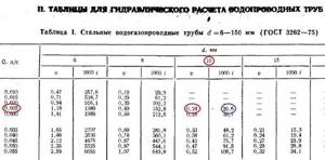
Note. In the left column, under the diameter, the speed of water movement is immediately indicated. For heating systems, its value should be in the range of 0.2–0.5 m/sec.
So, for our example, the internal passage size should be 10 mm. But since such pipes are not used in heating, we can safely accept a DN15 (15 mm) pipeline. We put it on the diagram and move on to the second section. Since the next radiator has the same power, there is no need to apply formulas; we take the previous water flow and multiply it by 2 and get 0.048 l/sec. We turn to the table again and find the closest suitable value in it. At the same time, do not forget to monitor the water flow speed v (m/sec) so that it does not exceed the specified limits (in the figures it is marked in the left column with a red circle):

Important. For heating systems with natural circulation, the coolant movement speed should be 0.1-0.2 m/sec.
As can be seen in the figure, section No. 2 is also laid with a DN15 pipe. Next, using the first formula, we find the flow rate in section No. 3:
Why do the calculations?

Example of a finished heating drawing
The old approach to regulating the heating process differs from the new one in the very mechanism for ensuring hydraulic mode.
Modern heating installations use innovative solutions, materials and designs that are much more economically profitable.
Thanks to this, heating systems contain complex dynamic technologies that subtly respond to changes in temperature.
The benefits are obvious: economical energy consumption, which leads to reduced financial costs.
It is worth considering that installation of such a system requires special knowledge in the specifics of using a high-tech control frame and other elements during installation. Note that the hydraulic calculation and control frame are a guarantee of high-quality operation of current heating systems.
It is advisable to observe the following factors:
- To obtain heat balance with changing air temperatures outside and indoors, it is necessary that there is a sufficient supply of coolant to all elements of the heating system;
- In order to cope with the hydraulic resistance of the heating structure, it is necessary to minimize operating costs, especially with regard to energy costs;
- Minimizing investments during heating installation, which depend most on the diameter of the pipes used;
- Reliability and noiselessness of the entire structure
Two-pipe heating: its advantages and disadvantages
Among the advantages, the following points should be noted:
- two-pipe wiring reduces heat loss to a minimum, since the main line is installed either in the basement or mounted in the floor;
- such a system can be launched in an unfinished house, even when only one floor is ready;
- the fact that the locking system of not only the supply, but also the return riser is located in the basement, allows you to save a lot of space in the house and facilitate repairs and maintenance of the heating structure;
- Residents have the opportunity to independently regulate the heat supply based on their needs - turn on heating in those rooms where it is needed;
- Heating with overhead piping may not be turned off when carrying out repair work on the upper floors.
Disadvantages of two-pipe wiring:
- Arranging such a structure is quite an expensive pleasure. When installing a two-pipe system with your own hands, you will need twice as much materials;
- presence of low pressure in the supply pipe;
- the owner of the property will have to bleed air accumulated in the radiators much more often (about 2 times). An element such as a Mayevsky tap will simplify the removal of air plugs, but it costs a lot of money.
One of the options for the heating system wiring diagram in the video:
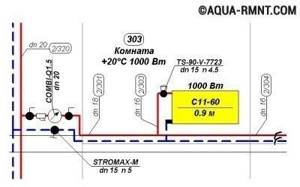
Notation and execution order
The plans must necessarily indicate a predetermined circulation ring, called the main one. It necessarily represents a closed loop, including all sections of the system pipeline with the highest coolant flow. For two-pipe systems, these sections go from the boiler (the source of thermal energy) to the most remote heating device and back to the boiler. For single-pipe systems, a section of the branch is taken - the riser and the return part.
The unit of calculation is a pipeline section having a constant diameter and current (flow rate) of the thermal energy carrier. Its value is determined based on the heat balance of the room. A certain order for designating such segments has been adopted, starting from the boiler (heat source, thermal energy generator), they are numbered. If there are branches from the supply main of the pipeline, they are designated in capital letters in alphabetical order. The same letter with a dash indicates the collection point of each branch on the return main pipeline.
The designation of the beginning of a branch of heating devices indicates the number of the floor (horizontal systems) or the branch - riser (vertical). The same number, but with a dash, is placed at the point of their connection to the return line for collecting coolant flows. In pairs, these designations make up the number of each branch of the calculation section. Numbering is carried out clockwise from the upper left corner of the plan. The length of each branch is determined according to the plan; the error is no more than 0.1 m.
On the floor plan of the heating system, for each segment of it, the thermal load is calculated equal to the heat flow transferred by the coolant; it is taken rounded to 10 W.
After determining for each heating device in the branch, the total heat load on the main supply pipe is determined. As above, here the obtained values are rounded to 10 W. After calculations, each section should have a double designation indicating the value of the heat load , and the length of the section in meters in the denominator.
The required amount (flow) of coolant in each area is easily determined by dividing the amount of heat in the area (corrected by a coefficient taking into account the specific heat capacity of water) by the temperature difference between the heated and cooled coolant in this area. Obviously, the total value for all calculated sections will give the required amount of coolant for the system as a whole.
Without going into details, it should be said that further calculations make it possible to determine the diameters of the pipes of each section of the heating system, the pressure loss on them, and to hydraulically link all circulation rings in complex water heating systems.
Determination of pressure loss in pipes
The pressure loss resistance in the circuit through which the coolant circulates is determined as its total value for all individual components. The latter include:
- losses in the primary circuit, denoted as ∆Plk;
- local coolant costs (∆Plм);
- pressure drop in special zones called “heat generators” under the designation ∆Ptg;
- losses inside the built-in heat exchange system ∆Pto.
After summing these values, the desired indicator is obtained, characterizing the total hydraulic resistance of the system ∆Pco.
In addition to this generalized method, there are other methods for determining pressure loss in polypropylene pipes. One of them is based on a comparison of two indicators tied to the beginning and end of the pipeline. In this case, the pressure loss can be calculated by simply subtracting its initial and final values, determined by two pressure gauges.
Another option for calculating the required indicator is based on the use of a more complex formula that takes into account all the factors that affect the characteristics of the heat flow. The ratio given below primarily takes into account the loss of fluid pressure due to the large length of the pipeline.
- h – liquid pressure loss, in the case under study measured in meters.
- λ – coefficient of hydraulic resistance (or friction), determined using other calculation methods.
- L is the total length of the serviced pipeline, which is measured in linear meters.
- D – internal pipe size, which determines the volume of coolant flow.
- V is the speed of fluid flow, measured in standard units (meter per second).
- The symbol g is the acceleration due to gravity, equal to 9.81 m/s2.

Pressure losses occur due to friction of the fluid against the inner surface of the pipes.
Of great interest are the losses caused by the high coefficient of hydraulic friction. It depends on the roughness of the internal surfaces of the pipes. The ratios used in this case are valid only for pipe blanks of a standard round shape. The final formula for finding them looks like this:
- V is the speed of movement of water masses, measured in meters/second.
- D is the internal diameter, which determines the free space for the coolant to move.
- The coefficient in the denominator indicates the kinematic viscosity of the liquid.
The last indicator refers to constant values and is found using special tables published in large quantities on the Internet.
Specifics of choosing the main branch in a two-pipe system
Based on the practical experience of the calculations carried out, if there is a passing movement of the coolant in a two-pipe scheme, it is better to choose a more loaded riser through the lower battery. In a single-pipe circuit we are talking about a ring through the busiest riser. If hot water has a dead-end movement, in a two-pipe system, select the lower radiator ring of the most loaded remote riser.

The single-pipe scheme assumes an identical approach. In a horizontal circuit, they prefer the ring of the busiest direction of the lower floor. Such work on the hydraulic calculation of a two-pipe heating system should be carried out as carefully as possible, because The slightest mistake can result in major troubles.
· decreased system performance (increased thermal inertia).
To ensure the minimization of capital costs according to the second economic condition - the diameters of pipelines and fittings must be the smallest, but not leading to the appearance of hydraulic noise in the pipelines and shut-off and control valves of the heating system at the calculated coolant flow rate, which occurs at coolant speed values of 0.6–1 .5 m/s depending on the value of the local resistance coefficient.
It is obvious that with the opposite direction of the given requirements for the value of the determined diameter of the pipeline, there is a range of appropriate values for the speed of movement of the coolant. As experience in the construction and operation of heating systems shows, as well as a comparison of capital and operating costs, the optimal range of coolant velocities is within the range of 0.3...0.7 m/s. In this case, the specific pressure loss will be 45...280 Pa/m for polymer pipelines and 60...480 Pa/m for steel water and gas pipes.
Considering the higher cost of pipelines made of polymer materials, it is advisable to adhere to higher coolant flow rates in them to prevent an increase in capital investments during construction. At the same time, operating costs (hydraulic pressure losses) in pipes made of polymer materials in comparison with steel pipes will be lower or remain at the same level due to a significantly lower value of the coefficient of hydraulic friction.
Get full text
To determine the internal diameter of the pipeline din
in the design section of the heating system with a known transported heat flow and temperature difference in the supply and return pipelines
∆tco = 90 – 70 = 20°C (for two-pipe heating systems) or coolant flow, it is convenient to use Table 1. Table
1. Determination of the internal diameter of the system pipelines heating
The further selection of pipelines for life support engineering systems, including heating, consists of determining the type of pipe that, under the planned operating conditions, will ensure maximum reliability and durability. Such high requirements are explained by the fact that pipelines for hot and cold water supply, heating, heat supply for ventilation and air conditioning units, gas supply and other engineering systems pass through almost the entire volume of the building.

The cost of pipelines of all engineering systems in comparison with the cost of the building is less than 0.1%, and an accident or replacement of pipelines when their service life is less than the service life of the building leads to significant additional costs for cosmetic or major repairs, not to mention possible losses in the event of an accident for restoration equipment and material assets located in the building.
All industrial pipes that are used in heating systems can be divided into two large groups - metallic and non-metallic. The main distinguishing feature of metal pipes is mechanical strength, while non-metal pipes are durable.
Based on the predetermined internal diameter of the pipeline, the corresponding nominal diameter dy
for metal pipes or outer diameter and pipe wall thickness
dн xs for polymer (metal-polymer) pipelines.
Different types of pipes have different mechanical, hydraulic and operational characteristics, which have different effects on the processes of hydrodynamics and the distribution of heat flows in the heating system.
It is known that by reducing the hydraulic pressure losses due to friction when the coolant moves in the pipes, the efficiency of regulating the coolant flow (heat flow) of the heating device increases due to the increase (redistribution) of the triggered available pressure on manually or automatically regulated valves, taps, flaps or other fittings. At the same time, they talk about the growth of the authority of the control valve. The authority of the control valves should be understood as the proportion of the pressure located in the regulated area, which is spent on overcoming the local resistance of the valve (valve) during the movement of the coolant.
Hydraulic linkage
Balancing pressure drops in the heating system is carried out using control and shut-off valves.
Hydraulic linking of the system is carried out on the basis of:
- design load (coolant mass flow);
- data from pipe manufacturers on dynamic resistance;
- the number of local resistances in the area under consideration;
- technical characteristics of fittings.
Installation characteristics - pressure drop, fastening, flow capacity - are set for each valve. They are used to determine the coefficients of coolant flow into each riser, and then into each device.
Pressure loss is directly proportional to the square of the coolant flow rate and is measured in kg/h, where
S is the product of dynamic specific pressure, expressed in Pa/(kg/h), and the reduced coefficient for local resistance of the section (ξpr).
The given coefficient ξpr is the sum of all local resistances of the system.
Calculation of hydraulics of a water heating system
The coolant circulates through the system under pressure, which is not a constant value. It is reduced due to the presence of friction forces of water against the walls of pipes, resistance on pipe fittings and fittings. The homeowner also makes his contribution by adjusting the heat distribution in individual rooms.
The pressure increases if the heating temperature of the coolant rises and, vice versa, drops when it decreases.
To avoid imbalance of the heating system, it is necessary to create conditions under which each radiator receives as much coolant as is necessary to maintain the set temperature and replenish the inevitable heat losses.
The main goal of hydraulic calculation is to bring the calculated network costs into line with the actual or operational ones.
At this design stage the following is determined:
- pipe diameter and capacity;
- local pressure losses in individual sections of the heating system;
- hydraulic linkage requirements;
- pressure loss throughout the system (total);
- optimal coolant flow.
To perform a hydraulic calculation, it is necessary to do some preparation:
- Collect initial data and systematize them.
- Select a calculation method.
First of all, the designer studies the thermal parameters of the object and performs a thermal calculation. As a result, he has information about the amount of heat required for each room. After this, heating devices and a heat source are selected.

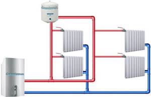
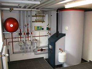
Schematic illustration of a heating system in a private house
At the development stage, a decision is made on the type of heating system and the features of its balancing, pipes and fittings are selected. Upon completion, an axonometric wiring diagram is drawn up, floor plans are developed indicating:
- radiator power;
- coolant flow;
- placement of heating equipment, etc.
Are there free calculation programs?
To simplify the calculation of the heating system of a private house, you can use special programs. Of course, there are not as many of them as graphic editors, but there is still a choice. Some are distributed free of charge, others in demo versions. In any case, it will be possible to make the necessary calculations once or twice without any material investments.
Oventrop CO software
The free software "Oventrop CO" is designed to perform hydraulic calculations for heating a country house.
Oventrop CO was created to provide graphical assistance during the heating design phase. It allows you to perform hydraulic calculations for both one-pipe and two-pipe systems. Working in it is simple and convenient: there are ready-made blocks, error control is provided, and a huge catalog of materials
Based on preliminary settings and selection of heating devices, pipelines and fittings, new systems can be designed. In addition, it is possible to adjust the existing circuit. It is carried out by selecting the power of existing equipment in accordance with the needs of heated rooms and premises.
Both of these options can be combined in this program, allowing you to adjust existing fragments and design new ones. For any calculation option, Oventrop CO selects the valve settings. In terms of performing hydraulic calculations, this program has wide capabilities: from selecting pipeline diameters to analyzing water flow in equipment. All results (tables, diagrams, drawings) can be printed or transferred to the Windows environment.
Software "Instal-Therm HCR"
The "Instal-Therm HCR" program allows you to calculate radiator and surface heating systems.
It comes with the InstalSystem TECE kit, which includes three more programs: Instal-San T (for designing cold and hot water supply), Instal-Heat&Energy (for calculating heat losses) and Instal-Scan (for scanning drawings).
The “Instal-Therm HCR” program is equipped with expanded catalogs of materials (pipes, water consumers, fittings, radiators, thermal insulation and shut-off and control valves). The calculation results are presented in the form of specifications for the materials and products offered by the program. The only drawback of the trial version is that it cannot be printed.
Computing capabilities of "Instal-Therm HCR": - selection by diameter of pipes and fittings, as well as tees, fittings, distributors, bushings and pipeline thermal insulation; — determination of the lifting height of pumps located in the mixers of the system or on the site; — hydraulic and thermal calculations of heating surfaces, automatic determination of the optimal inlet (supply) temperature; — selection of radiators taking into account cooling in the pipelines of the working fluid.
The trial version is free to use, but it has a number of limitations. Firstly, as with most shareware programs, the results cannot be printed, nor can they be exported. Secondly, only three projects can be created in each application of the package. True, you can change them as much as you like. Thirdly, the created project is saved in a modified format. Files with this extension will not be read by any other trial or even standard version.
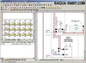
Software "HERZ CO"
The HERZ CO program is freely distributed. With its help, you can make a hydraulic calculation of both one-pipe and two-pipe heating systems. An important difference from others is the ability to perform calculations in new or reconstructed buildings, where a glycol mixture acts as a coolant. This software has a certificate of conformity from CSPS LLC.
"HERZ CO" provides the user with the following options: selection of pipes by diameter, settings of pressure difference regulators (branching, base of drains); analysis of water flow and determination of pressure losses in equipment; calculation of hydraulic resistance of circulation rings; taking into account the necessary authorities of thermostatic valves; reduction of excess pressure in circulation rings by selecting valve settings. For user convenience, graphical data entry is organized. The calculation results are displayed in the form of diagrams and floor plans.
A schematic representation of calculation results in HERZ CO is much more convenient than specifications for materials and products, in the form of which the results of calculations in other programs are displayed
The program has developed contextual help that provides information about individual commands or entered indicators. Multi-window mode allows you to simultaneously view several types of data and results. Working with the plotter and printer is extremely simple; before printing, you can preview the output pages.

The HERZ CO program is equipped with a convenient function for automatically searching and diagnosing errors in tables and diagrams, as well as quick access to catalog data for fittings, heating devices and pipes
Modern control systems with constantly changing thermal conditions require equipment to monitor changes and regulate them.
It is very difficult to make a choice of control valves without knowing the market situation. Therefore, in order to make heating calculations for the area of the entire house, it is better to use a software application with a large library of materials and products. Not only the operation of the system itself, but also the amount of capital investment that will be required for its organization depends on the correctness of the data obtained.