Hydraulic calculation of the heating system: the main goals and objectives of this action

The efficiency of the heating system is not at all guaranteed by high-quality pipes and a high-performance heat generator.
The presence of errors made during installation can negate the operation of a boiler operating at full capacity: either the rooms will be cold, or energy costs will be unreasonably high.
Therefore, it is important to start with the development of a project, one of the most important sections of which is the hydraulic calculation of the heating system
Calculation of hydraulics of a water heating system
The coolant circulates through the system under pressure, which is not a constant value. It is reduced due to the presence of friction forces of water against the walls of pipes, resistance on pipe fittings and fittings. The homeowner also makes his contribution by adjusting the heat distribution in individual rooms.
The pressure increases if the heating temperature of the coolant rises and, vice versa, drops when it decreases.
To avoid imbalance of the heating system, it is necessary to create conditions under which each radiator receives as much coolant as is necessary to maintain the set temperature and replenish the inevitable heat losses.
The main goal of hydraulic calculation is to bring the calculated network costs into line with the actual or operational ones.
At this design stage the following is determined:
- pipe diameter and capacity;
- local pressure losses in individual sections of the heating system;
- hydraulic linkage requirements;
- pressure loss throughout the system (total);
- optimal coolant flow.
To perform a hydraulic calculation, it is necessary to do some preparation:
- Collect initial data and systematize them.
- Select a calculation method.
First of all, the designer studies the thermal parameters of the object and performs a thermal calculation. As a result, he has information about the amount of heat required for each room. After this, heating devices and a heat source are selected.

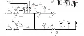
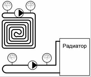
Schematic illustration of a heating system in a private house
At the development stage, a decision is made on the type of heating system and the features of its balancing, pipes and fittings are selected. Upon completion, an axonometric wiring diagram is drawn up, floor plans are developed indicating:
- radiator power;
- coolant flow;
- placement of heating equipment, etc.
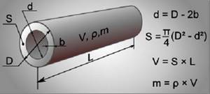
Pipe diameter calculation

Calculation of pipe cross-sections should be based on the results of thermal calculations that are economically justified:
- for a two-pipe system - the difference between tr (hot coolant) and to (cooled - return);
- for single-pipe – coolant flow G, kg/h.
In addition, the calculation must take into account the speed of movement of the working fluid (coolant) - V. Its optimal value is in the range of 0.3-0.7 m/s. The speed is inversely proportional to the internal diameter of the pipe.
When the water speed is 0.6 m/s, characteristic noise appears in the system, but if it is less than 0.2 m/s, there is a risk of air jams.
For calculations, one more speed characteristic will be required - the heat flow rate. It is designated by the letter Q, measured in watts and expressed as the amount of heat transferred per unit time
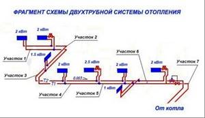
In addition to the above initial data, the calculation will require the parameters of the heating system - the length of each section, indicating the devices connected to it. For convenience, these data can be summarized in a table, an example of which is given below.
Table of plot parameters
How to work in EXCEL
Using Excel tables is very convenient, since the results of hydraulic calculations are always reduced to tabular form. It is enough to determine the sequence of actions and prepare exact formulas.
Entering initial data
Select a cell and enter a value. All other information is simply taken into account.
- the D15 value is recalculated in liters, this makes it easier to perceive the flow rate;
- cell D16 - add formatting according to the condition: “If v does not fall within the range of 0.25...1.5 m/s, then the cell background is red/the font is white.”
For pipelines with a difference in inlet and outlet heights, static pressure is added to the results: 1 kg/cm2 per 10 m.
Registration of results
The author's color scheme carries a functional load:
- Light turquoise cells contain the original data - they can be changed.
- Pale green cells are entered constants or data that is little subject to change.
- Yellow cells are auxiliary preliminary calculations.
- Light yellow cells—calculation results.
- Fonts: blue - original data;
- black - intermediate/non-main results;
- red - the main and final results of the hydraulic calculation.
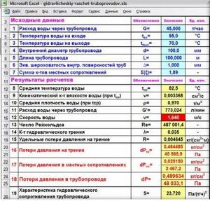
Results in Excel table
Example from Alexander Vorobyov
An example of a simple hydraulic calculation in Excel for a horizontal pipeline section.
- pipe length 100 meters;
- ø108 mm;
- wall thickness 4 mm.

Table of local resistance calculation results
By complicating calculations in Excel step by step, you better master the theory and partially save on design work. Thanks to a competent approach, your heating system will become optimal in terms of costs and heat transfer.
Determination of pipe diameter
To finally determine the diameter and thickness of the heating pipes, it remains to discuss the issue of heat loss.
The maximum amount of heat leaves the room through the walls - up to 40%, through windows - 15%, floor - 10%, everything else through the ceiling/roof. The apartment is characterized by losses mainly through windows and balcony modules
There are several types of heat loss in heated rooms:
- Flow pressure loss in a pipe. This parameter is directly proportional to the product of the specific friction loss inside the pipe (provided by the manufacturer) and the total length of the pipe. But given the current task, such losses can be ignored.
- Pressure losses at local pipe resistances are heat costs at fittings and inside equipment. But given the conditions of the problem, a small number of fitting bends and the number of radiators, such losses can be neglected.
- Heat loss based on the location of the apartment. There is another type of thermal cost, but it is more related to the location of the room relative to the rest of the building. For an ordinary apartment, which is located in the middle of the house and neighbors on the left/right/top/bottom with other apartments, heat losses through the side walls, ceiling and floor are almost equal to “0”.
You can only take into account losses through the front part of the apartment - the balcony and the central window of the common room. But this issue can be resolved by adding 2-3 sections to each of the radiators.
The pipe diameter is selected according to the coolant flow rate and the speed of its circulation in the heating main
Analyzing the above information, it is worth noting that for the calculated speed of hot water in the heating system, the table speed of movement of water particles relative to the pipe wall in a horizontal position is known to be 0.3-0.7 m/s.
To help the master, we present the so-called checklist for performing calculations for a typical hydraulic calculation of a heating system:
- data collection and calculation of boiler power;
- coolant volume and speed;
- heat loss and pipe diameter.
Sometimes, when making calculations, you can get a pipe diameter large enough to cover the calculated volume of coolant. This problem can be solved by increasing the boiler displacement or adding an additional expansion tank.
On our website there is a block of articles devoted to the calculation of the heating system, we recommend that you read:
- Thermal calculation of a heating system: how to correctly calculate the load on the system
- Calculation of water heating: formulas, rules, examples of implementation
- Thermal engineering calculation of a building: specifics and formulas for performing calculations + practical examples
A few important notes
As noted above, there are circulation pumps with a “dry” and “wet” rotor, as well as with an automatic or manual speed control system. Experts recommend using pumps whose rotor is completely immersed in water, not only because of the reduced noise level, but also because such models cope with the load more successfully. The pump is installed in such a way that the rotor shaft is horizontal. Read more about installation here.
In the production of high-quality models, durable steel is used, as well as ceramic shaft and bearings. The service life of such a device is at least 20 years. You should not choose a pump with a cast iron body for a hot water supply system, since under such conditions it will quickly collapse. Preference should be given to stainless steel, brass or bronze.
If noise appears in the system when the pump is operating, this does not always indicate a breakdown. Often the cause of this phenomenon is air remaining in the system after startup. Before starting the system, air should be released through special valves. After the system has operated for several minutes, you need to repeat this procedure and then adjust the pump.
If the start is made using a manually controlled pump, you must first set the device to maximum operating speed; in adjustable models, when starting the heating system, you should simply turn off the lock.
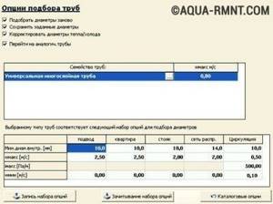
Oventrop co program: choosing polypropylene pipes
Oventrop co is designed for quick calculations. Before work, the necessary settings are made and equipment elements are selected. In this case, various heating schemes are created. Changes are being made to them. This program for hydraulic calculation allows you to determine the coolant flow and select pipes of the required diameter. It helps to perform calculations for one-pipe and two-pipe structures. It's convenient to work with her. The program is equipped with ready-made blocks and material catalogs.
Adjustment of the existing structure is carried out by selecting power and the necessary equipment. The program helps you select the characteristics of the reinforcement.
The calculation results can be transferred to the operating system in a convenient way.
Automation of pumping equipment
To function properly, such pumps must consume electricity. Today, electricity is not cheap, so many people are thinking about how to make the pump more economical in terms of energy consumption.
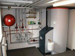
Installing a heating system in a private home is a necessary and extremely important task when you want to create the most comfortable temperature conditions for living in it. The most efficient heating unit is a piping with forced circulation of coolant through the main line. To achieve this task, the system should be retrofitted with a pumping unit
The only problem is that it is necessary to select such equipment in terms of performance, because the efficiency of the entire circuit depends on this. You will learn how to correctly calculate the power of a circulation pump for heating in this article.
To achieve this task, the system should be retrofitted with a pumping unit. The only problem is that it is necessary to select such equipment in terms of performance, because the efficiency of the entire circuit depends on this. You will learn how to correctly calculate the power of a circulation pump for heating in this article.
Two-pipe circuit in a high-rise apartment
To properly install heating in an apartment in a multi-story building, you need to plan everything from the beginning. One of the key points when planning is calculating the diameter of the heating pipe.
The technical part of the matter is called hydraulic calculation. In this case, the choice of the diameter of heating pipes is influenced by the following factors:
- length of the system;
- supply coolant temperature;
- return coolant temperature;
- materials and accessories;
- room area;
- degree of fatigue in the room.
In other words, before calculating the diameter of the heating pipe, you need to determine the hydraulic parameters of the system. You can only make approximate calculations on your own, which can also be used in practice.
The diameter of the pipes for a two-pipe heating system directly determines how quickly the heat from the boiler will reach the end point of the circuit. The smaller the nominal diameter, the higher the coolant velocity.
After all, water will have time to give off more heat over a longer period of time.
The simplest solution for calculating the diameter of a heating pipe is to adhere to the same nominal passage as in the pipe extending into your apartment from the central riser.
This will save you time and nerves, because it is no coincidence that the developer installed a contour with exactly this cross-section. Before the construction of the facility began, all calculations were carried out, including hydraulic ones.
If you want to calculate everything using the formula, then use the information from the next block.
The optimal pipe diameter for heating in an apartment and in a private house up to 100 sq. m is 25 mm. This applies to products made of polypropylene.
Selection of radiators and lengths of pipeline sections
It is necessary to decide on the type of heating devices and indicate their location on the floor plan. Next, a decision must be made on the final configuration of the heating system, the type of pipeline (single-pipe or two-pipe), valves for shut-off and regulation (valves, regulators, valves, pressure, flow and temperature sensors).
Then the drawn diagram indicates the number of thermal loads and the exact length of the sections for which the calculation is made. Finally, a “circulating ring” is defined. It is a closed circuit that includes all consecutive pipeline sections in which an increased flow of coolant is expected at a distance from the source emitting heat energy to the furthest heating device (with a double-circuit system) or to the instrument branch (with a single-pipe system) and back to the heating mechanism.
Notation and execution order
The plans must necessarily indicate a predetermined circulation ring, called the main one. It necessarily represents a closed loop, including all sections of the system pipeline with the highest coolant flow. For two-pipe systems, these sections go from the boiler (the source of thermal energy) to the most remote heating device and back to the boiler. For single-pipe systems, a section of the branch is taken - the riser and the return part.
The unit of calculation is a pipeline section having a constant diameter and current (flow rate) of the thermal energy carrier. Its value is determined based on the heat balance of the room. A certain order for designating such segments has been adopted, starting from the boiler (heat source, thermal energy generator), they are numbered. If there are branches from the supply main of the pipeline, they are designated in capital letters in alphabetical order. The same letter with a dash indicates the collection point of each branch on the return main pipeline.
The designation of the beginning of a branch of heating devices indicates the number of the floor (horizontal systems) or the branch - riser (vertical). The same number, but with a dash, is placed at the point of their connection to the return line for collecting coolant flows. In pairs, these designations make up the number of each branch of the calculation section. Numbering is carried out clockwise from the upper left corner of the plan. The length of each branch is determined according to the plan; the error is no more than 0.1 m.
On the floor plan of the heating system, for each segment of it, the thermal load is calculated equal to the heat flow transferred by the coolant; it is taken rounded to 10 W.
After determining for each heating device in the branch, the total heat load on the main supply pipe is determined. As above, here the obtained values are rounded to 10 W. After calculations, each section should have a double designation indicating the value of the heat load , and the length of the section in meters in the denominator.
The required amount (flow) of coolant in each area is easily determined by dividing the amount of heat in the area (corrected by a coefficient taking into account the specific heat capacity of water) by the temperature difference between the heated and cooled coolant in this area. Obviously, the total value for all calculated sections will give the required amount of coolant for the system as a whole.
Without going into details, it should be said that further calculations make it possible to determine the diameters of the pipes of each section of the heating system, the pressure loss on them, and to hydraulically link all circulation rings in complex water heating systems.
Are there free calculation programs?
To simplify the calculation of the heating system of a private house, you can use special programs. Of course, there are not as many of them as graphic editors, but there is still a choice. Some are distributed free of charge, others in demo versions. In any case, it will be possible to make the necessary calculations once or twice without any material investments.
Oventrop CO software
The free software "Oventrop CO" is designed to perform hydraulic calculations for heating a country house.
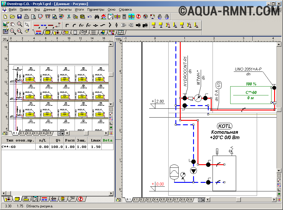
Oventrop CO was created to provide graphical assistance during the heating design phase. It allows you to perform hydraulic calculations for both one-pipe and two-pipe systems. Working in it is simple and convenient: there are ready-made blocks, error control is provided, and a huge catalog of materials
Based on preliminary settings and selection of heating devices, pipelines and fittings, new systems can be designed. In addition, it is possible to adjust the existing circuit. It is carried out by selecting the power of existing equipment in accordance with the needs of heated rooms and premises.
Both of these options can be combined in this program, allowing you to adjust existing fragments and design new ones. For any calculation option, Oventrop CO selects the valve settings. In terms of performing hydraulic calculations, this program has wide capabilities: from selecting pipeline diameters to analyzing water flow in equipment. All results (tables, diagrams, drawings) can be printed or transferred to the Windows environment.
Software "Instal-Therm HCR"
The "Instal-Therm HCR" program allows you to calculate radiator and surface heating systems.
It comes with the InstalSystem TECE kit, which includes three more programs: Instal-San T (for designing cold and hot water supply), Instal-Heat&Energy (for calculating heat losses) and Instal-Scan (for scanning drawings).
The “Instal-Therm HCR” program is equipped with expanded catalogs of materials (pipes, water consumers, fittings, radiators, thermal insulation and shut-off and control valves). The calculation results are presented in the form of specifications for the materials and products offered by the program. The only drawback of the trial version is that it cannot be printed.
Computing capabilities of "Instal-Therm HCR": - selection by diameter of pipes and fittings, as well as tees, fittings, distributors, bushings and pipeline thermal insulation; — determination of the lifting height of pumps located in the mixers of the system or on the site; — hydraulic and thermal calculations of heating surfaces, automatic determination of the optimal inlet (supply) temperature; — selection of radiators taking into account cooling in the pipelines of the working fluid.
The trial version is free to use, but it has a number of limitations. Firstly, as with most shareware programs, the results cannot be printed, nor can they be exported. Secondly, only three projects can be created in each application of the package. True, you can change them as much as you like. Thirdly, the created project is saved in a modified format. Files with this extension will not be read by any other trial or even standard version.
Overview of hydraulic calculation programs
Example program for heating calculations
In fact, any hydraulic calculation of water heating systems is a complex engineering task. To solve this problem, a number of software packages have been developed that simplify this procedure.
You can try to make a hydraulic calculation of the heating system in Excel using ready-made formulas. However, the following problems may arise:
- Large error. In most cases, one-pipe or two-pipe schemes are taken as an example of the hydraulic calculation of a heating system. Finding similar calculations for a collector is problematic;
- To correctly account for the hydraulic resistance of the pipeline, reference data is required, which is not included in the form. They need to be searched for and entered additionally.
Considering these factors, experts recommend using calculation programs. Most of them are paid, but some have a demo version with limited features.
Oventrop CO
Hydraulic calculation program
The simplest and most understandable program for hydraulic calculations of a heating system. An intuitive interface and flexible settings will help you quickly understand the nuances of data entry. Minor problems may arise during the initial setup of the complex. It will be necessary to enter all the system parameters, from the pipe material to the location of the heating elements.
It is characterized by flexibility of settings, the ability to make simplified hydraulic heating calculations both for a new heating system and for modernizing an old one. It differs from analogues in its convenient graphical interface.
Instal-Therm HCR
The software package is designed for professional hydraulic resistance of a heating system. The free version has many limitations. Area of application: heating design in large public and industrial buildings.
In practice, for autonomous heat supply of private houses and apartments, hydraulic calculations are not always performed. However, this can lead to deterioration of the heating system and rapid failure of its elements - radiators, pipes and boiler. To avoid this, you need to timely calculate the system parameters and compare them with the actual ones to further optimize the heating operation.
Example of hydraulic calculation of a heating system:
Hydraulic calculation methods
As we have already said, hydraulic calculations can be done using an online calculator, using a special program, or in an Excel spreadsheet. The first option is suitable even for those who do not understand anything about heating engineering and hydraulics. Naturally, this method can only obtain approximate values, which cannot be used in large and complex projects.

An example of an axonometric diagram.
The software is very expensive and there is no point in buying it at once, but you can make a table in Excel without investment. You can perform the calculation using different formulas:
- theoretical hydraulics;
- SNIP 2.04.02-84.
But the calculation method may also differ: specific pressure loss or resistance characteristics. The latter cannot be used for gravity systems with natural coolant circulation. When installing small two-pipe heating circuits with forced circulation, it is enough to follow a few simple rules. The main lines are made of polypropylene pipes with an outer diameter of 25 mm. Branches to radiators are made of 20 mm pipes. We wrote about how to choose a pump.
Calculation of heat loss at home
This data will be needed to determine the required power of the heating system, i.e. the boiler, and the thermal power of each radiator separately. To do this, you can use our online heat loss calculator. They need to be calculated for each room in the house that has an external wall.
Examination. We divide the calculated heat loss of each room by its quadrature and obtain the specific heat loss in W/sq.m. They usually range from 50 to 150 W/sq. m. If your indicators differ greatly from those given, then a mistake may have been made. The heat losses of the rooms on the top floor are the greatest, followed by the heat losses of the first floor and the least in the rooms of the middle floors.
Example initial conditions
For a more specific explanation of all the details of the hydraulic calculation, let’s take a specific example of an ordinary living space. We have a classic 2-room apartment in a panel house with a total area of 65.54 m2, which includes two rooms, a kitchen, separate toilet and bathroom, a double corridor, a twin balcony.
After commissioning, we received the following information regarding the readiness of the apartment. The described apartment includes walls made of monolithic reinforced concrete structures treated with putty and primer, profile windows with two-chamber glass, pressed interior doors, ceramic tiles on the bathroom floor.

A typical 9-storey panel house with four entrances. There are 3 apartments on each floor: one 2-room and two 3-room. The apartment is located on the fifth floor
In addition, the presented housing is already equipped with copper wiring, distributors and a separate panel, a gas stove, a bathtub, a washbasin, a toilet, a heated towel rail, and a sink.
And most importantly, the living rooms, bathroom and kitchen already have aluminum heating radiators. The question regarding the pipes and boiler remains open.
What does hydraulic calculation give us?
- Loss of heat and pressure carrier in the system itself.
- The required diameter of pipes in the most critical sections of the pipeline. In this case, it is necessary to take into account what the required and materially feasible speeds of coolant movement are.
- Hydrocoupling of all branches of the heating system. At the same time, in order to balance the system in different operating modes, it is necessary to use the previously mentioned adjustment fittings.
- Loss of pressure on other sections of the pipeline.
Important information! During the design and installation of a heating system, the most labor-intensive and critical stage of work is considered to be the hydraulic calculation.
But before making a hydraulic calculation of the heating system, you must first perform a number of procedures.
Photos in the text to illustrate what was said
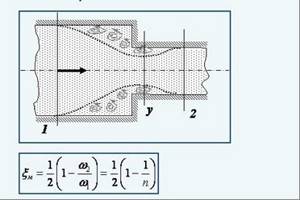
Loss of fluid pressure due to sudden constriction
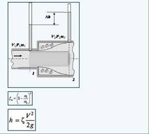
Pressure loss due to sudden expansion of pipes
Calculation of hydraulic resistance in a heating network
Scheme of hydraulic calculation of a network section
Calculation formulas for heating pipes

Selection of expansion tank
Thus, we can summarize that the hydraulic calculation of heating networks is a very important and critical stage in the design of heat supply systems for any facility, from a small country house to a residential area with tens of thousands of square meters. First of all, such a calculation helps to correctly select all the necessary equipment and shut-off and control valves to ensure optimal performance of the heating network.
Conclusions and useful video on the topic
Features, advantages and disadvantages of natural and forced coolant circulation systems for heating systems:
Summarizing the hydraulic calculations, the result was specific physical characteristics of the future heating system.
Naturally, this is a simplified calculation scheme that provides approximate data regarding hydraulic calculations for the heating system of a typical two-room apartment.
Are you trying to do a hydraulic calculation of your heating system yourself? Or maybe you don’t agree with the material presented? We are waiting for your comments and questions - the feedback block is located below.