Pipe diameter, flow speed and coolant flow.
This material is designed to understand what diameter, flow rate and flow velocity are. And what are the connections between them. Other materials will contain detailed calculations of the diameter for heating.
In order to calculate the diameter you need to know:
| 1. Coolant (water) flow in the pipe. 2. Resistance to the movement of coolant (water) in a pipe of a certain length. |
Here are the necessary formulas you need to know:
| S-Sectional area m 2 of the internal lumen of the pipe π-3.14-constant - the ratio of the circumference to its diameter. r-Radius of a circle equal to half the diameter, m Q-water flow m 3 /s D-Inner diameter of the pipe, m V-coolant flow rate, m/s |
Resistance to coolant movement.
Any coolant moving inside the pipe tends to stop its movement. The force that is applied to stop the movement of the coolant is the resistance force.
This resistance is called pressure loss. That is, a moving coolant through a pipe of a certain length loses pressure.
Head is measured in meters or pressure (Pa). For convenience, it is necessary to use meters in calculations.
In order to better understand the meaning of this material, I recommend following the solution to the problem.
Water flows in a pipe with an internal diameter of 12 mm at a speed of 1 m/s. Find the flow rate.
Solution:
You must use the above formulas:
| 1. Find the cross section 2. Find the flow rate |
| D=12mm=0.012 m p=3.14 |
S=3.14•0.012 2 /4=0.000113 m 2
Q=0.000113•1=0.000113 m 3 /s = 0.4 m 3 /h.
There is a pump that creates a constant flow of 40 liters per minute. A 1 meter long pipe is connected to the pump. Find the internal diameter of the pipe at a water speed of 6 m/s.
Q=40l/min=0.000666666 m 3 /s
From the above formulas I got the following formula.
Each pump has the following flow-resistance characteristic:
This means that our flow rate at the end of the pipe will depend on the pressure loss that is created by the pipe itself.
| The longer the pipe, the greater the pressure loss. The smaller the diameter, the greater the pressure loss. The higher the coolant velocity in the pipe, the greater the pressure loss. Corners, turns, tees, narrowing and expansion of the pipe also increase pressure loss. |
The pressure loss along the length of the pipeline is discussed in more detail in this article:
Now let's look at a problem from a real example.
The steel (iron) pipe is laid 376 meters long with an internal diameter of 100 mm; there are 21 bends along the length of the pipe (angular turns 90°C). The pipe is laid with a difference of 17 m. That is, the pipe goes up relative to the horizon to a height of 17 meters. Pump characteristics: Maximum head 50 meters (0.5 MPa), maximum flow 90 m 3 / h. Water temperature 16°C. Find the maximum possible flow rate at the end of the pipe.
| D = 100 mm = 0.1 m L = 376 m Geometric height = 17 m Branches 21 pcs Pump pressure = 0.5 MPa (50 meters of water column) Maximum flow = 90 m 3 / h Water temperature 16 ° C. Steel iron pipe |
Find the maximum flow rate =?
Video solution:
To solve, you need to know the pump schedule: Dependence of flow on pressure.
In our case, the graph will look like this:
Look, I marked 17 meters with a broken line along the horizon and at the intersection along the curve I get the maximum possible flow rate: Qmax.
According to the graph, I can safely say that due to the difference in height, we lose approximately: 14 m 3 / hour. (90-Qmax=14 m 3 /h).
The stepwise calculation is obtained because in the formula there is a quadratic feature of pressure loss in dynamics (motion).
Therefore, we solve the problem step by step.
Since we have a flow range from 0 to 76 m 3 /hour, I would like to check the pressure loss at a flow rate equal to: 45 m 3 /hour.
Finding the speed of water movement
Q=45 m 3 /h = 0.0125 m 3 /sec.
V = (4•0.0125)/(3.14•0.1•0.1)=1.59 m/s
Finding the Reynolds number
ν=1.16•10 -6 =0.00000116. Taken from the table. For water at a temperature of 16°C.
Δe=0.1mm=0.0001m. Taken from the table for a steel (iron) pipe.
Next, we check the table, where we find the formula for finding the coefficient of hydraulic friction.
I get it in the second area, provided
10•D/Δe 0.25 =0.11•(0.0001/0.1 + 68/137069) 0.25 =0.0216
Next we finish with the formula:
h=λ•(L•V 2 )/(D•2•g)= 0.0216•(376•1.59•1.59)/(0.1•2•9.81)=10.46 m.
As you can see, the loss is 10 meters. Next, we determine Q1, see the graph:
Now we make the original calculation at a flow rate of 64 m 3 / hour
Q=64 m 3 /h = 0.018 m 3 /sec.
V = (4•0.018)/(3.14•0.1•0.1)=2.29 m/s
λ=0.11(Δe/D + 68/Re) 0.25 =0.11•(0.0001/0.1 + 68/197414) 0.25 =0.021
h=λ•(L•V 2 )/(D•2•g)= 0.021•(376•2.29 •2.29)/(0.1•2•9.81)=21.1 m.
We mark on the graph:
Qmax is at the intersection of the curve between Q1 and Q2 (Exactly the middle of the curve).
Answer: The maximum flow rate is 54 m 3 /h. But we solved this without resistance when cornering.
Temperature graph of the heating system - calculation procedure and ready-made tables
The basis for an economical approach to energy consumption in a heating system of any type is the temperature schedule. Its parameters indicate the optimal value for heating water, thereby optimizing costs. In order to apply this data in practice, it is necessary to learn in more detail the principles of its construction.
Terminology
Temperature graph - the optimal heating value of the coolant to create a comfortable temperature in the room. It consists of several parameters, each of which directly affects the quality of operation of the entire heating system.
- Temperature in the inlet and outlet pipes of the heating boiler.
- The difference between these coolant heating indicators.
- Temperature indoors and outdoors.
The latter characteristics are decisive for the regulation of the first two. Theoretically, the need to increase the heating of water in the pipes occurs when the temperature outside decreases. But how much do you need to increase the boiler power in order to heat the air in the room optimally? To do this, draw up a graph of the dependence of the parameters of the heating system.
- 150°C/70°C. Before reaching the users, the coolant is diluted with water from the return pipe to normalize the incoming temperature.
- 90°C/70°C. In this case, there is no need to install equipment for mixing the flows.
According to the current system parameters, utilities must monitor compliance with the heating value of the coolant in the return pipe. If this parameter is less than normal, it means that the room is not heated properly. Exceeding indicates the opposite - the temperature in the apartments is too high.

Temperature chart for a private house
The practice of drawing up such a schedule for autonomous heating is not very developed. This is explained by its fundamental difference from the centralized one. The water temperature in the pipes can be controlled manually or automatically. If the design and practical implementation took into account the installation of sensors for automatically regulating the operation of the boiler and thermostats in each room, then there will be no urgent need to calculate the temperature schedule.
But it will be indispensable for calculating future expenses depending on weather conditions. In order to draw it up in accordance with the current rules, the following conditions must be taken into account:
- Heat losses at home should be within normal limits. The main indicator of this condition is the heat transfer resistance coefficient of the walls. It varies depending on the region, but for central Russia you can take the average value - 3.33 m²*C/W.
- Uniform heating of living spaces in the house when the heating system is operating. This does not take into account the forced decrease in temperature in one or another element of the system. Ideally, the amount of thermal energy from the heating device (radiator), as far as possible from the boiler, should be equal to that installed close to it.
Only after these conditions have been met can we proceed to the calculation part. Difficulties may arise at this stage. Correct calculation of an individual temperature schedule is a complex mathematical scheme that takes into account all possible indicators.
However, to make the task easier, there are ready-made tables with indicators. Below are examples of the most common operating modes of heating equipment. The following input data were taken as initial conditions:
- Minimum air temperature outside - 30°C
- The optimal room temperature is +22°C.
Based on these data, schedules were drawn up for the following types of operation of heating systems.
It is worth remembering that these data do not take into account the design features of the heating system. They only show the recommended temperature and power values of heating equipment depending on weather conditions.
eco-sip.ru
- putty
- Building a wall
- Painting
- Wallpaper
- Decorating the walls
- Facade panels
- Other materials
The speed of water movement in the pipes of the heating system.
During the lectures we were told that the optimal speed of water movement in the pipeline is 0.8-1.5 m/s. On some sites I see something similar (specifically about the maximum of one and a half meters per second).
BUT the manual says to take losses per linear meter and speed - according to the appendix in the manual. The speeds there are completely different, the maximum that is on the sign is just 0.8 m/s.
And in the textbook I came across an example of a calculation where the speeds do not exceed 0.3-0.4 m/s.
So what's the point? How to take it in general (and how in reality, in practice)?
I am attaching a screenshot of the sign from the manual.
Thank you all in advance for your answers!
What do you want? Should you find out “military secrets” (how to actually do it), or pass the coursework? If only a course student - then according to the manual, which the teacher wrote and does not know anything else and does not want to know. And if you do it right
, won’t accept it yet.
0.036*G^0.53 - for heating risers
0.034*G^0.49 - for mm mains of the branch, until the load is reduced to 1/3
0.022*G^0.49 - for the end sections of a branch with a load of 1/3 of the entire branch
In the coursework, I calculated it according to the manual. But I wanted to know how things were going.
That is, it turns out in the textbook (Staroverov, M. Stroyizdat) is also not correct (speeds from 0.08 to 0.3-0.4). But perhaps there is only an example of calculation.
Offtop: That is, you also confirm that, in essence, the old (relatively) SNiPs are in no way inferior to the new ones, and in some cases even better. (many teachers tell us about this. In general, the dean of the PSP says that their new SNiP largely contradicts both the laws and himself).
But in principle everything was explained.
and the calculation to reduce diameters along the flow seems to save materials. but increases labor costs for installation. If the labor is cheap, it might make sense. if labor is expensive, there is no point. And if over a long length (heating main) changing the diameter is beneficial, fussing with these diameters within the house does not make sense.
and there is also the concept of hydraulic stability of the heating system - and here the ShaggyDoc schemes win
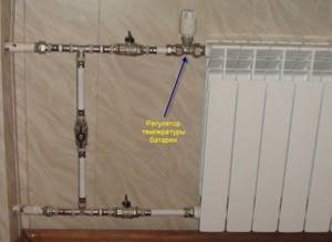
We disconnect each riser (upper wiring) from the main line with a valve. I've seen that double adjustment taps are installed immediately after the valve. Is it advisable?
And how to disconnect the radiators themselves from the connections: with valves, or install a double adjustment tap, or both? (that is, if this valve could completely shut off the pipeline, then the valve would not be needed at all?)
And for what purpose are pipeline sections isolated? (designation - spiral)
The heating system is two-pipe.
I need to know specifically about the supply pipeline, the question is above.
We have a coefficient of local resistance to the flow input with a turn. Specifically, we use it at the entrance through the louvered grille to the vertical channel. And this coefficient is 2.5 - which is quite a lot.
That is, how to come up with something to get rid of this. One of the exits is if the grille is “in the ceiling”, and then there will be no turning entrance (although there will still be a small one, since the air will be drawn along the ceiling, moving horizontally, and move towards this grille, turn in a vertical direction, but along logically it should be less than 2.5).
You can't put bars in the ceiling in an apartment building, neighbors. and in a single-apartment building, the ceiling will not be beautiful with bars, and debris can get in. that is, the problem cannot be solved this way.
I often drill, then plug
Take the thermal power and the initial from the final temperature. Based on these data, you can absolutely reliably calculate
speed. It will most likely be a maximum of 0.2 m\S. Higher speeds require a pump.
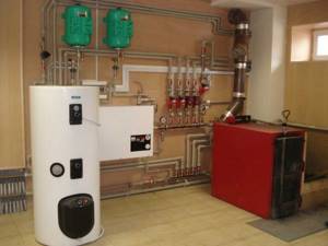
Heating systems with pump circulation
As has already been mentioned several times, the main disadvantage of a heating system with natural circulation of coolant is the low circulation pressure (especially in an apartment system) and, as a result, the increased diameter of the pipes. It is enough to make a slight mistake with the choice of pipe diameters and the coolant is already “squeezed” and cannot overcome the hydraulic resistance. You can “unclamp” the system without any significant alterations: turn on the circulation pump (Fig. 12) and move the expansion tank from the supply to the return. It should be noted that moving the expander to the return line is not always necessary. When simply altering a simple heating system, for example, an apartment heating system, the tank can be left where it was. With proper reconstruction or installation of a new system, the tank is moved to the return line and replaced from open to closed.
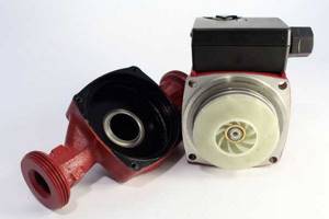
rice. 12. Circulation pump
What power should the circulation pump have, how and where should it be installed?
Circulation pumps for household heating systems have low electricity consumption - about 60-100 watts, that is, like a regular light bulb, they do not lift water, but only help it overcome local resistance in the pipes. These pumps can be compared to the propeller of a ship: the propeller pushes water and ensures the movement of the ship, but at the same time the water in the ocean does not decrease or increase, that is, the overall balance of water remains the same. The circulation pump attached to the pipeline pushes water, but no matter how much it pushes it out, the same amount of water comes to it from the other side, that is, fears that the pump will push the coolant through the open expander are in vain: the heating system is a closed circuit and the quantity there is constant water in it. In addition to circulation pumps, centralized systems can include booster pumps that increase pressure and are capable of lifting water; they should actually be called pumps, but circulation pumps, translated into a generally understandable language, can hardly be called pumps - so... fans. No matter how much an ordinary household fan drives air around the apartment, all it can do is create a breeze (air circulation), but it is not able to change the atmospheric pressure even in a tightly closed room.
As a result of the use of a circulation pump, the radius of action of the heating system is significantly increased, the diameters of pipelines are reduced and the possibility of connecting systems to boilers with increased coolant parameters is created. To ensure silent operation of a water heating system with pump circulation, the speed of movement of the coolant should not exceed: in pipelines laid in the main premises of residential buildings, with nominal pipe diameters of 10, 15 and 20 mm or more, respectively, 1.5; 1.2 and 1 m/s; in pipelines laid in auxiliary premises of residential buildings - 1.5 m/s; in pipelines laid in auxiliary buildings - 2 m/s.
To ensure the noiselessness of the system and its delivery of the required volume of coolant, it is necessary to make a small calculation. We already know how to roughly determine the required boiler power (in kilowatts), based on the area of the heated premises. The optimal water flow rate passing through the boiler, recommended by many boiler equipment manufacturers, is calculated using a simple empirical formula: Q=P, where Q is the coolant flow rate through the boiler, l/min; P - boiler power, kW. For example, for a 30 kW boiler, the water flow is approximately 30 l/min. To determine the coolant flow rate in any section of the circulation ring, we use the same formula, knowing the power of the radiators installed in this section, for example, we calculate the water flow rate for radiators installed in one room. Let's assume that the power of the radiators is 6 kW, which means that the coolant flow rate will be approximately 6 l/min.
Based on water flow, we determine the diameters of the pipelines (Table 1). These values correspond to the practically accepted correspondence between pipe diameters and the flow rate of coolant flowing through them at a speed of no more than 1.5 meters per second.
Table 1
Correspondence of pipeline diameters with coolant flow
| Consumption, l/min | 5,7 | 15 | 30 | 53 | 83 | 170 | 320 |
| Diameter, inches | 1/2 | 3/4 | 1 | 1¼ | 1½ | 2 | 2½ |
Next, we determine the power of the circulation pump. For every 10 meters of circulation ring length, 0.6 meters of pump pressure is required. For example, if the total length of the pipeline ring is 90 meters, the pump head should be 5.4 meters. We go to the store (or select it from a catalog) and purchase a pump with a pressure that suits us. If pipes of smaller diameters than those recommended in the previous paragraph are used, the pump power should be increased, since the thinner the pipes, the greater their hydraulic resistance. And accordingly, when using pipes of large diameters, the pump power can be reduced.
In order to ensure constant circulation of water in heating systems, it is advisable to install at least two circulation pumps, one of which is working, the other (on the bypass) is backup. Or one pump is installed on the system, and the other is kept in a secluded place, in case of a quick replacement if the first one breaks down.
It should be noted that the calculation of the heating system given here is extremely primitive and does not take into account many factors and features of the individual heating system. If you are building a cottage with a complex heating system architecture, then it is necessary to make accurate calculations. This can only be done by heating engineers. It is extremely unreasonable to build a multi-million dollar structure without as-built documentation - a project that takes into account all the features of the construction.
The circulation pump in the heating system is filled with water and experiences equal (if the water is not heated) hydrostatic pressure on both sides - from the inlet (suction) and outlet (discharge) pipes connected to the heat pipes. Modern circulation pumps, made with water-lubricated bearings, can be placed on both the supply and return pipelines, but most often they are installed on the return. Initially, this was due to a purely technical reason: when placed in colder water, the service life of the bearings, rotor and stuffing box through which the pump shaft passes increased. And now they are put on the return line rather out of habit, since from the point of view of creating artificial circulation of water in a closed circuit, the location of the circulation pump is indifferent. Although placing them on the supply pipeline, where hydrostatic pressure is usually lower, is more rational. For example, an expansion tank is installed in your system at a height of 10 m from the boiler, which means it creates a static pressure of 10 m of water column, but this statement is true only for the lower pipeline; in the upper one the pressure will be less, since the water column here will be smaller. Wherever we place the pump, it will be subject to the same pressure on both sides, even if it is placed on a vertical main supply or return riser, the pressure difference between the two pipes of the pump will be small, since the pumps are small in size.
However, everything is not so simple. A pump operating in a closed circuit of the heating system increases circulation by pumping water into the heat pipe on one side and sucking it in on the other. The water level in the expansion tank will not change when the circulation pump is started, since a uniformly operating pump only ensures circulation with a constant amount of water. Since under these conditions (uniformity of pump action and constant volume of water in the system) the water level in the expansion tank remains unchanged, it does not matter whether the pump is running or not, the hydrostatic pressure at the point where the expander connects to the system pipes will be constant. This point is called neutral, since the circulation pressure developed by the pump does not in any way affect the static pressure created by the expansion tank. In other words, the pressure of the circulation pump at this point is zero.
In any closed hydraulic system, the circulation pump uses the expansion tank as a reference point at which the pressure developed by the pump changes its sign: up to this point the pump, creating compression, pumps water, after it, causing a vacuum, it sucks in water. All heat pipes of the system from the pump to the point of constant pressure (counting in the direction of water movement) will belong to the pump discharge zone. All heat pipes after this point go to the suction zone. In other words, if the circulation pump is inserted into the pipeline immediately after the expansion tank connection point, it will suck water from the tank and pump it into the system; if the pump is installed before the tank connection point, the pump will pump water out of the system and pump it into the tank.
So what, what difference does it make to us whether the pump pumps water out of the tank or pumps it into it, as long as it rotates it through the system. But there is a significant difference: the static pressure created by the expansion tank interferes with the operation of the system. In pipelines located in the pump discharge area, an increase in hydrostatic pressure compared to the water pressure at rest must be taken into account. On the contrary, in pipelines located in the suction zone of the pump, it is necessary to take into account the decrease in pressure, and it is possible that the hydrostatic pressure will not only drop to atmospheric pressure, but even a vacuum may occur. That is, as a result of the pressure difference in the system, there is a danger of suction or release of air or boiling of the coolant.
In order to avoid disruption of water circulation due to its boiling or air suction, when designing and hydraulically calculating water heating systems, the following rule must be observed: in the suction zone at any point in the heating system pipelines, hydrostatic pressure must remain excessive when the pump operates. There are four possible ways to implement this rule (Fig. 13).
rice. 13. Schematic diagrams of heating systems with pump circulation and an open expansion tank
1. Raising the expansion tank to a sufficient height (usually at least 80 cm). This is a fairly simple method for reconstructing systems with natural circulation into a pump circulation, but it requires a significant attic space and careful insulation of the expansion tank. 2. Moving the expansion tank to the most dangerous upper point in order to include the upper line in the discharge zone. A clarification is necessary here. In new heating systems, supply pipelines with pump circulation are made with slopes not from the boiler, but towards the boiler, so that air bubbles move along with the water, since the driving force of the circulation pump will not allow them to float “against the flow”, as was the case in systems with natural circulation. Therefore, the highest point of the system is not at the main riser, but at the most distant one. For the reconstruction of an old system with natural circulation to the pumping station, this method is quite labor-intensive, since it requires alteration of the pipelines, and for creating a new system, it is not justified, since other, more successful options are possible. 3. Connect the expansion tank pipe near the suction pipe of the circulation pump. In other words, if we reconstruct an old system with natural circulation, then we simply cut off the tank from the supply line and connect it to the return line behind the circulation pump and thereby create the most favorable conditions for the pump. 4. We depart from the usual scheme of placing the pump on the return line and plug it into the supply line immediately after the expansion tank connection point. When reconstructing a system with natural circulation, this is the simplest method: we simply cut the pump into the supply pipe without altering anything else. However, you need to be very careful when choosing a pump; after all, we place it in unfavorable conditions of high temperatures. The pump will have to serve for a long time and reliably, and only reputable manufacturers can guarantee this.
The modern market for plumbing and heating fittings makes it possible to replace open expansion tanks with closed ones. In a closed tank, there is no contact of the system fluid with air: the coolant does not evaporate and is not enriched with oxygen. This reduces heat and water losses and reduces internal corrosion of heating devices. Liquid will never spill out of a closed tank.
A closed-type expansion tank (“expanzomat”) is a spherical or oval-shaped capsule, divided inside by a sealed membrane into two parts: air and liquid. A nitrogen-containing mixture is pumped into the air part of the housing under a certain pressure. Before the heating system is filled with water, the pressure of the gas mixture inside the tank tightly presses the diaphragm to the water part of the tank. Heating the water leads to the creation of working pressure and an increase in the volume of coolant - the membrane bends towards the gas part of the tank. At maximum operating pressure and maximum increase in water volume, the water part of the tank is filled and the gas mixture is compressed to its maximum. If the pressure continues to rise and the volume of coolant continues to increase, then the safety valve is activated, releasing water (Fig. 14).
rice. 14. Membrane type expansion tank
The volume of the tank is selected such that its useful volume is not less than the volume of thermal expansion of the coolant, and the preliminary air pressure in the gas part of the tank is made equal to the static pressure of the coolant column in the system. This selection of gas mixture pressure allows you to keep the membrane in an equilibrium (not tense) position when the heating system is filled but not turned on.
A closed tank can be placed at any point in the system, but, as a rule, it is installed next to the boiler, since the temperature of the liquid at the location where the expansion tank is installed should be as low as possible. And we already know that it is best to install the circulation pump immediately behind the expander, where the most favorable conditions are created for it (and for the heating system as a whole) (Fig. 15).
rice. 15. Schematic diagrams of heating systems with pump circulation and a closed expansion tank
However, with such a heating system design, we are faced with two problems: air removal and increased pressure on the boiler.
If in systems with open expansion tanks the air was removed through the expander countercurrently (in systems with natural circulation) or along the way (in systems with pump circulation), then this does not happen with closed tanks. The system is completely closed and there is simply nowhere for air to escape. To remove air pockets, automatic air bleeders are installed at the top of the pipeline - devices equipped with floats and shut-off valves. As the pressure increases, the valve is activated and releases air into the atmosphere. Or Mayevsky taps are installed on each heating radiator. This part, installed on heating devices, allows you to bleed the air plug directly from the radiators. The Mayevsky tap is included with some radiator models, but is often offered separately.
rice. 16. Automatic air vent
The principle of operation of air vents (Fig. 16) is that in the absence of air, a float inside the device keeps the exhaust valve closed. As air collects in the float chamber, the water level inside the air vent drops. The float lowers and the outlet valve opens, through which air is released into the atmosphere. After the air is released, the water level in the air vent rises and the float floats, which leads to the closure of the exhaust valve. The process continues until air re-collects in the float chamber and lowers the water level, lowering the float. Automatic air vents are manufactured in different designs, shapes and sizes and can be installed both on the main pipeline and directly (L-shaped) on radiators.
The Mayevsky valve, in contrast to an automatic air vent, is, in general, an ordinary plug with an air vent channel and a conical screw screwed into it: by turning the screw, the channel is released and the air comes out. Turning the screw closes the channel. There are also air vents in which, instead of a conical screw, a metal ball is used to block the air discharge channel.
Instead of automatic air vents and Mayevsky taps, an air separator can be included in the heating system. This device is based on the application of Henry's law. The air present in heating systems is partly in dissolved form and partly in the form of microbubbles. As water (along with air) passes through the system, it enters areas of different temperatures and pressures. According to Henry's Law, in some areas air will be released from the water, and in others it will dissolve in it. In the boiler, the coolant is heated to a high temperature, so it is in it that the largest amount of air in the form of tiny bubbles will be released from the air-containing water. If they are not removed immediately, they will dissolve in other places in the system where the temperature is lower. If you remove microbubbles immediately after the boiler, then at the outlet of the separator you will get deaerated water, which will absorb air in different places in the system. This effect is used to absorb air in the system and release it to the atmosphere through a combination of boiler and air separator. The process continues continuously until air is completely removed from the system.
rice. 17. Air separator
The operation of the air separator (Fig. 17) is based on the principle of fusion of microbubbles. In practical terms, this means that small air bubbles stick to the surface of special rings and gather together, forming large bubbles that can separate and float into the air chamber of the separator. When liquid flow passes through the rings, it diverges in many different directions, and the design of the rings is such that all liquid passing through them comes into contact with their surface, allowing microbubbles to adhere and coalesce.
rice. 18. Schematic diagrams of heating systems with pump circulation, a closed expansion tank and an air separator
Now let's take a little break from the air and go back to the circulation pump. In heating systems with long pipelines and, as a result, with large hydraulic losses, quite powerful circulation pumps are often required, creating a pressure at the discharge pipe greater than that for which the heating boiler is designed. In other words, when placing the pump on the return line directly in front of the boiler, connections in the boiler heat exchanger may leak. To prevent this from happening, powerful circulation pumps are installed not in front of the boiler, but behind it - on the supply pipeline. And the question immediately arises: where to place the air separator, behind the pump or in front of it? Leading manufacturers of heating systems have resolved this issue and propose installing a separator in front of the pump (Fig. 18) to protect it from damage by air bubbles.
Now let’s look at heating systems with pump circulation in more detail.
Calculation of coolant movement speed in pipelines
When designing heating systems, special attention should be paid to the speed of movement of the coolant in the pipelines, since the speed directly affects the noise level. According to SP 60.13330.2012
Set of rules. Heating, ventilation and air conditioning. Updated version of SNiP 41-01-2003 maximum water speed in the heating system is determined from the table
According to SP 60.13330.2012. Set of rules. Heating, ventilation and air conditioning. Updated version of SNiP 41-01-2003, the maximum water speed in the heating system is determined from the table.
| Permissible equivalent noise level, dBA | Permissible speed of water movement, m/s, in pipelines with local resistance coefficients of the heating device unit or riser with fittings reduced to the speed of the coolant in the pipes | ||||
| Up to 5 | 10 | 15 | 20 | 30 | |
| 25 | 1.5/1.5 | 1.1/0.7 | 0.9/0.55 | 0.75/0.5 | 0.6/0.4 |
| 30 | 1.5/1.5 | 1.5/1.2 | 1.2/1.0 | 1.0/0.8 | 0.85/0.65 |
| 35 | 1.5/1.5 | 1.5/1.5 | 1.5/1.1 | 1.2/0.95 | 1.0/0.8 |
| 40 | 1.5/1.5 | 1.5/1.5 | 1.5/1.5 | 1.5/1.5 | 1.3/1.2 |
Notes
|
calceng.ru
Selecting the appropriate coolant speed in a residential heating system
There is a one-level apartment from inside a five-story cottage house. The entire area is 113 sq. m. The walls from the outside are insulated. Heat supply is gas, from a two-stage boiler "Ariston UNO". Heat supply distribution is manifold (star). There are no heated floors; there are heating devices in every room. The boiler is controlled by a room thermostatic valve - a weekly programmer located in the coldest room.
The boiler pump has a three-level adjustment of the speed of the coolant in the system.
Question! How to choose the best setting for the coolant speed so that the system operates with the greatest savings?
PS Experiments with different speeds of the coolant in this apartment show that with any of the three options provided, all heating devices work well. At high speed there were no visible noise effects.
Hedgehog, with a decrease in speed, the heat transfer of heating devices decreases, and the flow/return difference increases. The appropriate value for this difference for a boiler is 20 degrees. Measure this temperature difference at different speeds.
Increase the speed - increase the background noise
Ezhachok wrote: Question! How to choose the best setting for the coolant speed so that the system operates with the greatest savings?
Is the boiler condensing or non-condensing? Are the pipes polymer or iron? The answer to your question may depend on this.
Hydraulic calculation of heating systems. Heat calculation (calculation of insulation) of apartments and houses.
Ezhachok wrote: Question! How to choose the best setting for the coolant speed so that the system operates with the greatest savings?
Speed is already a derivative of the coolant flow rate and the pipe diameter. Those. According to important conditions, the actual global flow of the coolant is primary.
To equip the highest efficiency of the boiler, it is necessary to ensure the flow rate of the coolant so that the heat mode of the boiler is:
Regarding mounted boilers and floor-mounted boilers with counter flow (volatile).
For a non-condensing boiler: 1a) Supply/return - 80/60 degrees for pipes made of metal in the system. 1b) 70/60 - for polypropylene pipes.
For a condensing type boiler: 2a) Maximum 80/60 for pipes made of metal with a reduction in the mode under the control of weather-dependent boiler automation to 50/30. The lower the return flow for a cold five-day period, the greater the gas savings. For example, to save gas, you can design a boiler mode for a cold five-day period of 70/50 with a decrease in the mode in the off-season to 40/30. 2b) Maximum 70/50 - for polypropylene pipes. Lowering the schedule, as in the previous paragraph, will make it possible to save gas.
P.S. And in order to avoid noise in the pipes and fittings, it is necessary not to exceed the maximum possible speeds of the coolant in the pipes (you can look at the linear resistance of no more than 150-200 Pa/meter), and not to exceed the maximum possible pressure drops on the fittings (for thermal valves no higher 30-60 kPa depending on the manufacturer and brand).
Hydraulic calculation of heating systems. Heat calculation (calculation of insulation) of apartments and houses.
Selecting the appropriate coolant speed in a residential heating system
There is a one-level apartment from inside a five-story cottage house. The entire area is 113 sq. m. The walls from the outside are insulated. Gas heat supply from a two-stage boiler "Ariston UNO" - Mastergrad Forum
What could be the consequences of narrowing the diameter of the heating pipe?
Narrowing the pipe diameter is extremely undesirable. When wiring around the house, it is recommended to use the same standard size - there is no need to increase or decrease it. The only possible exception would be a large length of the circulation circuit. But even in this case you need to be careful.
But in this same situation, it turns out that the residents who made such a replacement of pipes automatically “stole” approximately 40% of the heat and water passing through the pipes from their neighbors in this riser. Therefore, it is worth understanding that the thickness of pipes that are arbitrarily replaced in a heating system is not a matter of private decision; this cannot be done. If steel pipes are replaced with plastic ones, no matter how you look at it, you will have to widen the holes in the ceilings.
There is such an option in this situation. When replacing risers, you can pass new pieces of steel pipes of the same diameter into the old holes; their length will be 50-60 cm (this depends on such a parameter as the thickness of the ceiling). And then they are connected with couplings to plastic pipes. This option is quite acceptable.
Data on how to calculate the diameter of a heating pipe
To calculate the diameter of the pipeline, you will need the following data: this is the total heat loss of the home, the length of the pipeline, and the calculation of the power of the radiators in each room, as well as the wiring method. The outlet can be one-pipe, two-pipe, have forced or natural ventilation.
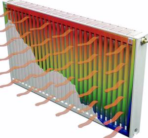
Unfortunately, it is impossible to accurately calculate the pipe cross-section. One way or another, you will have to choose from a couple of options. This point is worth clarifying: a certain amount of heat needs to be delivered to the radiators, while achieving uniform heating of the batteries. If we are talking about systems with forced ventilation, then this is done using pipes, a pump and the coolant itself. All that is needed is to drive the required amount of coolant over a certain period of time.
It turns out that you can choose pipes of a smaller diameter and supply the coolant at a higher speed. You can also make a choice in favor of pipes of a larger cross-section, but reduce the intensity of the coolant supply. The first option is preferable.
The influence of temperature on the properties of the coolant
In addition to the factors described above, the temperature of the water in the heating pipes affects its properties. This is the basis of the operating principle of gravity heating systems. As the heating level of water increases, it expands and circulation occurs.
Coolants for heating systems
However, if antifreeze is used, exceeding the normal temperature in the radiators can lead to different results. Therefore, for heating with a coolant other than water, you should first find out the permissible heating rates. This does not apply to the temperature of central heating radiators in the apartment, since such systems do not use antifreeze-based liquids.
Antifreeze is used if there is a possibility that low temperatures will affect radiators. Unlike water, it does not begin to change from a liquid to a crystalline state when it reaches 0°C. However, if the heat supply operation exceeds the norms of the temperature table for heating to a greater extent, the following phenomena may occur:
- Foaming. This entails an increase in the volume of coolant and, as a result, an increase in pressure. The reverse process will not be observed when the antifreeze cools;
- Formation of limescale. Antifreeze contains a certain amount of mineral components. If the heating temperature in the apartment is violated, they begin to precipitate. Over time, this will lead to clogged pipes and radiators;
- Increasing the density index. Malfunctions of the circulation pump may occur if its rated power was not designed for such situations.
Therefore, it is much easier to monitor the water temperature in the heating system of a private home than to control the degree of heating of antifreeze. In addition, when evaporating, ethylene glycol-based compounds emit gas that is harmful to humans. Currently, they are practically not used as a coolant in autonomous heat supply systems.
Before pouring antifreeze into the heating, you should replace all rubber gaskets with paranitic gaskets. This is due to the increased permeability of this type of coolant.
How to check the heating circulation pump for serviceability
You can check in the following ways.
Ease of inclusion
To examine the performance of the equipment, it is recommended to check whether it is easy to turn on. After seasonal downtime, the condition of the unit must be checked.
To do this, it is recommended that after switching on, listen to the sounds that the equipment makes during operation. If there is no damage, the unit operates quietly .
If you hear various sounds, you will have to check the contamination of parts , the amount of water in the system, etc.
Presence of noise during operation
If the circular pump makes noise, it requires diagnostics or complete replacement. Sounds occur due to malfunction of the rotor or impeller , which can render the entire heating system unusable.
Sometimes noise occurs due to voltage drop . This happens due to imbalance and synchronization, which leads to uneven movement of the coolant.
Attention! Diagnostics are carried out only by a specialist .
If operation is stable, but the device still makes noise, it is recommended to check:
- Is the operating power of the unit equal to the initial values? If the calculations are similar, then the coolant moves too quickly or slowly, which leads to noise.
- Is the motor rotor in a horizontal position?
Bearing operation
Bearings wear out and vibrate heavily.
They are responsible for rotating the impeller, so if the part is no longer suitable for use, it needs to be replaced.
Also, bearings sometimes become damaged and make knocking or squeaking noises. To eliminate the problem, disassembly and washing are carried out. A special worker does this.
The design of check valves allows you to maintain the desired speed, pressure and direction of hot water in the pipeline. Their installation is especially relevant in systems with several circuits and pumps. The absence of such valves can lead to slower water movement and disruption of its circulation, so you should not skimp on installing them. The choice of valves of appropriate sizes and degree of elasticity depends on the load and type of heating system.
The causes of water leaks in the system may be poor-quality installation of pipes, damage to connection areas as a result of corrosion or mechanical failures. With an open type piping system, leaks can be easily detected by visual inspection. To identify damage and check the hidden system, it is necessary to involve a specialist.
You can eliminate the leak by tightening and wrapping the loose connection with tow, replacing leaking components, or cutting out and replacing damaged sections of pipes.
Coolant flow in the heating system
The flow rate in the coolant system implies the mass amount of coolant (kg/s) intended to supply the required amount of heat to the heated room. The calculation of the coolant in the heating system is determined as the quotient of dividing the calculated heat demand (W) of the room (rooms) by the heat transfer of 1 kg of heating fluid (J/kg).
Some tips for filling the heating system with coolant in the video:
The coolant flow in the system during the heating season in vertical central heating systems changes, since they are regulated (this is especially true for the gravitational circulation of the coolant - in more detail: “Calculation of the gravitational heating system of a private house - diagram”). In practice, in calculations, coolant flow is usually measured in kg/h.
How is the heating system of an apartment building balanced?
We perform an audit of the heating system with subsequent restoration of heat supply parameters.
One of the main problems when balancing is the lack of exact flow rates for the risers; only data on the total flow rate for the entire apartment building is known. Because the houses were built a long time ago, it is possible that residents will replace heating radiators and make significant changes to the heat supply scheme of the apartment buildings, which will affect consumption.
The result of balancing should be a temperature of the same value at the control points. The return pipeline of each riser should be selected as control points. By the temperature of the return riser, you can understand what the temperature of the battery of the last consumer is.
Purposes of hydraulic calculation
The objectives of hydraulic calculation are as follows:
- Select the optimal pipeline diameters.
- Link pressures in individual branches of the network.
- Select a circulation pump for the heating system.
Let's look at each of these points in more detail.
1.
Selection of pipeline diameters
If the system is branched - there is a short and a long branch, then on the long branch there is a large flow rate, and on the short branch - less. In this case, the short branch should be made from pipes of smaller diameters, and the long branch should be made from pipes of larger diameter.
And, as the flow rate decreases, from the beginning to the end of the branch, the diameters of the pipes should decrease so that the coolant speed is approximately the same.
2.
Linking pressures in individual branches of the network
Linking can be done by selecting the appropriate pipe diameters or, if the possibilities of this method have been exhausted, then by installing pressure flow regulators or control valves on individual branches.
Adjustment fittings may be different.
Budget option - install a control valve - i.e. valve with smooth adjustment, which has a gradation in setting. Each valve has its own characteristics. During hydraulic calculations, the designer looks at what pressure needs to be extinguished, and the so-called pressure discrepancy between the long and short branches is determined. Then, based on the characteristics of the valve, the designer determines how many revolutions this valve will need to open from the fully closed position. For example, by 1, 1.5 or 2 turns. Depending on the degree of opening of the valve, different resistance will be added.
A more expensive and complex version of control valves is the so-called. pressure regulators and flow regulators. These are devices on which we set the required flow rate or the required pressure drop, i.e. pressure drop on this branch. In this case, the devices themselves control the operation of the system and, if the flow does not meet the required level, they open the cross-section and the flow increases. If the flow rate is too high, the cross section is blocked. The same thing happens with pressure.
If all consumers, after an overnight decrease in heat transfer, simultaneously opened their heating appliances in the morning, then the coolant will try, first of all, to flow to the appliances closest to the heating point, and will reach the furthest ones after hours. Then the pressure regulator will work, covering the nearest branches and thereby ensuring a uniform supply of coolant to all branches.
3.
Selection of a circulation pump by pressure (pressure) and flow (supply)
If there are several circulation pumps in the system, then if they are installed in series, their pressure will be summed up, and the flow rate will be total. If the pumps operate in parallel, then their flow rate is summed up, and the pressure will be the same.
Important: Having determined the pressure loss in the system during the hydraulic calculation, you can select a circulation pump that will optimally match the parameters of the system, ensuring optimal costs - capital (cost of the pump) and operating (cost of electricity for circulation)
Optimal values in an individual heating system
Autonomous heating helps to avoid many problems that arise with a centralized network, and the optimal temperature of the coolant can be adjusted according to the season.
In the case of individual heating, the concept of standards includes the heat transfer of a heating device per unit area of the room where this device is located. The thermal regime in this situation is ensured by the design features of the heating devices. It is important to ensure that the coolant in the network does not cool below 70 °C. 80 °C is considered optimal
With a gas boiler, it is easier to control heating, because manufacturers limit the ability to heat the coolant to 90 °C. Using sensors to regulate the gas supply, the heating of the coolant can be adjusted.
It is a little more difficult with solid fuel devices; they do not regulate the heating of the liquid, and can easily turn it into steam. And it is impossible to reduce the heat from coal or wood by turning the knob in such a situation. Control of heating of the coolant is quite conditional with high errors and is carried out by rotary thermostats and mechanical dampers.
Electric boilers allow you to smoothly regulate the heating of the coolant from 30 to 90 °C. They are equipped with an excellent overheat protection system.
Coordination of water temperature in the boiler and system
There are two options for how you can coordinate high-temperature coolants in the boiler and lower-temperature coolants in the heating system:
- In the first case, the efficiency of the boiler’s operation should be neglected and, at its outlet, the coolant should be supplied to the degree of heating that the system currently requires. This is what they do in small boiler houses. But in the end, it turns out that the coolant is not always supplied in accordance with the optimal temperature conditions according to the schedule (read: “Schedule of the heating season - beginning and end of the season”). Recently, more and more often in small boiler houses, a water heating regulator is installed at the outlet, taking into account the readings, which records the coolant temperature sensor.
- In the second case, the heating of water for transportation through networks at the exit from the boiler room is maximized. Then, in the immediate vicinity of consumers, the temperature of the coolant is automatically adjusted to the required values. This method is considered more progressive; it is used in many large heating networks, and since regulators and sensors have become cheaper, it is increasingly used in small heating supply facilities.

Stages of designing heating systems
Hydraulic calculations together with thermal calculations are considered one of the basic ones in the process of creating an efficient intra-house heating system. The main task of hydraulic calculation is to ensure that the calculated costs correspond to its actual performance indicators. The volume of coolant circulating in the network must form a stable thermal balance, ensuring the required sanitary temperature inside the building.
The hydraulic calculation of a heating system consists of a system of calculations that can establish the important characteristics of the heating network:
- The minimum permissible internal diameters of pipes and the volume of coolant that the selected range and standard size of pipelines can pass through;
- all hydraulic losses in the calculated areas;
- hydromechanical adjustment conditions;
- total water pressure loss;
- optimized water volume.
In accordance with the obtained calculation data, electric pumps and standard sizes of forward and return pipes are selected.
Temperature standards
- DBN (V. 2.5-39 Heat networks);
- SNiP 2.04.05 “Heating, ventilation and air conditioning.”
For the calculated supply water temperature, the figure is taken that is equal to the water temperature at the outlet of the boiler, according to its passport data.
For individual heating, deciding what the coolant temperature should be should take into account the following factors:
- 1 Beginning and ending of the heating season based on the average daily outdoor temperature of +8 °C for 3 days;
- 2 The average temperature inside heated premises of housing, communal and public importance should be 20 °C, and for industrial buildings 16 °C;
- 3 The average design temperature must comply with the requirements of DBN V.2.2-10, DBN V.2.2.-4, DSanPiN 5.5.2.008, SP No. 3231-85.
According to SNiP 2.04.05 “Heating, ventilation and air conditioning” (clause 3.20), the coolant limit values are as follows:
- 1 For a hospital – 85 °C (excluding psychiatric and drug departments, as well as administrative or household premises);
- 2 For residential, public, and domestic buildings (not counting halls for sports, trade, spectators and passengers) – 90 °C;
- 3 For auditoriums, restaurants and premises for production of categories A and B – 105 °C;
- 4 For catering establishments (excluding restaurants) – this is 115 °C;
- 5 For production premises (categories B, D and D), where flammable dust and aerosols are emitted – 130 °C;
- 6 For staircases, lobbies, pedestrian crossings, technical premises, residential buildings, production premises without the presence of flammable dust and aerosols – 150 °C.
Depending on external factors, the water temperature in the heating system can be from 30 to 90 °C. When heated above 90 °C, dust and paintwork begin to decompose. For these reasons, sanitary standards prohibit greater heating.
To calculate optimal indicators, special graphs and tables can be used, which define standards depending on the season:
- With an average reading outside the window of 0 °C, the supply for radiators with different wiring is set at 40 to 45 °C, and the return temperature at 35 to 38 °C;
- At -20 °C, the supply is heated from 67 to 77 °C, and the return rate should be from 53 to 55 °C;
- At -40 °C outside the window, all heating devices are set to the maximum permissible values. On the supply side it is from 95 to 105 °C, and on the return side it is 70 °C.
Heating system wiring diagram and heating pipe diameter
The heating wiring diagram is always taken into account. It can be two-pipe vertical, two-pipe horizontal and single-pipe. A two-pipe system involves both upper and lower placement of lines. But the single-pipe system takes into account the economical use of the length of the lines, and is suitable for heating with natural circulation. Then the two-pipe system will require the mandatory inclusion of a pump in the circuit.
There are three types of horizontal wiring:
- Dead end;
- Beam or collector;
- With parallel movement of water.
By the way, in the diagram of a single-pipe system there may also be a so-called bypass pipe. It will become an additional line for fluid circulation if one or more radiators are turned off. Usually, shut-off valves are installed on every radiator, which allow you to shut off the water supply if necessary.
Selecting a Key Contour
The hydraulic arrow separates the boiler and heating circuits
Here we need to consider two schemes separately - one-pipe and two-pipe. In the first option, the calculation must be carried out through the most loaded riser, where a decent number of radiators and shut-off valves are installed.
In another option, the busiest circuit is selected. Actually, it is based on this that calculations need to be made. All other circuits will have much less hydraulic resistance.
For example, if a horizontal pipe junction is considered, then the busiest ring of the basement is selected. By load they know the heat load.
Coolant speed
Schematic calculation
There is a minimum speed of hot water inside the heating system at which the heating itself operates optimally. This is 0.2-0.25 m/s. If it decreases, then air begins to be released from the water, which leads to the formation of air jams. Consequences - the heating will not work and the boiler will boil.
This is the lower threshold, and as for the upper level, it should not exceed 1.5 m/s. Exceeding it threatens the appearance of noise inside the pipeline. The most acceptable indicator is 0.3-0.7 m/s.
If you need to accurately calculate the speed of water movement, you will have to take into account the parameters of the material from which the pipes are made. Especially in this case, the roughness of the internal surfaces of the pipes is taken into account.
For example, hot water moves through steel pipes at a speed of 0.25-0.5 m/s, through copper pipes 0.25-0.7 m/s, through plastic pipes 0.3-0.7 m/s.
Operating principle of heating controllers
The temperature regulator of the coolant circulating in the heating system is a device that provides automatic control and adjustment of water temperature parameters.
This device, shown in the photo, consists of the following elements:
- computing and switching node;
- working mechanism on the hot coolant supply pipe;
- an executive unit designed to mix in the coolant coming from the return. In some cases, a three-way valve is installed;
- booster pump at the supply section;
- The booster pump is not always in the “cold bypass” section;
- sensor on the coolant supply line;
- valves and shut-off valves;
- return sensor;
- outside air temperature sensor;
- several room temperature sensors.
Now you need to understand how the coolant temperature is regulated and how the regulator functions.
At the outlet of the heating system (return), the temperature of the coolant depends on the volume of water passing through it, since the load is a relatively constant value. By covering the liquid supply, the regulator thereby increases the difference between the supply and return lines to the required value (sensors are installed on these pipelines).
When, on the contrary, it is necessary to increase the coolant flow, then a booster pump is installed into the heating system, which is also controlled by the regulator. In order to lower the temperature of the incoming water flow, a cold bypass is used, which means that part of the coolant that has already circulated through the system is again directed to the inlet.
As a result, the regulator, redistributing coolant flows depending on the data recorded by the sensor, ensures compliance with the temperature schedule of the heating system.
Often such a regulator is combined with a hot water supply regulator using one computing node. The device that regulates DHW is easier to operate and in terms of actuators. Using a sensor on the hot water supply line, the passage of water through the boiler is adjusted and, as a result, it consistently has the standard 50 degrees (read: “Heating through a water heater”).
Pump design elements
In order for the operation of the circulation pump to be problem-free, it is necessary to regularly check the condition of the equipment. A preventive inspection will help identify negative factors that can lead to serious breakdowns in the future. Their timely elimination will allow you to avoid force majeure situations and complex repair procedures.
A standard inspection includes a few simple steps:
- checking the tightness of connections. It is necessary to carefully inspect all fittings with which the pump is attached to the heating system. Some types of connecting elements may become loose over time and must be tightened. In addition, problems may arise with the destruction of the thread or seal - in this case, you need to unscrew the fitting, cut additional turns or wind a new layer of FUM tape, and then reassemble the element;
- adding lubricant. There are bearings inside the device that must be well lubricated. Otherwise, they will work worse, which will lead to overheating of the device;
- cleaning the filter. The mesh element gradually becomes clogged with dirt, even if you use a very high-quality coolant. Therefore, it is necessary to promptly remove rust and scale particles stuck in the filter.
Actually, this is a basic set of actions that need to be performed for prevention. In addition, you should follow some rules for operating the circulation pump:
- Avoid dry running. The pump should only be turned on if the required amount of coolant is present in the heating system. Equipment running “dry” will burn out very quickly, and may even drag down some other electrical appliances;
- Avoid prolonged idle time. In many regions, the heating system operates in seasonal mode - from September to May. It is clear that there is no point in launching it in thirty-degree heat. But if left idle for such a long time, some elements of the circulation pump may fail. Therefore, it must be turned on at least once a month for a quarter of an hour. Agree, it takes a little time, but it will help to avoid possible problems in the future;
- initially purchase a pump whose characteristics fully correspond to the needs of your heating system. It happens that owners, in an attempt to save money, buy a low-power device and try to use it in a system with a large volume of coolant. As a result, the device constantly works at the limit of its capabilities and, of course, fails very quickly. That is why it is important to make advance calculations of the parameters that you should focus on when purchasing. You can find information on how to do this on our portal;
- provide for overheating and “dry running” sensors. These regulators are not available on all models, but it is advisable to find and purchase a device with them. You may not immediately notice the problem on your own. For example, if there is a coolant leak in the system, then until you detect it, the pump will run idle and may simply burn out. And the sensor will react instantly, automatically turning off the equipment, and thereby preventing breakdown.
Recommendations for selection and operation
When choosing a coolant for a heating system, it is worth knowing that not all heating systems are capable of working with antifreeze. Many manufacturers do not allow the possibility of using it as a coolant; this often serves as a reason for refusing warranty service for the equipment.
Before filling the heating system with coolant, you need to carefully study its features, such as:
- composition, purpose and types of additives;
- freezing point;
- duration of operation without replacement;
- interaction of antifreeze with rubber, plastic, metal, etc.;
- harmlessness to health and environmental safety (replacing the coolant in the system will require draining it).
A surface tension coefficient lower than that of water gives it fluidity and allows it to easily penetrate into pores and microcracks. All connections must be sealed with Teflon, paronite or resistant rubber gaskets. It makes no sense to use zinc-coated elements in the heating system. As a result of a chemical reaction, it will be destroyed during the first heating season.
The calculation shows that due to its low heat capacity, antifreeze accumulates and releases heat energy more slowly, so it is necessary to use pipes with an increased diameter and increase the number of radiator sections. The circulation of coolant in the system is hampered by the increased viscosity of antifreeze, which reduces efficiency. This can be eliminated by replacing the pump with a more powerful one.
A preliminary calculation will help to correctly design the heating circuit and will allow you to find out the required volume of coolant in the system.
It is unacceptable to exceed the temperature of the coolant in the heating system more than that declared by the manufacturer. Even a short-term increased temperature of the coolant worsens its parameters, leads to the disintegration of additives and the appearance of insoluble formations in the form of sediment and acids. When sediment gets on the heating elements, carbon deposits form. Acids, when reacting with metals, contribute to the formation of corrosion.
The service life of antifreeze depends solely on the selected mode and is 3-5 years (up to 10 seasons). Before replacing it, it is necessary to flush the entire system and boiler with water.
Expansion tank calculation
To calculate an expansion tank for a closed heating system, it is necessary to find out how much the volume of liquid increases when it is heated from room temperature +20 ºС to operating temperature, which is in the range of 50-80 ºС. This task is also not an easy one, but it can be solved in another way.
It is considered quite correct to take the volume of the tank as a tenth of the total amount of water in the system, including radiators and the water jacket of the boiler. Therefore, we open the equipment passports again and find in them the capacity of 1 section of the battery and the boiler tank.
Next, the calculation of the volume of coolant in the heating system is carried out according to a simple scheme: the cross-sectional area of a pipe of each diameter is calculated and multiplied by its length. The obtained values are summed up, passport data is added to them, and then a tenth of the result is taken. That is, if there are 150 liters of water in the entire system, then the capacity of the expansion tank should be 15 liters.