Essential elements
The thermal unit consists of a set of devices and metering devices that provide the performance of one or several functions at the same time: storage, accumulation, measurement, display of information about mass (volume), amount of thermal energy, pressure, temperature of the circulating fluid, as well as operating time .
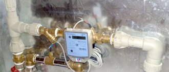
As a rule, a heat meter is used as a metering device, which includes a resistance thermal converter, a heat calculator and a primary flow converter. Additionally, the heat meter can be equipped with filters and pressure sensors (depending on the model of the primary converter). Heat meters can use primary transducers with the following measurement options: vortex, ultrasonic, electromagnetic and tachometer.
Technical accounting systems for water consumption
Like everyone else, there are two types of technical accounting systems for water consumption: automated systems for technical accounting of drinking, technical and waste water (ASTUV) and automated systems for commercial accounting of drinking, technical and waste water (ASKUV).
The water metering system is a multi-level automated system that operates in real time and carries out commercial accounting of water consumption. The number of levels and the architecture of the system are determined at the stage of development of the technical specifications and depend on the complexity and water supply system of the facility.
The objectives of the water metering system include:
- Automated accounting of water flow, temperature and pressure in pipelines;
- Automatic collection of information from all water meters and controllers;
- Processing and statistical analysis of the obtained data;
- Collection of data on the condition of measuring instruments;
- Remote automatic diagnostics of the state of technological equipment;
- Warning alarm in case of violation of water consumption regimes, abnormal operation of equipment, unauthorized intervention in the operation of equipment;
- Generation of protection and blocking signals in case of emergency situations;
- Generation of reporting documents.
The water metering system allows you to analyze data on:
- The amount of drinking, technical and waste water supplied (received) for a certain period and its parameters;
- The total time of accumulation of the volume and mass of water in each pipeline;
- Technical condition of the equipment;
- Technical condition of engineering networks;
- Unauthorized access to metering devices.
To measure water consumption, the following types of meters are used: tachometer, electromagnetic, ultrasonic, vortex.
Installation of UUTE
To install a heat metering unit, you need to follow certain instructions:
- Depending on the form of management of the apartment building, a meeting is held to authorize the work and agree on the procedure for payments (targeted spending of funds).
- Initially, calculation processes are carried out. The procedures are performed by specialists who design heat supply facilities. Only after drawing up the technical documentation can you move on to the next stage.
- An application for approval of the work is submitted to the heat supply organization. The company cannot refuse installation without legitimate reasons.
- After clarifying the nuances and obtaining permission, installation is carried out according to the approved scheme. The equipment is programmed and configured.
- A commission from the heat supply organization checks the performance of the heating unit and adopts a system for commercial accounting of resource consumption.
All devices must be placed so as to ensure ease of monitoring, removal and debugging.
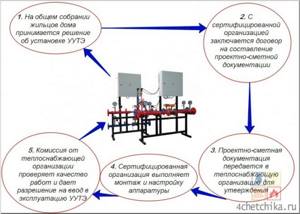
Drawing up design estimates, installation and configuration of equipment must be carried out by an organization that has a certificate and permission to perform such work, otherwise the selection committee will not give permission to put the UUTE into operation
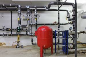
Design and principle of operation of a heating elevator
At the entry point of the heating network pipeline, usually in the basement, a node that connects the supply and return pipes catches your eye. This is an elevator - a mixing unit for heating a house. The elevator is manufactured in the form of a cast iron or steel structure equipped with three flanges. This is an ordinary heating elevator; its operating principle is based on the laws of physics. Inside the elevator there is a nozzle, a receiving chamber, a mixing neck and a diffuser. The receiving chamber is connected to the “return” using a flange.
Superheated water enters the elevator inlet and passes into the nozzle. Due to the narrowing of the nozzle, the flow speed increases and the pressure decreases (Bernoulli's law). Water from the return line is sucked into the area of low pressure and mixed in the mixing chamber of the elevator. The water reduces the temperature to the desired level and at the same time the pressure decreases. The elevator operates simultaneously as a circulation pump and mixer. This is briefly the principle of operation of an elevator in the heating system of a building or structure.
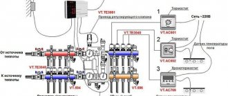
Thermal unit diagram
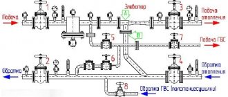
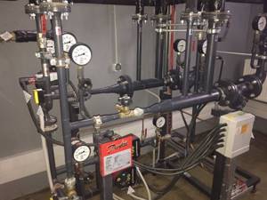
Adjustment of the coolant supply is carried out by the elevator heating units of the house. The elevator is the main element of the heating unit and needs piping. The control equipment is sensitive to contamination, so the piping includes dirt filters that are connected to the “supply” and “return”.
The elevator harness includes:
- mud filters;
- pressure gauges (inlet and outlet);
- temperature sensors (thermometers at the elevator inlet, outlet and return);
- valves (for preventive or emergency work).
This is the simplest circuit option for adjusting the temperature of the coolant, but it is often used as the basic device of a thermal unit. The basic elevator heating unit for any buildings and structures provides regulation of the temperature and pressure of the coolant in the circuit.
The advantages of using it for heating large objects, houses and high-rise buildings:
- reliability due to the simplicity of the design;
- low cost of installation and components;
- absolute energy independence;
- significant savings in coolant consumption up to 30%.
But while there are undeniable advantages of using an elevator for heating systems, the disadvantages of using this device should also be noted:
- the calculation is done individually for each system;
- a mandatory pressure drop is required in the heating system of the facility;
- if the elevator is unregulated, then it is impossible to change the parameters of the heating circuit.
Elevator with automatic adjustment
Currently, elevator designs have been created in which the nozzle cross-section can be changed using electronic adjustment. This elevator has a mechanism that moves the throttle needle. It changes the lumen of the nozzle and as a result the coolant flow changes. Changing the lumen changes the speed of water movement. As a result, the mixing ratio of hot water and water from the “return” changes, thereby achieving a change in the temperature of the coolant in the “supply”. Now it’s clear why water pressure is needed in a heating system.
The elevator regulates the flow and pressure of the coolant, and its pressure drives the flow in the heating circuit.
Why do you need a thermal unit?
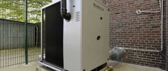
Heating unit photo
The heating unit is located at the entrance of the heating main to the house. Its main purpose is to change the parameters of the coolant.
To put it more clearly, the heating unit reduces the temperature and pressure of the coolant before it enters your radiator or convector.
This is necessary not only so that you do not get burned from touching the heating device, but also to extend the service life of all heating system equipment.
This is especially important if the heating inside the house is installed using polypropylene or metal-plastic pipes.
There are regulated operating modes of thermal units:
- 150/70
- 130/70
- 110/70
These figures show the maximum and minimum temperature of the coolant in the heating main.
Also, according to modern requirements, a heat meter must be installed at each heating unit. Now let's move on to the design of thermal units.
Economic efficiency from ITP automation
When designing an ITP, in addition to the requirements of SNiP, the designer must be guided by the technical conditions for the heat supply of the facility with clear data on hydraulic parameters and temperature schedules. Regardless of the manufacturer, automatic control systems may include a set of regulators with sensors, shut-off and control and mixing valves, pumps, automation and control cabinets, instrumentation, and other fittings. One controller controls heating and hot water systems where necessary.
Let's consider the use of temperature controllers in residential buildings. When calculating the economic efficiency of using a heating temperature controller with a regulating hydraulic elevator for a 108-apartment building, the savings are 11%; installation of the equipment pays off in 0.78 years. Only one factor was used in the calculation - excessive heat consumption due to autumn-spring floods. If the second circuit of the control system is used to regulate thermal energy for heating hot water, the economic effect will increase even more.
Economic indicators of the heating and hot water control system: total savings are more than 15%, payback from the implementation of the control system is less than 0.5 years.
Calculations show that for buildings with 80 or more apartments, the costs of introducing automatic control systems pay off in less than 1 year. At facilities where the unit costs of energy-saving equipment and its installation are 1 Gcal higher, the payback period increases, for example, when the number of apartments is less than 80 or at small social facilities. Let's take a kindergarten as an example. The automatic heating control system includes a regulating hydraulic elevator and a microprocessor control unit based on signals from temperature sensors. The payback period for the project is 0.94 years. Advantages of this scheme:
– high reliability and trouble-free operation even in the event of a temporary power failure, because the elevator also performs the function of a pump; – the possibility of introducing a flexible control schedule, taking into account night time, weekends and holidays for the entire heating season; – optimization of temperature comfort in the premises due to the possibility of setting a preliminary heating before working hours; – mandatory monitoring of return coolant parameters.
If a similar facility has hot water preparation and installs a flow regulator for DHW, then the unit costs for automation of the heat station will be lower: the same electronic unit is used, a hot water temperature sensor is added to it, and a shut-off and control valve is additionally used for DHW. The economic effect increases to 30% with a payback of 0.72 years.
We verify all technical and economic calculations, especially when introducing new design solutions, using special monitoring tools and commercial instrument metering data.
In conclusion, I would like to note that saving fuel and energy resources through the use of automatic program control systems for heat consumption is feasible and economically justified. There is no alternative to this process.
You can purchase a wide range of modern automation equipment at competitive prices in our company store.
Currently, the share of payment for HEATING is the largest line in the receipt for utility bills. In this regard, many owners are interested in the possibility of reducing these costs.
One way to do this is to equip the home heating system with an automatic ITP (weather controller). The weather control system for heating is justified only if a heat meter (thermal energy metering unit) is already installed in the house.
It is difficult for power engineers to comply with the temperature schedule (temperatures on the supply and return heating pipelines depending on the outside air temperature). Their goal is to provide as much heat as possible to consumers, so that all houses located in the area around the central heating point (nearest and remote) have enough temperature. Also, at the central heating station, the coolant parameters do not change reciprocally depending on the time of day (sunny day, night, day of the week, etc.)
Connection diagrams
The elevator unit can be used in systems with various specific features - single-pipe, autonomous or other heat supply lines. The principles of coolant supply and flow parameters do not always allow for a constant and stable output result. To organize normal heat supply to apartments or adjust the flow parameters coming from the main network, various connection schemes for elevator units are used. All of them require additional equipment, sometimes in quite large quantities, but the result achieved as a result of this compensates for the costs incurred. Let's look at the existing connection diagrams:
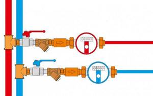
With water flow regulator
Water consumption is the main factor that makes it possible to adjust the heating mode of the premises. Changes in flow cause temperature fluctuations in living rooms, which is unacceptable. The issue is resolved by installing a regulator in front of the mixing unit, which ensures constant water flow and stabilizes the thermal regime.
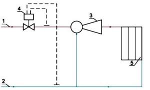
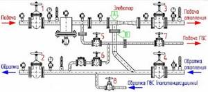
Diagram of an elevator mixing unit with a flow regulator: 1 - supply line of the heating network; 2 - return line of the heating network; 3 - elevator; 4 - flow regulator; 5 - local heating system
This solution becomes especially important in single-pipe systems, where there is a load in the form of hot water supply, which destabilizes the flow of hot water and creates significant fluctuations during active water withdrawal (morning and evening hours, holidays and weekends). At the same time, this scheme is not able to correct the situation when the temperature of the coolant in the main line changes, which is its drawback, although not too significant. A drop in coolant temperature in the supply pipelines means an accident at a thermal power plant or other heating point, and this rarely happens.
With regulating nozzle
The connection diagram of the elevator unit with the ability to adjust the nozzle capacity allows you to quickly respond to changes in coolant parameters in the main line.
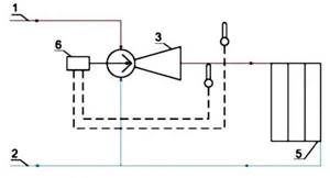
Diagram of an elevator unit with a regulating needle: 1 - supply line of the heating network; 2 - return line of the heating network; 3 - elevator; 5 - local heating system; 6 - regulator with a needle pushed into the elevator nozzle
At the same time, manual adjustment is ineffective, since for this you need to constantly approach the elevator, which is usually located in the basement. The greatest efficiency of a system with an adjustable nozzle is achieved with complete automation of the process, using temperature and pressure sensors that send a signal to the elevator servo drive. This scheme allows you to gain additional opportunities when setting the operating mode, but the need for it does not always arise, but only in overloaded or unstable systems with possible fluctuations in coolant temperature.
Diagram of an elevator unit using temperature and pressure sensors that send a signal to the elevator servo drive
The disadvantages of such schemes include the need to initially ensure high pressure in the system, since adjustment is possible only within the limits of the flow parameters in the line. In addition, loads on the mechanics, in particular on the nozzle and needle, create the need for constant monitoring and timely replacement of failed elements.
With control pump
Such schemes are used in the absence of sufficient pressure in the supply pipelines for the operation of the elevator.
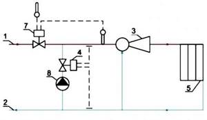
Diagram of an elevator unit with a correction pump: 1 - supply line of the heating network; 2 - return line of the heating network; 3 - elevator; 4 - flow regulator; 5 - local heating system; 7 — temperature controller; 8 - mixing pump
An increase in pressure makes it possible to use an elevator unit in the autonomous heating networks of a private house and allows for circulation of the coolant when the pressure in the main disappears. The pump is installed in front of the elevator or on the jumper between the forward and return pipelines before entering the elevator. To ensure normal operation, a temperature controller must be used in addition to the pump, and a power supply must be connected.
Hot water supply in heating systems
DHW in multi-storey buildings is usually centralized, with water heated in boiler rooms. Hot water supply is connected from heating circuits, both single-pipe and double-pipe. The temperature in the hot water tap in the morning can be warm or cold, depending on the number of main pipes. If there is a single-pipe heating supply to an apartment building with a height of 5 floors, then when you open a hot tap, cold water will flow out of it first within half a minute.
The reason lies in the fact that at night, rarely do any residents turn on the hot water tap, and the coolant in the pipes cools down. As a result, there is an overconsumption of unnecessary cooled water, since it is drained directly into the sewer.
Unlike a single-pipe system, in a two-pipe version, hot water circulates continuously, so the above-described problem with hot water does not arise there. True, in some houses, a riser with pipes is looped through the hot water supply system - heated towel rails, which are hot even in the summer heat.
In the summer, the entire system that provides central heating in an apartment building is tested. Utility services carry out routine and major repairs on the heating main, while disconnecting certain sections of it. On the eve of the upcoming heating season, the repaired heating main is re-tested (for more details: “Rules for preparing a residential building for the heating season”).
Features of heat supply in an apartment building, details in the video:
Schemes of metering units
Several options for creating a system of heating points are popular. Hot water connection diagrams:
- Sequential two-stage. A classic solution in which there is a division into two sections. The first is the inlet pipe of the heating system, and the second is the return pipe. The convenience of the scheme is that there is no need for network water. There are a number of significant disadvantages, among which is the need to implement an automated control system to properly distribute heat.
- Parallel single stage. Standard option, characterized by simplicity. The main problem is the significant consumption of network water, which is used to create a water supply. Connection principle: hot water supply pipes are connected in parallel to the heating system.
- Mixed two-stage. A universal solution that allows you to quickly make the necessary settings. Unlike the previous version, there is a serial connection, and the implementation principle is almost identical to the first version.
Much depends on the characteristics of the apartment building and the functioning heating system.
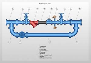
Composition and location
Apartment buildings can have different configurations. Because of this, the UUTs may be different in appearance and design from each other.
Such units can also be installed for a private house if it is connected to a central heating system
However, the main elements are included in each node:
- Shut-off and control valves. Devices and devices for regulating and completely shutting down various components of the heating system.
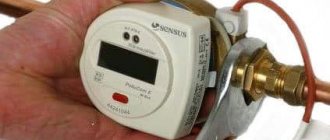
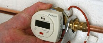
- Heat meter. The main measuring device, which may differ in design, but is required to give readings of the main parameters of heat supply.
- Sump. Garbage collection site. The main purpose of this device is to prevent foreign objects and substances from entering the heating system.
- Flow meter. A device that takes into account coolant flow and helps regulate its supply.
- Elevator. The elevator heating unit serves to regulate the temperature of the coolant. In this device, by mixing hot and cooled coolant (return), adjustment occurs to standard values.
- Thermal sensor. A measuring device for recording the temperature of the coolant when returning from the heating system.
- Auxiliary equipment. Many control centers are provided with additional devices and units. Modern technologies can significantly expand control capabilities.
The main requirement for the arrangement of instruments and all components of the control system is maximum accuracy and efficiency. Therefore, there are certain rules for the sequence and location of the main nodes. Here are just a few of them:
- Place metering devices at the interface, as close as possible to valves and coolant supply regulators.
- Prohibition on the installation of additional pipeline outlets that bypass sensors.
- The temperature sensor on the return line is placed in front of the valve on the outside.
- Place instruments so that there is good visual access for taking instrument readings and servicing them.
This is interesting: the principle of a two-way valve for heating.
Following the basic instructions, it will not be difficult to equip a heating metering unit if you have all the necessary components for its operation.
Features and Specifications
When installed correctly, the elevator unit of the heating system performs circulation and mixing functions. This device has the following advantages:
Built-in electrical installation
Tax authorities do not have the right to classify fixed assets in the appropriate group. This classification must be carried out by the economic operator itself with the help of the authorized statistical body. A permanently connected electrical installation cannot be considered a separate fixed asset. This increases the building's starting value.
Lighting fixtures, sconces and measuring instruments
If the electrical installation is not integrated into the building structure, it can be considered a stand-alone detector. For individual funds, permanent tax offices receive light inside and outside buildings that are not permanently associated with the building. They can be detached without damaging their structure or the building.
- Lack of connection to the electrical network.
- Efficiency.
- Simplicity of design.
Flaws:
- Inability to regulate outlet temperature.
- Accurate calculation and selection is required.
- A pressure difference must be maintained between the return and supply lines.
Areas of application
IHP for heating air in the ventilation system
TP are necessary for proper distribution of heat between consumers. These include:
- Hot water supply. Part of the heat, as hot water is supplied through pipes, is used to heat the bathroom and kitchen.
- Heating systems – maintain a comfortable temperature in residential and public spaces.
- Ventilation system – the air is heated before entering the building.
- Cold water supply does not apply to consumers, but to supply elements. Cold water serves as a regulator.
They install TP for heating, water supply, air conditioning in both old and new buildings.
Equipment and its application
Energy-saving equipment allows you to create systems of various purposes and complexity: single- and double-circuit, with additional functions for controlling pumps or accumulating and processing statistical information about the progress of the regulation process. But behind all this there must be an integrated economic approach, which includes the following parameters: taking into account the mutual influence of objects and heat supply systems, sanitary and hygienic requirements, comfort, reducing operating costs, reliability of heat accounting and saving fuel and energy resources. Automatic control systems include electronic temperature controllers, temperature sensors, electric drives with a pulse stepper motor, control and shut-off valves. The latter includes shut-off control valves, mixing control valves and control hydraulic elevators.
An important role here is played by temperature regulators, through which the control units are controlled. Since 2010, the RT-2010 temperature controller has been produced, which is an updated and improved version of its predecessor RT-2000A and has the additional ability to install an RS485 interface; an actuator for valves and elevators MEP-3500, which differs from its predecessors and competitors not only in design, but also in a set of additional functions.
The scheme with a regulating hydraulic elevator is very common for facilities that receive superheated coolant from a heat source. It is not allowed to be used only in facilities with hydraulic problems where the pressure difference between the supply and return pipelines is less than 6 meters of water column (0.06 MPa). DG elevators provide high-quality regulation due to the displacement of forward and reverse coolant. The regulating elevator does not require the use of an additional pump, since one of its design elements is a jet pump. Therefore, the use of regulating hydraulic elevators, especially at housing and communal services facilities, reduces installation and operating costs and does not lead to emergency situations in the event of power failures. In emergency situations, stopping the pump in the heating system requires urgent measures to prevent the system from freezing. The scheme with a regulating hydraulic elevator does not have this drawback and the costs of the pump are eliminated and the costs of construction and installation work are therefore significantly lower.
For other heating schemes there is a wide range of shut-off and control valves. If, in accordance with the technical conditions at the site, installation of a pump is necessary, the pump can be installed on the return pipeline or jumper. However, this scheme cannot be used at heating points connected to central heating stations (heat supply schedule – 95˚/70˚ C).
The use of shut-off and control valves is most effective in automatic control systems that allow 100% shutoff of the coolant supply. First of all, this is hot water supply.
Open hot water systems are common and difficult to adjust. In our experience, the use of two-way valves does not provide the required parameters for hot water temperature, return coolant temperature and noise level. In view of this, we offer three-way mixing valves KST.
Based on energy-saving equipment, we also produce compact block heating units that combine, to one degree or another, many circuit solutions.
One of the most important areas that has recently become relevant and in demand is dispatching of regulated objects. It is also possible to implement such systems on the basis of the equipment. Temperature controllers RT-2010, RT-2000A have been developed and are widely used, which are equipped with an RS232 (RS485) interface, through which it is possible to remotely control control systems.
Today, on the basis of regulators, dispatch systems have already been installed and launched, including, in addition to regulation (temperature regulators), also metering (heat meters).
The developed actuators of MEP-3500 valves can be equipped with a current output and additional relay outputs for determining the position of the mechanism. This significantly sets this drive apart from its competitors. Installing an RS485 interface in MEP-3500 drives allows them to be included in the general dispatch system along with a temperature controller and a counter. There is already interest in the implementation of such a project from organizations involved in the development of controllers for supervisory control and data collection from objects.
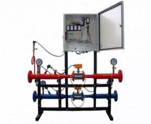
What devices does the energy metering unit consist of?
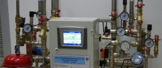
Based on the heat consumption characteristics of a particular facility, the number of metering units can be more or less. All nodes are connected using cable routes that lead from the devices to the computer. The calculator, as a rule, is located in the instrument cabinet; it is used to calculate the amount of thermal energy consumed when recalculating instrument readings.
It is also sometimes equipped with a GPRS transmitter, which, using a cellular network, transmits, upon request (or on a schedule), the readings of all connected devices to the water supplier, and, if the necessary settings are available to the transmitters, to the consumer. As a rule, these readings are verified once a day. This type of data transfer is called dispatching. The consumer can also check the readings at any time by simply opening the cabinet and viewing the data displayed on the electronic display of the computer.
Thermal energy metering unit is not one device, but a complex of devices. Installation of uute is necessary for metering and regulating energy and adjusting the amount of coolant inside. Systems serve to register and control parameters. Installation of this equipment is done in the basement of high-rise buildings on heating pipes.
Main parts of equipment:
- Shut-off valves.
- Sensors for monitoring pressure and temperature in the system.
- Shut-off valves.
- Flow, temperature and pressure transducers.
- Calculator.
The heating unit, the installation of which is initially designed for implementation in the communal systems of apartment buildings, is created using a whole complex of various devices and equipment. Such a device can serve one or several functions, which are:
- Measuring the amount of thermal energy, its pressure, mass, volume and temperature of the liquid that passes through the pipeline during operation.
- Collection and archiving of data on local media.
- Displaying information on metering devices.
Based on the data provided, the functioning of heating equipment in apartment buildings is checked, adjusted and serviced.
A metering device is a device such as a meter, the circuit of which includes:
- Primary flow transducer.
- Heat calculator.
- Resistance thermal converter.
Based on the type of primary transducer used (electromagnetic, tachometer, ultrasonic or vortex measurement option), the heat meter can include filters and pressure sensors in its device.
How to install a heating unit correctly?
Installing a circuit for heat metering equipment in an apartment building implies compliance with the following fundamental requirements during its installation:
- installation of the thermal energy metering equipment circuit must be done only at the boundaries of the balance section of the pipeline in places that are closest to the main valves of the heat source;
- prohibition of taking coolant from the municipal heating system for personal needs;
- adjustment of the average daily and average hourly characteristics of the coolant is done based on the readings of metering devices;
- metering devices must be installed on the return main pipelines and located before the point of connection of the make-up pipeline.
The thermal energy meter must be mounted at the input of heating networks into the ITP room. Before and after the location of the flow meters (at the supply and return) of the metering unit, two control flow meters (or at least fittings for pressure gauges) must be installed. After the inlet pressure gauge, it is necessary to place a special device - a flow meter. Its task is to take into account the volume of coolant passing through a given pipe.
A temperature sensor is installed after the flow meter. As a rule, such a device is not equipped with a special control panel or an arrow that would indicate the temperature, so another control thermometer is installed next to it, which allows you to check the temperature visually.
The location of the heating unit in an apartment building is in the basement, from where heat is supplied to the apartments. In this case, it is connected according to the elevator circuit. It is quite simple and cheap. The main disadvantage of such a system is that it is impossible to make adjustments in the pipes. Because of which some end users may experience some inconvenience. During thaws during the heating season, heat energy is overused.
The main element of this scheme is the elevator. In order to reduce the pressure, a reducer can be installed in front of it. The elevator itself is necessary for mixing the cooled coolant with the hot one. The basis of its operation is the vacuum created at the output. Thanks to it, the coolant in the elevator is under lower pressure, which is why mixing occurs.
But there is another scheme for installing the system. Its operating principle is based on a heat exchanger. Due to the fact that the heating point is connected through this heat exchanger, the coolant in the house and in the heating main is separated. Thanks to this, it becomes possible to carry out its preparation. For this purpose, filtration and additives are used.
Thanks to this scheme, it becomes possible to regulate the temperature and pressure of the coolant in the pipes. Why is this so important? This scheme makes it possible to reduce heating costs.
If we consider the addition of coolant, this sample shows that it is carried out using thermostatic valves. One of the positive aspects is the possibility of using thermostatic valves, and the ability for consumers to use aluminum batteries. But there is a small nuisance - if low-quality coolant is used, the battery life is reduced. Naturally, there is no such possibility as quality control of the coolant.
Important! After connecting the DHW through the heat exchanger, you can control the pressure and temperature of the coolant.
Installation procedure for UUTE
- The first thing the installation process begins with is an inspection of the object followed by the creation of a project. It must be agreed upon with the heat supply organization, in accordance with the norms and regulations of SNiP.
The project includes:
Carrying out calculations regarding installation.
- A selection of high-quality and reliable equipment included in the design.
- Drawing up an estimate.
- The procedure and diagram for installing the structure.
- Insertion of devices into the pipeline, such as shut-off valves, modules.
Using modules on a jumper
When operating appliances on adjacent networks and across the bridge, the consumer regularly submits a report on energy use to the supplier. The method of transfer (electronic, on paper or by automatic reading) is indicated in the contract. The user requires, and the supplier is obliged to provide, a calculation of the volume of heat or media consumed during the reporting period (15 working days after submission of the report).
If the owner of the unit is the heat supplier, then the user can request a printout of the readings taken from the device and characterizing the use of the product for the last period. In case of doubt, any party initiates an audit with the involvement of a commission, about which an audit report is drawn up. If the testimony is found to be correct, then the doubting party bears the financial expenses. In case of incorrect operation of the meter, responsibility is shifted to the owner of the device.

The consumer must regularly submit a report on energy use to the supplier
In the latter case, a calculation method is used to determine the amount of payment. To do this, use the data read in the module’s archive, and if there is none, then take the latest readings. The owner of metering devices is obliged to provide during the operational period:
- access to measuring modules to the second party to the agreement;
- safety of installed registration means;
- integrity of seals on devices and all sensors included in the kit.