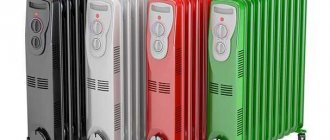
Physical Basics
Cavitation is the formation of steam in a mass of water with a slow decrease in pressure and high speed.
Vapor bubbles can arise under the influence of a sound wave of a certain frequency or radiation from a coherent light source.
In the process of mixing steam voids with water under pressure, it leads to the spontaneous collapse of bubbles and the occurrence of water movement of impact force (it is written about the calculation of hydraulic shock in pipelines).
Under such conditions, molecules of dissolved gases are released into the resulting cavities.
As the cavitation process progresses, the temperature inside the bubbles rises to 1200 degrees.
This negatively affects the materials of water tanks, since oxygen at such temperatures begins to intensively oxidize the material.
Experiments have shown that under such conditions even alloys of precious metals are subject to destruction.
Making a cavitation generator yourself is quite simple. The well-studied technology has been embodied in materials and used for space heating for several years.
In Russia, the first device was patented in 2013.
The generator was a closed container through which water was supplied under pressure. Vapor bubbles are formed under the influence of an alternating electromagnetic field.
What do you know about polypropylene pipes for cold and hot water supply? In this useful article, read about how they differ, as well as the advantages of some and the disadvantages of others.
Read reviews of dishwasher detergents on this page.
Vortex damper
Yes, we will make a device with such a mysterious name - a vortex damper. It will consist of plates arranged lengthwise, placed inside both rings.
Let's see what we need for the job.
- Welding.
- Turbinka.
- Sheet of steel.
- Pipe with thick walls.
The pipe should be smaller than the heat generator. We make two rings out of it, about 5 cm each. We cut several strips of the same size from the sheet. Their length should be 1/4 of the length of the device body, and their width should be such that after assembly there is free space inside.
- We insert the plate into the vice, hang metal rings on one end of it and weld them to the plate.
- We take the plate out of the clamp and turn it the other way. We take the second plate and place it in the rings so that both plates are placed parallel. We fasten all the remaining plates in the same way.
- We assemble the vortex generator with our own hands, and install the resulting structure opposite the nozzle.
Note that the scope for improving the device is almost limitless. For example, instead of the above plates, we can use steel wire, first twisting it into a ball. In addition, we can make holes in plates of various sizes. Of course, none of this is mentioned anywhere, but who says you can't use these improvements?
Finally
And as a conclusion, here are some practical tips. Firstly, it is advisable to protect all surfaces by painting. Secondly, all internal parts should be made of thick materials, since it (the parts) will constantly be in a fairly aggressive environment. And thirdly, take care of several spare caps that have different hole sizes. In the future, you will select the required diameter in order to achieve maximum performance of the device.
This seemingly simple device will allow you to forget about the usual expensive heating
Have you noticed that the price of heating and hot water supply has increased and you don’t know what to do about it? The solution to the problem of expensive energy resources is a vortex heat generator. I will talk about how a vortex heat generator works and what is the principle of its operation. You will also find out whether it is possible to assemble such a device with your own hands and how to do it in a home workshop.
Operating principles
The work process takes place simultaneously in two environmental phases:
- liquids,
- pair.
Pumping devices are not designed to operate in such conditions, which leads to the collapse of cavities with loss of efficiency.
Heat generators mix the phases, causing thermal conversion.
Heaters for domestic use convert mechanical energy into thermal energy with the liquid returning to the source (read about an indirect heating boiler with recirculation on this page).
Do you know about wall-hung toilets for the disabled? Read this useful article about which plumbing fixtures to buy and how to install them for people with disabilities.
What to add to the washing machine to remove scale is written.
The page: https://ru-canalizator.com/kanalizatsiya/vygrebnaya-yama/zhiroulovitel.html describes the installation of grease traps on sewers.
Due to this, heat losses are minimal, within one percent, so losses are taken into account as an error in energy conversion.
Industrial installations operate on a different principle.
The heat output is transferred to a fluid in another device, the power being greater than the mechanical energy of the heater.
This approach is more productive than that of return devices. The devices do not require constant monitoring and configuration.
Several types of similar heat generators are used:
- Griggs rotary generator.
The operation of the device is based on the operation of a centrifugal pump.The apparatus includes: pipes, stator, housing, working chamber.
Several models of rotary converters are manufactured, but the Griggs model is considered the most effective.
ATTENTION! When testing the generator, monitor the pressure gauges.
The difference in inlet and outlet pressure should be 8-12 atmospheres.
The pressure is regulated by a special valve.
The rotor and stator are located so that there is a gap between them, due to which the liquid is heated.
The movement of liquid on the surface of the disk increases the temperature.
The rotor rotation speed can reach 3000 rpm, which is enough to heat the liquid to 90 degrees.
- static generator. The device contains no moving parts.
The formation and collapse of steam bubbles takes place in nozzles that are connected to the working container.Pressure is created by a conventional circulation pump to increase water pressure.
High fluid speed is ensured by different diameters at the inlet and outlet of the nozzle.
The efficiency of static devices is lower than that of rotary devices. They take up a significant area and weigh more.
FOR YOUR INFORMATION.
Due to the absence of moving mechanisms, static generators last longer, do not require fine tuning, and replacing nozzles requires minimal costs.
Cavitation problems of pumps in oil refining
Section: Technology
Cavitation as a physical phenomenon is a violation of the continuity of fluid flow, which occurs in those sections of the flow where the pressure, decreasing, reaches a certain critical value.
Fundamental scientific research into cavitation phenomena in hydraulic machines - pumps and hydraulic turbines - was actively carried out in the 50-80s of the twentieth century in many specialized enterprises and research institutes of the former USSR, as well as abroad. Shvindin A.I., Deputy Director for Research, Ph.D.,
Berestovsky V.A., leading design engineer,
LLC "Sumy Machine-Building)
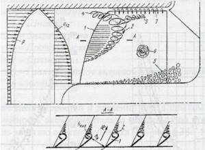
Particular attention in these works was paid to fuel pumps for aviation and space, where the issues of cavitation were very pressing. It has been found that the nature of cavitation depends on many factors, which are often difficult to establish. Several concepts of the origin and development of cavitation have been defined, for example, hydrodynamic, thermodynamic, nuclear. And each of them was somehow justified and expressed by appropriate criteria. By the end of the twentieth century, a general statement was formed that cavitation is a hydrodynamic phenomenon and depends both on the hydrodynamic properties of the hydraulic machine and the physical properties of the fluid. Cavitation begins when the pressure drops to a value equal to or less than the saturated vapor pressure (vapor elasticity), accompanied by a violation of the continuity of the flow and the formation of bubble-cavities filled with liquid vapor, gases released in it, or a mixture of them. When a cavity enters a zone of high pressure, the steam condenses into liquid droplets, and condensation occurs instantly. With such a rush of a mass of liquid with enormous acceleration into the closing voids and the formation of shocks, a local increase in pressure occurs at these points, reaching 300 kgf/cm2. In Fig. Figure 1 schematically shows the deformation of bubble-cavities and the direction of liquid movement during their collapse in various parts of the flow part - inside the flow and near the walls. These impacts are repeated tens of thousands of times per second. In a pump, the phenomenon of cavitation is accompanied by noise and increased low-frequency vibration, which results in premature failure of mechanical seals and bearings. There is also a decrease in pump operating parameters - flow, pressure, power and efficiency. During prolonged operation in cavitation mode, destruction of the surfaces of the impeller blades, the inlet pipeline, and sometimes the walls of the outlet is possible.
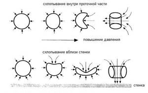
Rice. 1. The process of bubble collapse
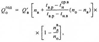
As a result of many experimental studies, explanations for many cavitation phenomena and processes have emerged, and some recommendations have been developed for practical calculations and operation of hydraulic machines. In particular, the assessment of the cavitation qualities of centrifugal pump impellers in the 30s of the twentieth century by prof. Rudnev S.S. (NPO "VNIIGidromash", Moscow) proposed a cavitation criterion called the cavitation speed coefficient Skr, which for practical calculations is reduced to the form:
where: n – rotation speed, rpm;
Qp = Qn + qunload – design flow of the impeller, m3/h;
Qn – pump flow;
qunload – leakage through the pump unloader;
Δhcr – critical (3% stall) cavitation reserve of the impeller according to GOST 6134, m;
The interpretation of the cavitation reserve in the current regulatory documents is different. For example, in accordance with clause 3.1.24 of GOST 6134, this is “... the total absolute suction pressure minus the pressure loss corresponding to the vapor pressure of the pumped liquid, referred to the reference plane NPSH.” In accordance with clause 3.28 of the international standard ISO 13709, this is “... the total absolute suction pressure, characterizing the excess of the suction pressure value over the saturated vapor pressure of the pumped liquid. Expressed in meters of liquid column.”
Note: the total absolute suction head (pressure) is taken without taking into account the process pressure in the receiving tank.
To ensure cavitation-free operation of the pump, the value of the permissible cavitation reserve Δhadd (required NPSHr according to ISO 13709) is taken within the range of (1.05-1.25)Δhcr. In addition, the cavitation reserve of the system Δhс (available NPSHа according to ISO 13709) should be Δhс ³ Δhcr + 0.5 m.
The range of pumping equipment for oil refining and petrochemical industries in the CIS countries consists mainly of centrifugal pumps: one- and two-stage cantilever pumps and multi-stage double-support pumps with outriggers. Among them there is a group of pumps that are used in installations for primary oil refining, as well as in installations for thermal and thermocatalytic processes for pumping out heavy residues from the bottom of the column. In all of the listed technological processes, the heavy residue in the column is boiling fuel oil or tar at a temperature of 360-380 °C. Moreover, the recommended residence time for fuel oil at the bottom of the atmospheric column is 5 minutes, for tar at the bottom of the vacuum column – 2–5 minutes. Based on these recommendations, the parameters of special, so-called “furnace” pumps are selected, which must select these residues and send them either to the furnace for further processing, or for coking in delayed coking units (DCU). “Oil” pumps, designed to load furnaces with diesel distillate, fuel oil or tar at temperatures up to 400° C and pressure up to 65 kgf/cm2, are considered the most problematic in oil refining. The problem of designing a hot high-pressure pump is to solve the following main problems:
· ensuring complete tightness of the shaft and connectors of housing parts;
· ensuring the necessary strength and rigidity of the used structural materials under conditions of high temperatures and pressures, as well as their corrosion and erosion resistance, because heavy residues are rich in sulfur compounds and finely dispersed impurities of an abrasive nature;
· ensuring thermal expansion of rotor and stator parts without misalignment and jamming of the rotor in the pump housing;
· ensuring high maintainability, because for dismantling, repair and subsequent installation of the pump in the installation, 2 to 4 days are allotted;
· ensuring the time between failures and 2–3-year overhaul interval required by regulatory documents.
Ensuring the last requirement is difficult to achieve, because pumps that remove heavy residues from the bottom of the column operate in pre-cavitation or already in cavitation modes. The reason for this is that these boiling residues are under their own vapor pressure, i.e., in a state of equilibrium with the vapor pressure. Thus, at the pump inlet there will be only geodetic pressure of the liquid in the column. Taking into account possible losses in the inlet pipeline and to eliminate possible gas formation in the pump under these conditions, it is recommended to keep the geodetic head value within 2.0 - 2.5 m. In other words, these values are the cavitation reserve of the system for the pump. In this case, the required values of the permissible cavitation reserve of the pump at flow rates of more than 300 m3/h are difficult to achieve with centrifugal pumps without special measures, and cavitation phenomena are always present to some extent.
Ways and methods for eliminating the harmful effects of cavitation in centrifugal pumps have been determined a long time ago. They can be distinguished as measures on the system in which the pump operates, and design decisions in the pump itself. The first include an increase in geodetic support in the column and a decrease in hydraulic losses in the inlet pipeline. Well-known design solutions in the pump are:
· reduction of rotation speed;
· reduction of the design flow due to the use of a double-entry impeller - double-flow;
· special design of the impeller and profiling of the blade;
· installation of an upstream wheel (auger) in front of the impeller;
· in multistage pumps - the use of a double-flow impeller of the first stage.
All of the above solutions have their advantages and disadvantages. For example, the use of screws significantly reduces the values of the critical cavitation speed coefficient. If for an impeller with a speed coefficient ns = 80 – 120 the coefficient Skr = 800 – 1000, then for a centrifugal screw wheel of the same speed this coefficient will be within Skr = 2000 – 2200, which reduces the value of Δhcr by almost 4 times. But the auger, by its hydrodynamic nature, is an axial impeller, which is designed for a very narrow feed range, and therefore normal operation of a pump with a centrifugal screw stage is not ensured throughout the entire operating feed range. The use of auger centrifugal stages is justified, for example, in energy pumps - condensate and large feed pumps, which operate at design modes for almost their entire service life. The use of screws allowed Sumy pump builders to create in the 60–80s a large group of feed and condensate pumps with improved cavitation characteristics. In total there are more than 50 standard sizes, including condensate (n = 1500 rpm) with a flow rate from 30 to 2200 m3/h, feed (n = 3000 rpm) with a flow rate of 580, 850 and 1650 m3/ h and power consumption up to 8000 kW, oil mains (n = 3000 rpm) with flow rates from 125 to 710 m3/h. Pumps of all listed sizes have been successfully operated for more than 30 years.
In oil refining, the pumps used are selected for the maximum possible design load of the installation (hypothetical) and therefore, in many cases, they operate for a long time in underload modes - partial flows. When the centrifugal screw stage operates at partial feeds, so-called reverse currents arise in the screw channels - countercurrents, which significantly change the flow pattern in the screw up to the formation of local zones with reduced pressure and, as a result, local cavitation in the screw channels.
Much attention was paid to the study of cavitation phenomena in the centrifugal screw stage in underload modes when creating special fuel pumps for aviation and space technology. Almost all studies were based on a physical experiment - visualization of the flow in a model pump under stroboscopic lighting under various operating modes. Processing photo and video recordings of the flow in the screw under various feed operating modes, measuring the velocity and pressure fields in front of the screw made it possible to present a physical picture of the flow in the screw and develop a mathematical model of this flow at partial feeds. The results of theoretical calculations performed using this model showed fairly good agreement with experimental data. Subsequently, the created mathematical model was widely used in the works of other authors to determine the geometric dimensions of the screw and its cavitation qualities.
Ultimately, the physical picture of the flow in the screw in underload modes, presented in Fig. 2 was theoretically substantiated, experimentally confirmed, and the following conclusions were drawn from it:
· when a centrifugal screw pump operates at feed rates Q ≤ 0.5Qopt, reverse currents (countercurrents) appear in the screw channels; they arise at the periphery of the entrance to the blade, push the main flow towards the axis and twist it;
· the flow in the screw is significantly non-axisymmetric, therefore, local zones with reduced pressure are formed at the boundaries between the direct flow and the reverse flow.
· the formation of a cavitation cavity occurs in local zones on the periphery of the inlet edges;
· the pumped liquid is heated;
· a vortex cord is formed in the inlet pipe, filled with gas and steam;
· self-oscillations occur.
Rice. 2. Flow structure in a screw when working with countercurrents
1 – profile cavity;
2 – stagnant zone (wake vortex);
3 – flow from a wake vortex along the main flow;
4 – counterflow;
5 – gas bubbles;
6 – cavitation vortex in variable speed screws.
Unlike classic axial impellers, countercurrent modes for augers are often operational, i.e. augers are almost always operated at different stages of cavitation and are accompanied by additional noise, flow pulsations, housing vibration and erosive wear. When the pressure at the pump inlet decreases, cavitation existing in the reverse current zone develops intensively; in the forward flow in the screw channels, the cavitation zone increases and is accompanied by a decrease in the intensity of reverse currents until they completely disappear; after this there is a complete breakdown. The most dangerous consequence of cavitation in a screw can be the occurrence of flow pulsations and self-oscillations, which “rock” the entire system and this process becomes uncontrollable.
LLC "SMZ" in its development of designs for a new generation of oil pumps - cantilever and two-support - uses centrifugal screw stages, but with a limitation of the operating flow range within the limits recommended by API 610, namely: 0.7Qopt ≤ Qр ≤ 1.1Qopt.
Reducing the rotation speed is a very effective way to reduce the effects of cavitation, but this method is not always justified, since to achieve a given head it is necessary to increase both the number of stages and the outer diameter of the impellers. This solution leads to a significant deterioration in the weight and size characteristics of the pump, and therefore requires optimization of options in each specific case.
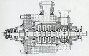
A more optimal solution in high-pressure multistage pumps is to use a double-flow impeller as the first stage. The domestic representative of this design is the single-barrel oil pump NT 560/335-300 produced by Volgogradneftemash OJSC (Fig. 3).
Rice. 3. Pump NT 560/335-300
And the most optimal solution for such a case is a combination of the two preceding ones - reducing the rotation speed and using a two-flow first stage. This solution is implemented, for example, in double-casing multistage pumps ADSL 8”x4 from Germany (Fig. 4) and “Kirloskar 250/200” from India (Fig. 5).
Rice. 4. ADSL pump 8”x4
Rice. 5. Pump “Kirloskar 250/200”
The indicated pumps at a rotation speed of 1500 rpm at a flow rate of 350 m3/h have values of the permissible cavitation reserve (Δhperm) at the level of 2.0 m, which is acceptable for the conditions of “furnace” pumps. The complication of the design is justified by ensuring reliable and durable cavitation-free operation. It should be noted that such a design of the flow part is quite common among leading pumping companies (Fig. 6 – 9).
Rice. 6. Large MBFP type feed pump
Rice. 7. Pump type WKTA Fig. 8. Condensate pump KsV 200-130
German
Rice. 9. Pump NDMg 360-350
In the 70s of the twentieth century, the KsV 200-130 condensate pump was created at JSC VNIIAEN (Sumy), which implemented the above-described solutions and additionally used upstream impellers (Fig. 9), which made it possible to obtain Δhadd values also at level 2.0 m.
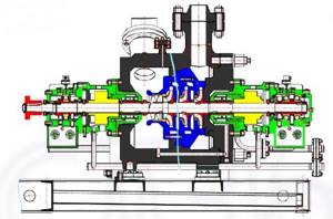
LLC "SMZ" for similar conditions proposed a double-casing, single-flow, 4-stage pump NDMg 360-350 with a pre-engaged impeller, type BB5 API 610 (Fig. 10), which at a rotation speed of 1500 rpm at a flow rate of about 350 m3/h has the value of the permissible cavitation reserve (Δhadd) at the level of 2.5 m.
Summarizing the above information for the operating conditions of high-pressure “furnace” pumps with flow rates of 300 – 600 m3/h, we can offer the following recommendations:
· the pump design must comply with types BB2 or BB5 according to ISO 13709;
· the design of a multistage pump of type BB5 with a double-flow impeller of the first stage is considered more preferable, despite the complexity of the pump design;
· when using a single-flow flow part with a screw-centrifugal first stage in the design of a pump, it is necessary to limit the long-term operating mode in terms of supply within the limits of (0.7 - 1.1) Qopt, where Qopt is the maximum efficiency mode.
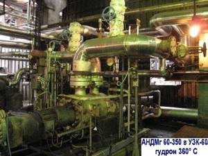
The above-mentioned NDMg 360-350 U2 pump and the ANDMg 360-350 U2 pump unit based on it, according to Technical Specifications TU U29.1-34933255-013:2007, belong to the new generation of oil pumps developed at SMZ LLC at the suggestion of the Association of Oil Refiners and Petrochemists (Moscow city). All pumping products of SMZ LLC comply with the requirements of current regulatory documents of Ukraine, Russia, the Republic of Belarus, international standards ISO 13709 and ISO 21049. Below is a table of supplied pumping units of type BB2 and BB5 to oil refining facilities of Ukraine, Russia and Belarus, and in Fig. . 11 – pumping unit ANDMg 60-350 in delayed coking unit No. 60 of the coke-bitumen production of LLC LUKOIL-Volgogradneftepererabotka.
List of pumping units
type ANDg, ANDMg according to TU U 29.1-34933255-013:2007
and ANMsg according to TU U 29.1-34933255-014:2007,
delivered to refineries and gas processing plants in the CIS countries from 2006 to 2021
| Standard size | Power Ned, kW | Col. | Standard size | Power Ned, kW | Col. | |
| ANDG 55-70 U2 | 22 | 2 | ANDMg 60-350 U2 | 160 | 6 | |
| ANDG 200-180 U2 | 132 | 4 | ANDMg 150-180 U2 | 75 | 1 | |
| ANDG 300-100 U2 | 90 | 2 | ANDMg 220-600 U2 | 500 | 2 | |
| ANDG 500-100 U2 | 160, 200 | 6 | ANDMg 360-350 U2 | 400 | 1 | |
| ANDG 500-160 U2 | 250 | 2 | ANDMg 600-320 U2 | 800 | 4 | |
| ANDG 1300-125 U2 | 250, 315, 500 | 10 | ANDMg 750-170 U2 | 630 | 2 | |
| ANDMg 25-125 U2 | 30 | 2 | ANMsg 450-500 U2 | 400 | 2 | |
| ANDMg 60-250 U2 | 75 | 1 | Total | 47 | ||
Rice. 10 .
Pumping unit ANDMg 60-350 U2 Share on social networks:
Design Features
Despite the simplicity of the device, there are features that must be taken into account during assembly:
- the incoming pipe is connected to the pump using a flange.
The pump for increasing the water pressure in the apartment will be responsible for supplying liquid with the required pressure; - the required speed and pressure are achieved through pipes of a certain diameter.
Water begins to quickly move to the center of the working container, where mixing of flows occurs; - speed control is carried out using special devices that are installed on both chamber pipes;
- The water moves through the safety valve to the outlet pipe, through which it returns to its starting point.
Constant movement creates heating of the water, the heat is converted into mechanical energy.
Heat calculations are made using the following formulas:
Epot = - 2*Ekin, where
Ekin = mV2/2 – unstable kinetic quantity.
Assembling a cavitation generator with your own hands will allow you to save not only on fuel, but also on the purchase of serial models.
The production of such heat generators has been established in Russia and abroad.
The devices have many advantages, but the main disadvantage - cost - reduces them to nothing. The average price for a household model is about 50-55 thousand rubles.
By independently assembling a cavitation heat generator, we obtain a device with high efficiency.
For correct operation of the device, it is necessary to protect the metal parts by painting. It is better to make parts that come into contact with liquid thick-walled, which will increase their service life.
In this video, watch a clear example of the operation of a homemade cavitation heat generator.
Subscribe to updates by E-Mail:
Fuel cavitator: reviews
We looked at the reviews on the Internet and decided to show them.
Stepan Georgievich, 38 years old
I have an extremely negative attitude towards all such things; I believe that the vast majority of such inventions are a scam. My son gave it to me, I still laughed, this is a birthday present. Then it was not worth as much as it is now, because it had just appeared. They installed it only a week later, and then I doubted it. It was winter, and the car started up not quite normally, somehow smoothly. I drove around, started watching the consumption and noticed a difference of almost 2 liters per hundred. To this day I don’t know if this is the case, but I don’t want to take it off.
Alexey, 28 years old
I have a GAZelle, I make money by intercity transportation. I often looked with envy at Transporters, Transits and Ducatos because they were diesel. After I installed the fuel cavitator, I don’t even think about changing the car, the 406 engine needs no more than 7 liters on the highway.
Pavel Alexandrovich, 34 years old
All my life I have been working as a driver of company cars, and now our fleet has been replenished with Logans. At first, I honestly admit, I couldn’t get used to the noise of the operation and the rather weak engine. Then the authorities ordered 4 fuel cavitators; my car was on the test list, so to speak. Well, what can I say, I’m happy that I was included in the list of testers, I have my own Nissan Tiida, I immediately ordered it, installed it, it became even better.
In conclusion, I would like to say the following. In such cases, all opponents shout that automakers would buy up this business and install it. In practice, this would mean that companies would admit their insolvency and inability to develop new technologies.
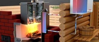
Heater structure and operating principle
Cavitation heating is characterized by the formation of bubbles from steam in the working fluid. As a result of this action, the pressure gradually decreases due to the high flow rate. It should be noted that the necessary vaporization is set by special radiation of laser pulses or acoustics set by certain sounds. Closed air regions mix with the water mass, after which they enter a high-pressure zone, where they open and emit the expected shock wave.
Cavitation-type equipment differs in the way it operates. Schematically it looks like this:
- The water flow moves through the cavitator, in which the working pressure entering the working tank is ensured using a circulation pump.
- Next, in such containers the speed and, accordingly, the pressure of the liquid increases through tubes installed according to the drawings.
- The flows, reaching the central part of the chamber, mix, resulting in cavitation.
- As a result of the described process, the steam bubbles do not increase in size, and there is no interaction between them and the electrodes.
- After this, the water moves to the opposite part of the container and returns to complete a new circle.
- Heating is provided by the movement and expansion of the liquid at the exit from the nozzle.
From the operation of the vortex installation it is clear that its design is uncomplicated and simple, but at the same time it provides quick and profitable heating of the room.
Working principle of induction heating
An induction heater uses the energy of an electromagnetic field, which the heated object absorbs and converts into heat. To generate a magnetic field, an inductor is used, i.e. a multi-turn cylindrical coil. Passing through this inductor, an alternating electric current creates an alternating magnetic field around the coil.
A homemade inventory heater allows you to heat quickly and to very high temperatures. With the help of such devices you can not only heat water, but even melt various metals
If a heated object is placed inside or near the inductor, it will be penetrated by the flux of the magnetic induction vector, which constantly changes over time. In this case, an electric field arises, the lines of which are perpendicular to the direction of the magnetic flux and move in a closed circle. Thanks to these vortex flows, electrical energy is transformed into thermal energy and the object heats up.
Thus, the electrical energy of the inductor is transferred to the object without the use of contacts, as happens in resistance furnaces. As a result, thermal energy is spent more efficiently, and the heating rate increases noticeably. This principle is widely used in the field of metal processing: melting, forging, soldering, surfacing, etc. With no less success, a vortex induction heater can be used to heat water.
Types of heaters
A cavitation heating boiler is one of the most common types of heaters. The most popular of them:
- Rotary installations, among which the Griggs device deserves special attention. The essence of its action is based on a rotary centrifugal pump. Externally, the described design resembles a disk with several holes. Each such niche is called a Griggs cell; their number and functional parameters are interdependent with the drive speed and the type of generating set used. The working fluid is heated in the space between the rotor and stator due to its rapid movement along the disk surface.
- Static heaters. The boilers do not have any moving parts; cavitation in them is ensured by special Laval elements. A pump installed in the heating system sets the required water pressure, which begins to move quickly and heat up. Due to the narrow holes in the nozzles, the liquid moves at an accelerated rate. Due to its rapid expansion, the cavitation necessary for heating is achieved.
The choice of a particular heater depends on the needs of the person. It should be taken into account that the rotary cavitator is more productive, and it is also smaller in size.
The peculiarity of the static unit is the absence of rotating parts, which determines its long service life. Duration of operation without maintenance reaches 5 years. If the nozzle breaks, it can be easily replaced, which costs much less than purchasing a new working element for a rotary installation.
Advantages and disadvantages
Compared to other heat generators, cavitation units have a number of advantages and disadvantages.
The advantages of such devices include:
- A much more efficient mechanism for generating thermal energy;
- Consumes significantly less resources than fuel generators;
- Can be used for heating both low-power and large consumers;
- Completely environmentally friendly - does not emit harmful substances into the environment during operation.
The disadvantages of cavitation heat generators include:
- Relatively large dimensions - electric and fuel models have much smaller dimensions, which is important when installed in an already used room;
- Great noise due to the operation of the water pump and the cavitation element itself, which makes it difficult to install in domestic premises;
- Ineffective ratio of power and performance for rooms with small square footage (up to 60 m2 it is more profitable to use a gas, liquid fuel or equivalent electrical power with a heating element).\
Self-production of equipment
It is quite possible to create a cavitator with your own hands, but first you should familiarize yourself with the schematic features, exact drawings of the unit, understand and study in detail the principle by which it operates. The simplest model is considered to be the Potapov VTG with an efficiency index of 93%. Schematically, the heat generator is quite simple and would be suitable for everyday and industrial use.
When starting to assemble the unit, it is necessary to select a pump for the system, which must fully meet the power requirements and the required thermal energy. For the most part, the described generators are shaped like a nozzle; such models are the most convenient and simplest for home use.
Creating a cavitator is impossible without the preliminary preparation of certain tools and devices. These include:
- inlet and outlet pipes equipped with taps;
- pressure gauges;
- a thermometer, without which it is impossible to measure temperature;
- sleeves that complement thermometers;
- valves, with the help of which air pockets are eliminated from the entire heating system.
Experts recommend monitoring the diametrical cross-section of the hole that is present between the confuser and the diffuser. Optimal limits range from 8 to 15 units; going beyond these limits is undesirable.
The sequence of constructing a cavitation heat generator with your own hands is represented by the following steps:
- Selecting a pump that is designed for operation with high-temperature liquids. Otherwise, it will quickly fail. There is a mandatory requirement for such an element: creating a pressure of 4 atmospheres.
- Making a container for cavitation. The main condition is the selection of the required cross-section of the passage channel.
- Selection of nozzle taking into account configuration features. Such a part can be cylindrical, cone-shaped, or round. It is important that a vortex process develops at the water inlet into the container.
- Preparing the external contour is an important procedure. It is a curved tube that extends from the cavitation chamber. Next, it is connected to two thermometer sleeves and two pressure gauges, as well as to an air valve placed in the space between the outlet and the inlet.
When the work with the body is finished, you should experiment with the heater. The procedure consists of connecting the pumping unit to the electrical network, while the radiators are connected to the heating system. The next step is to turn on the network.
Pressure gauge readings must be strictly monitored. The difference between the numbers at the inlet and outlet should range between 8-12 atmospheres.
If the structure is working properly, the required amount of water is supplied to it. A good indicator is heating the liquid by 3-5 degrees in 10-15 minutes.
A cavitation type heater is a cost-effective installation; it heats a building in a short time, and is also extremely economical. If desired, it can be easily constructed at home, for which you will need accessible and inexpensive devices.
Purpose of cavitators
The fuel cavitator is used as an additional part in the fuel injection system to clean it of various impurities and bring it into a state in which it is better accepted by the engine. The emission of harmful substances into the atmosphere is also reduced, and this allows you to significantly save money on various cleaning devices.
Initially, cavitation units were used only in the oil refining and chemical industries to reduce the amount of production waste and improve product quality. Later they created a mini version for cars - it had not yet had time to firmly enter into use and become widespread.
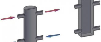
Rotary vortex heat generator
Scheme of a vortex heat generator.
This hydrodynamic design is a slightly modified centrifugal pump. In other words, there is a pump housing (in this case it is a stator) with outlet and inlet pipes and a working chamber. Inside the housing there is a rotor that acts as an impeller. The main difference from a conventional pump is the rotor. There are a large number of structural rotor versions of vortex heat generators known; it makes no sense to describe them all. The simplest of them is a disk. A considerable number of blind holes of a certain diameter and depth are drilled on its cylindrical surface. These holes are called Griggs cells (the American inventor who first tested this design). The dimensions and number of these cells must be determined based on the size of the rotor disk and the rotation speed of the electric motor that drives it into rotation.
The stator (heat generator housing) in most cases is made in the form of a hollow cylinder, that is, a pipe that is plugged with flanges on both sides. The gap between the inner wall of the stator and the rotor is very small and amounts to approximately 1-1.5 mm.
Water will heat up in the gap between the stator and the rotor. It is facilitated by fluid friction on the surface of the rotor and stator, when the former rotates quickly. Cavitation processes and turbulence of water in rotor cells are also of great importance for heating water. The rotor rotation speed in most cases is 3000 rpm if its diameter is 300 mm. As the rotor diameter decreases, the rotation speed should increase.
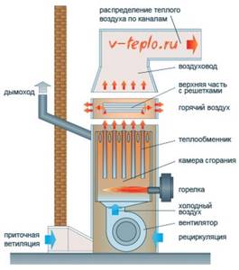
Scheme of the operating principle of an air heating heat generator.
Despite its simplicity, this design requires great manufacturing precision. In addition, the rotor will need to be balanced. It will also be necessary to resolve the issue of sealing the rotor shaft. You should be aware that sealing elements need to be replaced regularly.
From what was said above, it follows that the resource of these installations is not very long. It is worth noting that the operation of rotary heat generators creates increased noise. Compared to static-type structures, they have 20-30% greater productivity. Rotary devices can even produce steam.
Creating a wireframe and selecting elements
To make a homemade vortex heat generator, to connect it to the heating system, you will need an engine.
And the greater its power, the more it will be able to heat the coolant (that is, it will produce more heat faster and more). However, here it is necessary to focus on the operating and maximum voltage in the network that will be supplied to it after installation.
When choosing a water pump, you need to consider only those options that the engine can spin. At the same time, it must be of a centrifugal type, otherwise there are no restrictions on its choice.
You also need to prepare a frame for the engine. Most often it is a regular iron frame into which iron corners are attached. The dimensions of such a frame will depend, first of all, on the dimensions of the engine itself.
After selecting it, it is necessary to cut the corners of the appropriate length and weld the structure itself, which should allow placing all the elements of the future heat generator.
Next, to mount the electric motor, you need to cut out another corner and weld it to the frame, but this time across. The final touch in preparing the frame is painting, after which you can already attach the power plant and pump.
Static cavitation heat generator
This type of heat generator is only conventionally called static. This is due to the absence of rotating parts in the cavitator vortex structure. In order to create cavitation processes, various types of nozzles are used.
For cavitation to occur, it is necessary to ensure a high speed of movement of the liquid in the cavitator. To do this, use an ordinary centrifugal pump. The pump will pressurize the fluid in front of the nozzle. It will rush into the nozzle opening, which has a much smaller cross-section than the supply pipeline. This provides greater speed at the exit of the nozzle. With the help of a sharp expansion of the liquid, cavitation occurs. This will be facilitated by the friction of the liquid on the surface of the channel and the turbulence of the water that occurs in the event of a sharp alignment of the jet from the nozzle. The water is heated for the same reasons as in a rotary vortex design, but with slightly less efficiency.
Scheme of the operating principle of a stationary heat generator.
The design of a static heat generator does not require high precision manufacturing of parts. When manufacturing these parts, machining is reduced to a minimum compared to the rotor design. Due to the absence of rotating parts, the issue of sealing parts and mating assemblies can be easily resolved. Balancing is not needed here either. The service life of the cavitator is much longer. Even if the nozzle wears out its life, manufacturing and replacing it will require much lower material costs. In this case, the rotary cavitation heat generator will need to be manufactured anew.
The disadvantage of a static device is the cost of the pump. However, the cost of constructing a heat generator for this device is practically no different from a rotor vortex design. If we remember the service life of both installations, this disadvantage will turn into an advantage, because if the cavitator is replaced, there is no need to change the pump.
Therefore, it makes sense to think about making a static vortex heat generator.
Advantages and disadvantages
Like any other device, a cavitation-type heat generator has its positive and negative sides . Among the advantages are the following indicators:
The weaknesses of the Potapov generator are considered:
The generator used in industry differs from the home version only in dimensions. However, sometimes the power of a home unit is so high that there is no point in installing it in a one-room apartment, otherwise the minimum temperature when the cavitator is operating will be at least 35°C.
The video shows an interesting version of a solid fuel vortex heat generator
Making a heat generator with your own hands
Selecting a pump for the device
Do-it-yourself boiler diagram for testing.
You should start by choosing a pump for the device being manufactured. To do this, you will need to determine its operating parameters. It does not matter whether it is a circulation pump or a pressure booster. What matters is the pump performance, operating pressure, and maximum temperature of the pumped liquid.
Not all designs can be used for pumping high-temperature liquids. If you do not pay attention to this parameter when choosing a pump, its service life may be significantly shorter than that declared by the manufacturer.
The efficiency of the heat generator depends on the amount of pressure that the pump can develop. The greater the pressure, the greater the pressure drop will be. Consequently, the heating of the liquid pumped through the cavitator will be more efficient. However, you should not at all chase the maximum figures in the characteristics of the pumps.
Pump performance has virtually no effect on the efficiency of water heating.
The power of the heat generator pump determines the conversion coefficient of electrical energy into thermal energy.
Application
In industry and in everyday life, cavitation heat generators have found implementation in a wide variety of fields of activity. Depending on the tasks assigned, they are used for:
- Heating – inside the installations, mechanical energy is converted into thermal energy, due to which the heated liquid moves through the heating system. It should be noted that cavitation heat generators can heat not only industrial facilities, but also entire villages.
- Heating running water - a cavitation unit is capable of quickly heating liquid, due to which it can easily replace a gas or electric water heater.
- Mixing of liquid substances - due to rarefaction in the layers to obtain small cavities, such units make it possible to achieve the proper quality of mixing of liquids that do not naturally combine due to different densities.
Manufacturing and development of cavitator
Diagram of a stationary heat generator.
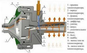
There are a large number of designs of static cavitators, but in almost all cases they are made in the form of a nozzle. The nozzle is most often taken as a basis and modified by the designer. The classic design is shown in the picture (IMAGE 1).
The first thing you need to pay attention to is the cross-section of the channel between the confuser and the diffuser. You should not narrow its cross-section too much, thereby trying to ensure maximum pressure drop. The volume of water that is pumped through the nozzle will be too small. When mixed with cold water, it will not transfer enough heat to it. This means that the total volume of water will not be able to heat up quickly. In addition, the small cross-section of the channel will contribute to the airing of the water that enters the inlet pipe of the working pump. As a result, this pump will operate noisily, and cavitation may occur in the device itself.
The best performance can be achieved with a channel opening diameter of 10-15 mm.
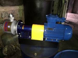
Pump installation
Now you will need to select a water pump. Now in specialized stores you can purchase a unit of any modification and power.
What should you pay attention to?
- The pump must be centrifugal.
- Your engine will be able to spin it.
Install a pump on the frame; if you need to make more cross members, make them either from a corner or from strip iron of the same thickness as the corner. It is hardly possible to make a coupling without a lathe. Therefore, you will have to order it somewhere.
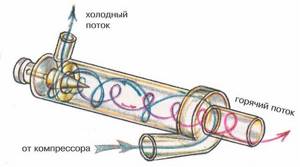
Diagram of a hydraulic vortex heat generator.
Potapov's vortex heat generator consists of a housing made in the form of a closed cylinder. At its ends there must be through holes and pipes for connection to the heating system. The secret of the design is inside the cylinder. There should be a nozzle behind the inlet hole. Its hole is selected individually for a given device, but it is desirable that it be half the size of a quarter of the diameter of the pipe body. If you do less, the pump will not be able to pass water through this hole and will begin to heat up. In addition, internal parts will begin to rapidly deteriorate due to the phenomenon of cavitation.
Tools: angle grinder or hacksaw, welding machine, electric drill, adjustable wrench.
Materials: thick metal pipe, electrodes, drills, 2 threaded pipes, couplings.
- Cut a piece of thick pipe with a diameter of 100 mm and a length of 500-600 mm. Make an external groove on it approximately 20-25 mm and half the thickness of the pipe. Cut the thread.
- Make two rings 50 mm long from the same pipe diameter. Cut an internal thread on one side of each half ring.
- Make covers from the same thickness of flat metal as the pipe and weld them on the unthreaded side of the rings.
- Make a central hole in the covers: one with the diameter of the nozzle, and the other with the diameter of the pipe. Make a chamfer on the inside of the cover, where the jet is located, with a larger diameter drill. The result should be a nozzle.
- Connect the heat generator to the system. Connect the pipe where the nozzle is located to the pump into the hole from which water is supplied under pressure. Connect the heating system input to the second pipe. Connect the outlet from the system to the pump inlet.
Water under the pressure created by the pump will pass through the nozzle of the vortex heat generator, which you make yourself. In the chamber it will begin to heat up due to intense stirring. Then feed it into the heating system. To regulate the temperature, install a ball locking device behind the nozzle. Cover it, and the vortex heat generator will circulate water inside the housing longer, which means the temperature in it will begin to rise. This is roughly how this heater works.
Manufacturing of a hydrodynamic circuit
To manufacture a hydrodynamic circuit, it is first necessary to draw a diagram of the circuit. (IMAGE 2) In the diagram you can see:
- pressure gauge at the nozzle outlet (measurement of outlet pressure);
- thermometer (measurement of temperature at the system entrance);
- air bleed valve (removing air from the system);
- outlet pipe with tap;
- thermometer sleeve;
- inlet pipe with tap;
- thermometer sleeve at the inlet;
- pressure gauge at the nozzle inlet (measurement of pressure at the system inlet).
Waste oil heater circuit diagram.
The circuit device is a pipeline, the inlet of which is connected to the outlet pipe of the pump, and the outlet to the inlet. You need to weld a nozzle into the pipeline, pipes for connecting a pressure gauge, sleeves for installing a thermometer, a fitting for the valve to bleed air, and a fitting for connecting the heating circuit.
In this diagram, the water will move counterclockwise. Water is supplied to the circuit through the lower pipe, and water is discharged from it through the upper. The pressure drop will be regulated by a valve located between the outlet and inlet pipes.
A little history
The vortex thermal generator is considered a promising and innovative development. Meanwhile, the technology is not new, since almost 100 years ago scientists were thinking about how to apply the phenomenon of cavitation.
Ranque tube, penetrating into which the gaseous medium is divided into hot and cold air - this phenomenon was discovered at the beginning of the twentieth century, and is used in practice today
The first operational pilot plant, the so-called “vortex tube”, was manufactured and patented by the French engineer Joseph Rank in 1934.
Rank was the first to notice that the temperature of the air at the inlet to the cyclone (air purifier) differs from the temperature of the same air stream at the outlet. However, at the initial stages of bench tests, the vortex tube was tested not for heating efficiency, but, on the contrary, for the cooling efficiency of the air stream.
The principle of operation of the vortex tube shown in the diagram is simple - the flow passes through the swirl chamber, where it is divided into two streams with different temperatures
The technology received new development in the 60s of the twentieth century, when Soviet scientists figured out how to improve the Ranque tube by running liquid into it instead of an air jet.
Due to the higher density of the liquid medium, compared to air, the temperature of the liquid, when passing through the vortex tube, changed more intensively. As a result, it was experimentally established that the liquid medium, passing through the improved Ranque tube, heated up abnormally quickly with an energy conversion coefficient of 100%!
Unfortunately, there was no need for cheap sources of thermal energy at that time, and the technology did not find practical application. The first operating cavitation installations designed to heat a liquid medium appeared only in the mid-90s of the twentieth century.
The photo shows a demonstration vortex generator in which water circulates in a closed loop
A series of energy crises and, as a consequence, increasing interest in alternative energy sources served as the reason for resuming work on effective converters of the energy of water jet movement into heat. As a result, today you can buy a unit with the required power and use it in most heating systems.
Price overview
A cavitation heat generator should be considered an anomalous device, since it is an almost ideal device. Buying one is quite a difficult task, since the prices for such heaters are inflated .
In different cities of our country, prices for these devices vary. The price for a device with a power of up to 50 kW in Volgograd is 50,000 rubles. In Izhevsk its cost is the same as in Volgograd. In St. Petersburg, you will have to pay 55,000 rubles to purchase such a device. In Kyiv, the price tag for it is set at 50,000 rubles.
Vortex-type cavitation generators have a simpler design. However, they are inferior in terms of efficiency. If we talk about the most popular device models on the market, we will highlight the Radex rotary pump-heat generator . Another popular device is the Tornado electric shock generator. Along with it, there is good demand for the electrohydraulic shock Vektorplus. In private homes you can use mini-devices TSGC2-3k (3 kVA) and Belarusian Yurle-K.
If you decide to purchase a cavitation generator, then it is better to contact specialized companies or partner stores located in Russia, Belarus and other CIS countries.