Thermal loads of the object
Thermal loads are calculated in the following sequence.
- 1. Total volume of buildings according to external measurements: V=40000 m3.
- 2. The estimated internal temperature of heated buildings is: ttemp = +18 C - for administrative buildings.
- 3. Estimated heat consumption for heating buildings:
4. Heat consumption for heating at any outside temperature is determined by the formula:
where: tvr — internal air temperature, C; tn — outside air temperature, C; tн0 is the coldest outside air temperature during the heating period, C.
- 5. At outside air temperature tн = 0С, we obtain:
- 6. At outside air temperature tн= tнв = -2С, we get:
- 7. At the average outside air temperature during the heating period (at tн = tнср.о = +3.2С) we obtain:
- 8. At outside air temperature tн = +8С we obtain:
- 9. At outside air temperature tн = -17С, we obtain:
10. Estimated heat consumption for ventilation:
,
where: qв - specific heat consumption for ventilation, W/(m3·K), we take qв = 0.21- for administrative buildings.
11. At any outside air temperature, heat consumption for ventilation is determined by the formula:
- 12. At the average outside air temperature during the heating period (at tн = tнср.о = +3.2С) we obtain:
- 13. At outside air temperature = = 0C, we get:
- 14. At outside air temperature = = +8C, we get:
- 15. At outside air temperature ==-14C, we get:
- 16. At outside air temperature tн = -17С, we obtain:
17. Average hourly heat consumption for hot water supply, kW:
where: m - number of personnel, people; q — hot water consumption per person per day, l/day (q = 120 l/day); c is the heat capacity of water, kJ/kg (c = 4.19 kJ/kg); tg - temperature of hot water supply, C (tg = 60C); ti is the temperature of cold tap water in the winter txz and summer txl periods, C (txz = 5C, txl = 15C);
— the average hourly heat consumption for hot water supply in winter will be:
— average hourly heat consumption for hot water supply in summer:
- 18. Let us summarize the results obtained in Table 2.2.
- 19. Based on the data obtained, we construct a total hourly graph of heat consumption for heating, ventilation and hot water supply of the facility:
; ; ; ;
20. Based on the resulting total hourly graph of heat consumption, we construct an annual graph for the duration of the heat load.
Table 2.2 Dependence of heat consumption on outside air temperature
| Heat consumption | tnm= -17С | tno= -14C | tнв=-2С | tn= 0С | tav.o=+3.2С | tnk= +8С |
| , MW | 0,91 | 0,832 | 0,52 | 0,468 | 0,385 | 0,26 |
| , MW | 0,294 | 0,269 | 0,168 | 0,151 | 0,124 | 0,084 |
| , MW | 0,21 | 0,21 | 0,21 | 0,21 | 0,21 | 0,21 |
| , MW | 1,414 | 1,311 | 0,898 | 0,829 | 0,719 | 0,554 |
| 1,094 | 1,000 | 0,625 | 0,563 | 0,463 | 0,313 |
Annual heat consumption
To determine heat consumption and its distribution by season (winter, summer), equipment operating modes and repair schedules, it is necessary to know the annual fuel consumption.
1. The annual heat consumption for heating and ventilation is calculated using the formula:
,
where: - average total heat consumption for heating during the heating period; — average total heat consumption for ventilation during the heating period, MW; — duration of the heating period.
2. Annual heat consumption for hot water supply:
where: - average total heat consumption for hot water supply, W; — duration of operation of the hot water supply system and duration of the heating period, hours (usually hours); — coefficient of reduction in hourly consumption of hot water for hot water supply in the summer; - respectively, the temperature of hot water and cold tap water in winter and summer, C.
3. Annual heat consumption for thermal loads of heating, ventilation, hot water supply and technological load of enterprises according to the formula:
,
where: — annual heat consumption for heating, MW; — annual heat consumption for ventilation, MW; — annual heat consumption for hot water supply, MW; — annual heat consumption for technological needs, MW.
MWh/year.
Determination of hourly and annual consumption of thermal energy for heating
The maximum hourly consumption of thermal energy for heating a building (building) is based on aggregated indicators and is determined according to the formula Qр from = q from x V (tв – tрн) x 10-6, Gcal/h where: q from – specific thermal characteristic of the building, kcal (m3°C); V – external volume of the building, m3; tв – air temperature inside heated buildings, °C; trn – outside air temperature for calculating heating systems, °C The annual consumption of thermal energy for heating is determined by the formula: Qyear from = Zot x Qref x (( Tv – Tso)/( Tv – Tn)) x Po, Gcal/year where: Qref – maximum hourly heat consumption for heating, Gcal/h; Rho – duration of the heating period, days; Zot – operating time per day, h; Тсо – average temperature of outside air during the heating period, °С Тн – design temperature of outside air for designing heating and ventilation, °С Тв – design temperature of internal air of heated buildings, °С CLIMATOLOGICAL DATA ACCORDING TO NSB 2.04.02 – 2000 (Minsk region. ) Heating period Ro = 198 Average outdoor air temperature for the heating period Tso = -0.9 ° C Design indoor air temperature Tv = 15 - 21 ° C Design air temperature for designing heating and ventilation Tr = -24 ° C Cold water temperature summer Тхл =10°С Cold water temperature winter Тхз =5°С. EXAMPLE Operating mode of a production plant system 9248 m3 Coefficient of reduction in hot water consumption in summer S =1 Number of hours of operation per day of the heating system Zo= 24 The same, ventilation systems Zw= 12 The same, hot water supply systems Zgv =12 Number of days of operation per year of the system hot water supply Ргв =198 Production building V = 9248 m3; tв = 16°С; q from = 0.35 kcal/(m3h°C); Qhour from. = 0.35 x 9248 x (16-(-24)) = 129570 kcal/h = 0.130 Gcal/h Qyear from = 24 x 0.130 x(16-(-0.9)/(16-(-24) x198 = 261 Gcal/year Determination of hourly and annual thermal energy consumption for ventilation
What is needed for calculation
The so-called thermal calculation is carried out in several stages:
- First, it is necessary to determine the heat losses of the building itself. Typically, heat loss is calculated for rooms that have at least one external wall. This indicator will help determine the power of the heating boiler and radiators.
- Then the temperature regime is determined. Here it is necessary to take into account the relationship of three positions, or rather, three temperatures - the boiler, radiators and indoor air. The optimal option in the same sequence is 75C-65C-20C. It is the basis of the European standard EN 442.
- Taking into account the heat loss of the room, the power of the heating batteries is determined.
- The next stage is hydraulic calculation. It is this that will allow you to accurately determine all the metric characteristics of the elements of the heating system - the diameter of pipes, fittings, shut-off valves, etc. Plus, based on the calculation, the expansion tank and circulation pump will be selected.
- The power of the heating boiler is calculated.
- And the last stage is determining the total volume of the heating system. That is, how much coolant will be needed to fill it. By the way, the volume of the expansion tank will also be determined based on this indicator. Let us add that the heating volume will help you find out whether the volume (number of liters) of the expansion tank, which is built into the heating boiler, is enough, or whether you will have to purchase additional capacity.
By the way, regarding heat losses. There are certain norms that are set by experts as a standard. This indicator, or more precisely, the ratio, determines the future efficient operation of the entire heating system as a whole. This ratio is 50/150 W/m². That is, the ratio of the system power and the heated area of the room is used here.
Calculation formula
Thermal energy consumption standards
Thermal loads are calculated taking into account the power of the heating unit and the heat losses of the building. Therefore, in order to determine the power of the designed boiler, it is necessary to multiply the heat loss of the building by an increasing factor of 1.2. This is a kind of reserve equal to 20%.
Why is such a coefficient necessary? With it you can:
- Predict the drop in gas pressure in the pipeline. After all, in winter there are more consumers, and everyone tries to take more fuel than others.
- Vary the temperature inside the house.
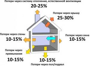
Let us add that heat losses cannot be distributed evenly throughout the entire building structure. The difference in indicators can be quite large. Here are some examples:
- Up to 40% of the heat leaves the building through the external walls.
- Through floors - up to 10%.
- The same applies to the roof.
- Through the ventilation system - up to 20%.
- Through doors and windows - 10%.
So, we sorted out the design of the building and made one very important conclusion: the heat losses that need to be compensated depend on the architecture of the house itself and its location. But much is also determined by the materials of the walls, roof and floor, as well as the presence or absence of thermal insulation
This is an important factor.
For example, let’s determine the coefficients that reduce heat loss, depending on window structures:
- Ordinary wooden windows with ordinary glass. To calculate thermal energy in this case, a coefficient of 1.27 is used. That is, through this type of glazing there is a leakage of thermal energy equal to 27% of the total.
- If plastic windows with double-glazed windows are installed, then a coefficient of 1.0 is used.
- If plastic windows are installed from a six-chamber profile and with a three-chamber double-glazed window, then a coefficient of 0.85 is taken.
Let's move on, dealing with the windows. There is a certain relationship between the area of the room and the area of window glazing. The larger the second position, the higher the heat loss of the building. And there is a certain relationship here:
- If the window area in relation to the floor area has only a 10% indicator, then a coefficient of 0.8 is used to calculate the thermal power of the heating system.
- If the ratio is in the range of 10-19%, then a coefficient of 0.9 is applied.
- At 20% - 1.0.
- At 30% -2.
- At 40% - 1.4.
- At 50% - 1.5.
And these are just the windows. And there is also the influence of the materials used in the construction of the house on thermal loads. Let's arrange them in the table, where wall materials will be located with a decrease in heat losses, which means their coefficient will also decrease:
Type of building material
As you can see, the difference from the materials used is significant. Therefore, even at the stage of designing a house, it is necessary to determine exactly what material it will be built from. Of course, many developers build a house based on the budget allocated for construction. But with such layouts it is worth reconsidering it. Experts assure that it is better to invest initially in order to later reap the benefits of savings from operating the house. Moreover, the heating system in winter is one of the main expense items.
Sizes of rooms and number of floors of the building
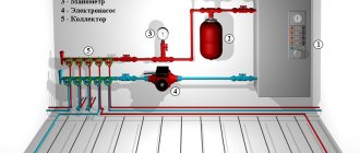
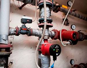
Heating system diagram
So, we continue to understand the coefficients that affect the heat calculation formula. How do room sizes affect thermal loads?
- If the ceiling height in your house does not exceed 2.5 meters, then the calculation takes into account a coefficient of 1.0.
- At a height of 3 m, 1.05 is already taken. It's a minor difference, but it has a significant impact on heat loss if the total area of the house is large enough.
- At 3.5 m - 1.1.
- At 4.5 m -2.
But such an indicator as the number of storeys of a building affects the heat loss of a room in different ways. Here it is necessary to take into account not only the number of floors, but also the location of the room, that is, on which floor it is located. For example, if this is a room on the first floor, and the house itself has three or four floors, then a coefficient of 0.82 is used for the calculation.
When moving a room to the upper floors, the rate of heat loss also increases. In addition, you will have to take into account the attic - whether it is insulated or not.
As you can see, in order to accurately calculate the heat loss of a building, it is necessary to determine various factors. And they all must be taken into account. By the way, we have not considered all factors that reduce or increase heat losses. But the calculation formula itself will mainly depend on the area of the heated house and on an indicator called the specific value of heat loss. By the way, in this formula it is standard and equal to 100 W/m². All other components of the formula are coefficients.
ANNUAL HEAT CONSUMPTION
To determine fuel consumption, develop equipment use modes, repair schedules, etc. it is necessary to know the annual heat consumption for heat supply, as well as its distribution by season (winter, summer) or by individual months. The annual heat consumption by consumers in the region is determined by the formula
,
where Qyear, Qyear, Qyear, Qthyear are the annual heat consumption for heating, ventilation, hot water supply, and technological needs.
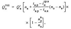
Annual heat consumption for heating
where Qav
— average heat consumption during the heating period, J/s or kcal/h;
nо - duration of operation of the heating system, s/year or h/year; for residential and public buildings n0
is the duration of the heating period; nd — duration of operation of standby heating, s/year or h/year; tin.d — internal air temperature during standby heating operation, °C.
Average heat consumption for the heating period
For residential and public buildings Qо/= Q/, where Q' is the estimated heat loss of the building at outside temperature tno
.
For industrial buildings Q'о = Q'—Qт
in, where
Qtv
is internal heat generation;
tнср.о - the average temperature of the heating period for residential and public buildings, for industrial buildings tнср.о - the average temperature of the outside air during the heating period.
The annual heat consumption for ventilation is determined by the formula
where Qv/ is the estimated heat consumption for ventilation, J/s or kcal/h; pv
— duration of the heating period with outside air temperature
tн <
tнв, s/year or h/year (with tнв = tнв
=
0);
ndv - duration of the heating period when ventilation does not work, s/year or h/year; tнср.в - average outside air temperature for the period from the beginning of the heating period tH=
tн.к to tн=tн.в.
Annual heat consumption for hot water supply
where Qгср.н
— average weekly heat consumption for hot water supply, J/s or kcal/h;
pg n0
- duration of operation of the hot water supply system and duration of the heating period, s/year/hour/year; b—coefficient taking into account the change in the average weekly water consumption for hot water supply during the non-heating period in relation to the heating period; in the absence of more accurate data, it is recommended to accept: b = 0.8 for the housing and communal services sector of all areas, except for resort and southern cities; b = 1.5 for the housing and communal services sector of resort and southern cities; b= 1 for industrial enterprises.
The annual heat consumption for technological needs is determined on the basis of the annual heat consumption schedule. An approximate graph of heat consumption by month is shown in Fig. 3.
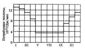
Rice. 3. Approximate graph of heat consumption by month of the year
Heat load duration chart
To establish an economical mode of operation of heating equipment and select the most optimal parameters of the coolant, it is necessary to know the duration of operation of the heat supply system under various modes throughout the year. For this purpose, graphs of the duration of the thermal load are constructed (Rossander graphs).
The method for plotting the duration of seasonal heat load is shown in Fig. 4. Construction is carried out in four quadrants. In the upper left quadrant, graphs are plotted depending on the outside temperature tH,
heating load
Q0,
ventilation
QB
and total seasonal load
(Q0 +
<2).
The lower left quadrant shows the curve of the duration of standing n
during the heating period of external temperatures tn equal to a given temperature or lower.
In the lower right quadrant, a straight line is drawn at an angle of 45° to the vertical and horizontal axes, used to transfer scale values .
from the lower left quadrant to the upper right quadrant.
The graph of the duration of the thermal load 5 is constructed for different external temperatures tн
at the points of intersection of the dashed lines that determine the thermal load and the duration of standing loads equal to or greater than this.

Area under the curve 5
The duration of the heat load is equal to the heat consumption for heating and ventilation during the heating season Qyear.
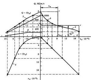
Rice. 4. Plotting the duration of seasonal heat load
In the case when the heating or ventilation load changes by hour of the day or day of the week, for example, when during non-working hours industrial enterprises are switched to standby heating or the ventilation of industrial enterprises does not operate around the clock, three heat consumption curves are plotted on the graph: one (usually a solid line) based on the average heat consumption per week for heating and ventilation at a given outside temperature; two (usually a dotted line) based on the maximum and minimum heating and ventilation loads at the same outside temperature tH.
This construction is shown in Fig. 5.
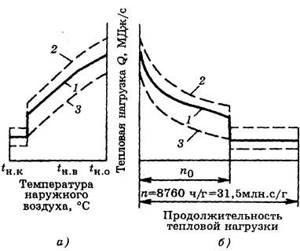
Rice. 5. Integral graph of the total load of the area
A
—
Q
= f(tн);
b
- graph of the duration of the thermal load;
1 — weekly average hourly load; 2
— maximum hourly total load;
3
- minimum hourly total load
The annual heat consumption for heating can be calculated with a small error without accurately taking into account the frequency of external air temperatures during the heating season, taking the average heat consumption for heating for the season equal to 50% of the heat consumption for heating at the calculated external temperature tno.
If the annual heat consumption for heating is known, then, knowing the duration of the heating season, it is easy to determine the average heat consumption. For approximate calculations, the maximum heat consumption for heating can be taken equal to twice the average consumption.
Thermal loads of heating systems
The concept of thermal load defines the amount of heat that is given off by heating devices installed in a residential building or at a facility for other purposes. Before installing the equipment, this calculation is performed in order to avoid unnecessary financial costs and other problems that may arise during the operation of the heating system.
Knowing the basic operating parameters of the heat supply design, it is possible to organize the efficient operation of heating devices. The calculation contributes to the implementation of the tasks facing the heating system, and the compliance of its elements with the standards and requirements prescribed in SNiP.
When the heat load for heating is calculated, even the slightest error can lead to big problems, since based on the data received, the local housing and communal services department approves limits and other consumption parameters that will become the basis for determining the cost of services.
The total thermal load on a modern heating system includes several basic parameters:
- load on the heating supply structure;
- the load on the floor heating system, if it is planned to be installed in the house;
- load on the natural and/or forced ventilation system;
- load on the hot water supply system;
- load associated with various technological needs.
Annual heat and fuel consumption
25>
To determine the need for fuel, develop modes of equipment use, schedules for its repair and maintenance, etc. it is necessary to know the annual heat consumption for heat supply, as well as its distribution over time. The annual heat consumption by enterprise consumers is determined by the formula, J or kcal
, (6.9)
where is the annual heat consumption for heating, ventilation, hot water supply, and technological needs.
Annual heat consumption for individual types of heat consumption can be determined using the following formulas [6].
Annual heat consumption for heating residential and public buildings
(6.10)
where is the average weekly heat consumption for the heating period, W or kcal/h; — duration of the heating period, s/year or h/year (see Appendix 1).
Average weekly heat consumption during the heating period for heating residential and public buildings
(6.11)
where is the average outside air temperature for residential and public buildings during the heating period (see Appendix 2), for industrial buildings is the average outside air temperature during the heating period, °C.
The average outside air temperature for any interval of the heating period is determined as the quotient of the algebraic sum of the products of average temperatures (°C) of individual periods of this interval divided by the duration of these periods [9], c
. (6.12)
Annual heat consumption for heating industrial buildings [7]
(6.13)
where is the duration of operation of standby heating, s/year or h/year (for buildings with biofunctional production); — internal air temperature during standby heating operation, °C.
For industrial buildings in the presence of internal heat emissions, the duration of operation of the heating system is less than the duration of the heating period. The beginning and end of the heating season for these buildings is determined by the outside temperature at which heat loss through the external fences becomes equal to internal heat release. According to E.Ya. Sokolov, the average daily outside air temperature corresponding to the beginning and end of the heating season of industrial buildings with large internal heat releases is determined by the formula, °C
(6.14)
where is the estimated heat loss of the building at the estimated outside temperature, W or kcal/h; — internal heat generation, W or kcal/h.
The average weekly heat consumption during the heating period for heating industrial buildings is determined by formula (6.11). It should be taken into account that - the average outside air temperature during the period of heating operation of the industrial building and .
The annual heat consumption for ventilation is determined by the formula [6]
(6.15)
where is the estimated heat consumption for ventilation, W or kcal/h; — duration of the heating period with outside air temperature , s/year or h/year (at , ); — the duration of the heating period when ventilation is not working, — the average outside air temperature from the beginning of the heating period, when , to .
The annual heat consumption for domestic hot water supply of individual industrial, residential and public buildings is determined by the formula
(6.16)
where is the total average weekly heat consumption for hot water supply to enterprise facilities during the heating and summer periods, W or kcal/h; and - duration of operation of the hot water supply system and duration of the heating period, s/year or h/year; usually .
The annual heat consumption for technological needs is determined on the basis of the annual heat consumption schedule. Approximately annual heat consumption for technological needs is determined by the formula
(6.17)
where k
— coefficient taking into account the coincidence of maximum loads of individual consumers;
k
= 0.85...0.9, - average weekly heat consumption for hot water supply and steam supply of individual production processes, W or kcal/h; — duration of operation of heat supply systems of individual production processes; can be taken [1]: for repair shops or 2075 hours, for car washing or 1500 hours, for consumers of livestock farms or 1000 hours.
For other heat consumers, where is the number of days of operation of technological equipment during the year; — estimated operating time of technological equipment per day, s/day. or h/day.
The annual fuel consumption of the heating supply system is determined by the formula, kg, m3
(6.18)
where is the safety factor for unaccounted heat costs (for the auxiliary needs of the boiler plant, heat losses in networks, etc.); — lower calorific value of 1 kg of fuel, J/kg (J/m3) or kcal/kg (kcal/m3); — Efficiency of the boiler installation (when operating on solid fuel; liquid and gaseous).
Annual consumption of equivalent fuel, kg
(6.19)
where is the lower calorific value of 1 kg of standard fuel, MJ/kg or Gcal/kg. MJ/kg.
25>
Date added: 2016-10-18; views: 2049; ORDER A WORK WRITING
Find out more:
Example of a simple calculation
For a building with standard parameters (ceiling heights, room sizes and good thermal insulation characteristics), a simple ratio of parameters can be applied, adjusted for a coefficient depending on the region.
Let's assume that a residential building is located in the Arkhangelsk region, and its area is 170 square meters. m. The heat load will be equal to 17 * 1.6 = 27.2 kW/h.
This definition of thermal loads does not take into account many important factors. For example, design features of the structure, temperature, number of walls, ratio of wall areas to window openings, etc. Therefore, such calculations are not suitable for serious heating system projects.
Determination of heat consumption
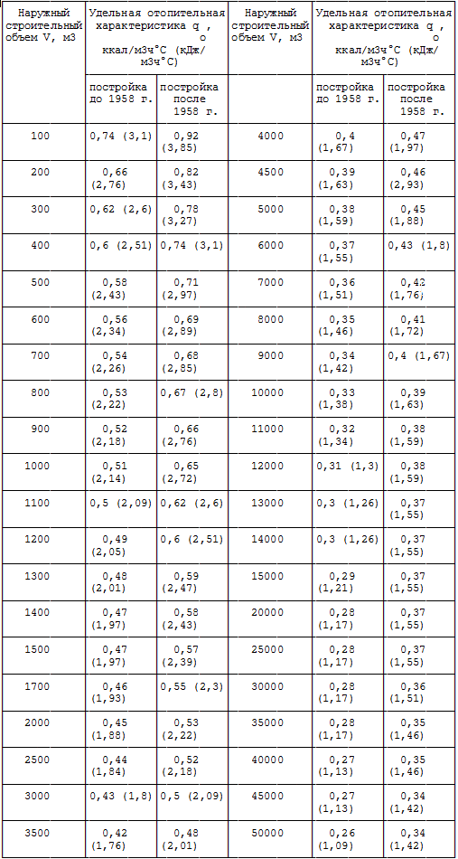
Depending on the volume of the building and its purpose, we determine their specific heating and ventilation characteristics according to the source [2]. We summarize the data in Table 2.
Table 2 - Heating and ventilation characteristics of buildings
| Building no. | Purpose | Dimensions, m | V m3 | Specific thermal characteristics, kJ/m3 h °C |
| qо | qв | |||
| 80 sq. and. house (5 floors) | 74x18x15 | 1,55 | — | |
| 80 sq. and. house (5 floors) | 74x18x15 | 1,55 | — | |
| 100 sq. and. house (5 floors) | 110x16x15 | 1,55 | — | |
| Shop (1 floor) | 54x44x4 | 1,38 | 0,33 | |
| 90sq. and. house (5 floors) | 80x16x15 | 1,55 | — |
Heat consumption for heating is determined by the formula
Qо=(1+µ)×qо×(tв-tн.о.)×V, (1)
where µ is the infiltration coefficient, which takes into account the share of heat consumption for heating the outside air entering the room through leaks in external fences, for residential and public buildings;
K – correction factor depending on the outside air temperature, adopted from the source [2];
qo is the specific heating characteristic of the building, kJ/m3×h×oC;
tb is the internal air temperature, °C, taken from the source [2];
tno - outside air temperature for heating design, °C;
V – construction volume of the building, m3.
We summarize the calculation in Table 3.
Table 3 - Heat consumption for heating
| Building no. | 1+µ | K | q o, kJ/m3·h·оС. | tв, оС | tn.o., oC | V, m3 | Qо |
| kJ/h | kW | ||||||
| 1,05 | 1,06 | 1,55 | -26 | ||||
| 1,05 | 1,06 | 1,55 | -26 | ||||
| 1,05 | 1,06 | 1,55 | -26 | ||||
| 1,05 | 1,06 | 1,38 | -26 | ||||
| 1,05 | 1,06 | 1,55 | -26 |
Heat consumption for ventilation Qv, kJ/kg, is determined by the formula:
Qв=qв×(tв-tнв)×V, (2)
where qv is the specific ventilation characteristic of the building, kJ/m3× h×oC;
tнв - outside air temperature for ventilation design, оС;
tв - internal air temperature, °C;
V – construction volume of the building, m3.
We summarize the calculation in Table 4.
Table 4 - Heat consumption for ventilation
| Building no. | qv kJ/m3×h×oC | tв,оС | tnvoS | V, m3 | Qв |
| kJ/h | kW | ||||
| 0,33 | -26 |
Heat consumption for hot water supply is determined by the formula, kJ/h
| Q |
(3)
where m is the estimated number of consumers, for residential buildings it is assumed that 4 people live in the apartment;
a is the rate of hot water consumption, l/day, taken from the source [3];
с – heat capacity of water, с=4.19 kJ/h×оС;
tg – hot water temperature, tg = 55 oC;
tх – cold water temperature, tх = 5 оС;
n – number of hours of load use;
K is the coefficient of unevenness hours, taken from the source [4].
The calculation is summarized in Table 5.
Table 5 - Heat consumption for hot water supply
| Building no. | m, people | a, l/day | tgoS | txoC | n | K | Qg.v. |
| kJ/h | kW | ||||||
| 3,595 | |||||||
| 3,595 | |||||||
| 3,45 | |||||||
| 3,53 |
Determine the total heat consumption
∑Qо= Qо1+ Qо2+… Qоn, kW, (4)
∑Qв= Qв1+ Qв2+… Qвn, kW, (5)
∑Qgv= Qo1+ Qgv2+… Qgvn, kW. (6)
We summarize the calculation in Table 6.
Table 6 - Total heat consumption
| Building no. | Qо,kW | Qv,kW | Qgv,kW |
| — | |||
| — | |||
| — | |||
| — | |||
| S |
Other methods for calculating heat volume
You can calculate the amount of heat entering the heating system in other ways.
The formula for calculating heating in this case may differ slightly from the above and have two options:
- Q = ((V1 * (T1 - T2)) + (V1 - V2) * (T2 - T)) / 1000.
- Q = ((V2 * (T1 - T2)) + (V1 - V2) * (T1 - T)) / 1000.
All variable values in these formulas are the same as before.
Based on this, we can say with confidence that the calculation of kilowatts of heating can be done on your own. However, do not forget about consultation with special organizations responsible for supplying heat to homes, since their principles and calculation system may be completely different and consist of a completely different set of measures.
Having decided to construct a so-called “warm floor” system in a private house, you need to be prepared for the fact that the procedure for calculating the volume of heat will be much more complicated, since in this case it is necessary to take into account not only the features of the heating circuit, but also provide for the parameters of the electrical network from which and the floor will be heated. At the same time, the organizations responsible for monitoring such installation work will be completely different.
Many owners often face the problem of converting the required amount of kilocalories into kilowatts, which is due to the use of measuring units in the international system called “C” by many auxiliary aids. Here you need to remember that the coefficient converting kilocalories into kilowatts will be 850, that is, in simpler terms, 1 kW is 850 kcal. This calculation procedure is much simpler, since calculating the required volume of gigacalories is not difficult - the prefix “giga” means “million”, therefore, 1 gigacalorie is 1 million calories.
In order to avoid errors in calculations, it is important to remember that absolutely all modern heat meters have some error, but often within acceptable limits. The calculation of such an error can also be done independently, using the following formula: R = (V1 - V2) / (V1+V2) * 100, where R is the error of the common house heating meter
V1 and V2 are the parameters of water flow in the system already mentioned above, and 100 is the coefficient responsible for converting the resulting value into a percentage. In accordance with operational standards, the maximum permissible error may be 2%, but usually this figure in modern instruments does not exceed 1%.
Computations
It is almost impossible to calculate the exact value of heat loss for an arbitrary building. However, methods for approximate calculations have long been developed that give fairly accurate average results within the limits of statistics. These calculation schemes are often referred to as calculations based on aggregated indicators (meters).
The construction site must be designed in such a way that the energy required for cooling is minimal. While residential buildings can be excluded from structural cooling energy demand because internal heat loss is minimal, the situation in the non-residential sector is somewhat different. In such buildings, the internal thermal benefits that are required for mechanical cooling are caused by the distinctive masonry on the overall thermal gain. The workplace also needs to ensure hygienic air flow, which is largely controlled and forced.
Along with thermal power, there is often a need to calculate daily, hourly, annual thermal energy consumption or average power consumption. How to do it? Let's give a few examples.
Hourly heat consumption for heating using enlarged meters is calculated using the formula Qot=q*a*k*(tin-tno)*V, where:
- Qot - the desired value in kilocalories.
- q is the specific heating value of the house in kcal/(m3*S*hour). It is looked up in directories for each type of building.
Such drainage is also necessary during the summer period to cool down due to the removal of heat from the outside by air and the requirement for possible dehumidification. Shading in the form of overhead or horizontally-dwelling elements is a method today, but the effect is limited to times when the sun is high above the horizon. From this point of view, the most important method is extinguishing external lifts, of course with regard to daylighting.
Reducing internal thermal benefits is somewhat problematic. This will also help reduce the need for artificial lighting. Personal computer performance is steadily increasing, but significant progress has been made in this area. The need for cooling is also represented by building structures capable of storing thermal energy. Such structures are especially heavy building structures such as. concrete floor or ceiling, which can also cause internal spur accumulation, external walls or rooms.
- a is the ventilation correction factor (usually 1.05 - 1.1).
- k is the correction factor for the climatic zone (0.8 - 2.0 for different climatic zones).
- tin - internal temperature in the room (+18 - +22 C).
- tno - street temperature.
- V is the volume of the building together with the enclosing structures.
To calculate the approximate annual heat consumption for heating in a building with a specific consumption of 125 kJ/(m2*S*day) and an area of 100 m2, located in a climate zone with the GSOP=6000 parameter, you just need to multiply 125 by 100 (house area ) and by 6000 (degree days of the heating period). 125 * 100 * 6000 = 75,000,000 kJ, or approximately 18 gigacalories, or 20,800 kilowatt-hours.
It is also advantageous to use special phase shift materials at a suitable temperature. For light residential buildings without cooling, where storage capacity is minimal, problems arise in maintaining temperature conditions during the summer months.
In terms of air conditioner design, but also cooling energy requirements, it will be necessary to use accurate, affordable calculation methods. In this regard, it is possible to predict a particularly clear calculation of heat sinks. As already stated, the cooling energy requirement will be minimal in net-zero buildings. Some buildings cannot be cooled without cooling, and providing optimal parameters for workers' thermal comfort, especially in office buildings, is now standard.
To convert the annual consumption into average heat, it is enough to divide it by the length of the heating season in hours. If it lasts 200 days, the average heating power in the above case will be 20800/200/24=4.33 kW.
Calculation of heat and fuel needs
Let's consider the calculation for the attached design heat load. We have the following initial data for calculation:
1) Estimated outside air temperature tН = -280С (according to SNiP 23-01-99* “Construction climatology”).
2) Average outside air temperature during the heating period tНСР = -3.10С (according to SNiP 23-01-99* “Building climatology”).
3) Duration of the heating period n0=214 days (according to SNiP 23-01-99* “Construction climatology”).
4) Internal temperature of the premises tВН = 180С (according to MDK 4-05.2004 “Methodology for determining the need for fuel, electrical energy and water in the production and transmission of thermal energy and coolants in municipal heating systems”).
5) Attached design heating load QOT = 1.06 Gcal/h
6) Attached ventilation load QVENT = 0.76 Gcal/h
7) Connected load for hot water supply QDHW MAX = 1.39 Gcal/h
 Cold water temperature at the boiler room inlet in summer and winter tХВ = 50С
9) Hot water temperature in the hot water supply system tDHW = 600C
10) Boiler efficiency nBOILER = 0.92 (according to the technical passport of the boiler).
11) Heat consumption for the boiler room’s own needs nС.Н. = 0.995
12) Heat losses in heating networks nТ.С. = 0.96
Annual heat consumption for heating
The annual heat consumption for heating QOTYOD (Gcal/year) of buildings during round-the-clock operation is determined by the formula:
QOTYOD = QOTSR* n0*24 = QOT*(( tVN - t N SR )/( t VN - t N ))* n 0 *24 = 1.06*214*((18—(-3.1)) /(18—(—28))*24 = 2497.21 Gcal/year
Annual heat consumption for ventilation
The annual heat consumption for ventilation of public buildings QVENTYOD (Gcal/year) is determined by the formula:
QVENTYOD = QVENTSR* n0* z = QVENT*(( tVN - t N SR )/( t VN - t N.VENT ))* n 0 * z = 0.76*214*((18—(—3.1 ))/(18—(—15))*16=1663.86 Gcal/year
z is the average number of hours of operation of the ventilation system of public buildings during the heating period during the day, hours (in the absence of data, we take z = 16 hours).
Annual heat consumption for hot water supply
The annual heat consumption for hot water supply QGVSGOD (Gcal/year) is determined by the formula:
QDHWGYD= QDHW SUMMER.N.+ QDHW WINSR.N.=(350 - n 0 )* Q DHW SR *24+24* Q DHW SR * n 0 = (350—214)*1.39*24+24* 1.39*214 = 11676 Gcal/year
Annual heat consumption
QDEEMYYEAR= QYEAR+ QVENTYEAR+ QGWYEAR = 2497.21+1663.86+11676 = 15837.07 Gcal/year
The amount of heat generated by boilers per year, taking into account their own needs and losses in heating networks
QYEAR = QCONSUMED YEAR / ( nS.N.* nT.S.) = 15837.07 / (0.995*0.96) = 16579.85 Gcal/year
Annual volume of natural gas
VGAS = QYEAR/( nX* QНР) = 16579.85*106/(0.92*7600) = 2.37 million m3/year
What it is
Definition
The definition of specific heat consumption is given in SP 23-101-2000. According to the document, this is the name for the amount of heat needed to maintain a normal temperature in a building, per unit area or volume and to another parameter - the degree-day of the heating period.
What is this parameter used for? First of all, to assess the energy efficiency of a building (or, what is the same, the quality of its insulation) and plan heat costs.
Actually, SNiP 02/23/2003 directly states: the specific (per square or cubic meter) consumption of thermal energy for heating a building should not exceed the given values. The better the thermal insulation, the less energy heating requires.
Degree-day
At least one of the terms used needs clarification. What is a degree day?
This concept directly refers to the amount of heat required to maintain a comfortable climate inside a heated room in winter. It is calculated using the formula GSOP=Dt*Z, where:
- GSOP is the desired value;
- Dt is the difference between the normalized internal temperature of the building (according to current SNiP it should be from +18 to +22 C) and the average temperature of the coldest five days of winter.
- Z is the length of the heating season (in days).
As you might guess, the value of the parameter is determined by the climatic zone and for the territory of Russia varies from 2000 (Crimea, Krasnodar Territory) to 12000 (Chukchi Autonomous Okrug, Yakutia).
Units
In what quantities is the parameter of interest to us measured?
- SNiP 02/23/2003 uses kJ/(m2*S*day) and, in parallel with the first value, kJ/(m3*S*day).
- Along with the kilojoule, other units of heat measurement can be used - kilocalories (Kcal), gigacalories (Gcal) and kilowatt-hours (KWh).
How are they related?
- 1 gigacalorie = 1,000,000 kilocalories.
- 1 gigacalorie = 4,184,000 kilojoules.
- 1 gigacalorie = 1162.2222 kilowatt-hours.
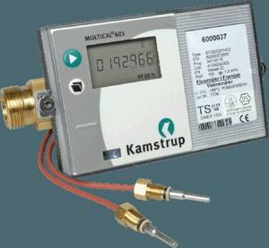
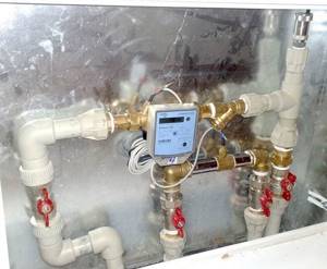
The photo shows a heat meter. Heat metering devices can use any of the listed units of measurement.
Determination of hourly and annual heat energy consumption for ventilation
The calculation of the building (building) is carried out according to aggregated indicators and is determined according to the formula: Qр в = q в x V (tв – tрн ) x 10-6, Gcal/h where: q в – specific thermal characteristic of the building, kcal (m3°С) ; V – volume of the ventilated part of the building, m3; tв – internal air temperature, °С; trn – outside air temperature for calculating ventilation systems, °C The annual consumption of thermal energy for ventilation is determined by the formula: Qyear in = Zin x Qtemp x (( Tv – Tso)/( Tv – Tn)) x Po, Gcal/year where: Qvr – maximum hourly heat consumption for ventilation, Gcal/h; Rho – duration of the heating period, days; Zв – operating time per day, h; Тсо – average temperature of outside air during the heating period, °С Тн – design temperature of outside air for designing heating and ventilation, °С Тв – design temperature of internal air of heated buildings, °С Production building V = 9248 m3; tв = 16°С; q veins = 1.21 kcal/(m3h°C); Qhour ven. = 1.21 x 9248 x (16-(-24)) = 447610 kcal/h = 0.448 Gcal/h Qyear ven. = 12 x 0.448 x(16-(-0.9)/(16-(-24)x198 = 450 Gcal/year
Heat meters
Now let’s find out what information is needed in order to calculate the heating. It's easy to guess what this information is.
1. Temperature of the working fluid at the outlet/inlet of a specific section of the pipeline.
2. The flow rate of the working fluid that passes through the heating devices.
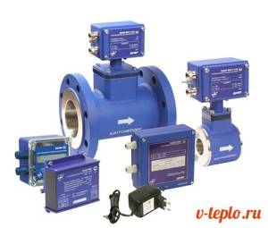
Consumption is determined through the use of heat metering devices, that is, meters. These can be of two types, let’s get acquainted with them.
Vane meters
Such devices are intended not only for heating systems, but also for hot water supply. Their only difference from those meters that are used for cold water is the material from which the impeller is made - in this case it is more resistant to elevated temperatures.

As for the mechanism of operation, it is almost the same:
- due to the circulation of the working fluid, the impeller begins to rotate;
- the rotation of the impeller is transmitted to the accounting mechanism;
- transmission is carried out without direct interaction, but with the help of a permanent magnet.
Despite the fact that the design of such meters is extremely simple, their response threshold is quite low, moreover, there is reliable protection against distortion of readings: the slightest attempts to slow down the impeller through an external magnetic field are stopped thanks to an antimagnetic screen.
Devices with a difference recorder
Such devices operate on the basis of Bernoulli's law, which states that the speed of a gas or liquid flow is inversely proportional to its static movement. But how does this hydrodynamic property apply to calculations of working fluid flow? It’s very simple - you just need to block its path with a retaining washer. In this case, the rate of pressure drop on this washer will be inversely proportional to the speed of the moving flow. And if the pressure is recorded by two sensors at once, then the flow can be easily determined, and in real time.
Note! The design of the meter implies the presence of electronics. The vast majority of such modern models provide not only dry information (temperature of the working fluid, its flow rate), but also determine the actual use of thermal energy
The control module here is equipped with a port for connecting to a PC and can be configured manually.
Many readers will probably have a logical question: what to do if we are not talking about a closed heating system, but about an open one, in which selection for hot water supply is possible? How to calculate Gcal for heating in this case? The answer is quite obvious: here pressure sensors (as well as retaining washers) are installed simultaneously on both the supply and the “return”. And the difference in the flow rate of the working fluid will indicate the amount of heated water that was used for domestic needs.
Heat meters
In order to calculate thermal energy you need to know the following information:
- The temperature of the liquid at the inlet and outlet of a certain section of the pipeline.
- The flow rate of liquid that moves through heating devices.
Consumption can be determined using heat meters. Heat meters can be of two types:
- Vane counters. Such devices are used to measure thermal energy, as well as hot water consumption. The difference between such meters and devices for metering cold water is the material from which the impeller is made. In such devices it is most resistant to high temperatures. The operating principle is similar for the two devices:
- The rotation of the impeller is transmitted to the metering device;
- The impeller begins to rotate due to the movement of the working fluid;
- The transfer is carried out without direct interaction, but with the help of a permanent magnet.
Such devices have a simple design, but their response threshold is low. They also have reliable protection against reading distortion. Using an antimagnetic screen, the impeller is prevented from braking by the external magnetic field.
- Devices with a difference recorder. Such meters operate according to Bernoulli's law, which states that the speed of a liquid or gas flow is inversely proportional to its static movement. If the pressure is recorded by two sensors, the flow can be easily determined in real time. The counter involves electronics in the design. Almost all models provide information on the flow and temperature of the working fluid, and also determine the consumption of thermal energy. You can configure the work manually using a PC. You can connect the device to a PC via a port.
Many residents are wondering how to calculate the amount of Gcal for heating in an open heating system in which hot water can be selected. Pressure sensors are installed on the return and supply pipes at the same time. The difference in the flow rate of the working fluid will show the amount of warm water that was spent for domestic needs.
Hydraulic calculation
So, the heat loss has been determined, the power of the heating unit has been selected, all that remains is to determine the volume of the required coolant, and, accordingly, the dimensions, as well as the materials of the pipes, radiators and shut-off valves used.
First of all, we determine the volume of water inside the heating system. This requires three indicators:
- Total power of the heating system.
- Temperature difference at the outlet and inlet of the heating boiler.
- Heat capacity of water. This figure is standard and equal to 4.19 kJ.
Hydraulic calculation of the heating system
The formula is as follows: divide the first indicator by the last two. By the way, this type of calculation can be used for any part of the heating system
Here it is important to divide the line into parts so that in each the speed of movement of the coolant is the same. Therefore, experts recommend making a breakdown from one shut-off valve to another, from one heating radiator to another
Now we move on to calculating coolant pressure losses, which depend on friction inside the pipe system. To do this, only two quantities are used, which are multiplied together in the formula. This is the length of the main section and specific friction losses.
But pressure losses in shut-off valves are calculated using a completely different formula. It takes into account indicators such as:
- Coolant density.
- Its speed in the system.
- The total indicator of all coefficients that are present in this element.
In order for all three indicators, which are derived by formulas, to fit standard values, it is necessary to select the correct pipe diameters. For comparison, we will give an example of several types of pipes to make it clear how their diameter affects the heat output.
- Metal-plastic pipe with a diameter of 16 mm. Its thermal power varies in the range of 2.8-4.5 kW. The difference in the indicator depends on the temperature of the coolant. But keep in mind that this is a range where the minimum and maximum values are set.
- The same pipe with a diameter of 32 mm. In this case, the power varies between 13-21 kW.
- Polypropylene pipe. Diameter 20 mm - power range 4-7 kW.
- The same pipe with a diameter of 32 mm - 10-18 kW.
And the last thing is the definition of a circulation pump. In order for the coolant to be evenly distributed throughout the heating system, it is necessary that its speed be no less than 0.25 m/sec and no more than 1.5 m/sec. In this case, the pressure should not be higher than 20 MPa. If the coolant velocity is higher than the maximum suggested value, the pipe system will operate noisily. If the speed is lower, airing of the circuit may occur.
Hydraulic calculations for a heating system
Calculations of this type help to correctly select pipes for the heating system, in particular, determine their length and cross-section. The efficiency of the system also depends on this, since the main parameters of the pumping equipment can be easily calculated.
Hydraulic calculations are necessary to determine the following parameters:
Water consumption in the heating system. To do this, use the formula:
M = Q/Cp*DPt,
where Q is the total power of the heating system, Cp is the specific heat capacity of water, which in most cases is equal to 4.19 KJ, DPt is the difference between the temperatures at the inlet and outlet of the boiler.
To determine the water flow in one of the pipeline sections, you can use a similar method. In this case, you should choose areas with the same coolant velocity. Then the total power of all heating devices is determined and substituted into the formula
It is important to calculate all areas between radiators. The formula for calculating thermal energy is also important and should also be used.
A known amount of coolant flow in the system allows one to determine its speed. For this, the following formula is used:
V = M/P*F.
Here M is the coolant flow rate in a certain area, P is an indicator of its density, F is the cross-sectional area of the pipe. To determine the last parameter, the formula is used: 3.14r/2, where the letter r denotes the internal diameter of the pipe.
Coolant pressure loss due to friction in the pipe. This parameter can be calculated using the formula:
DPptp = R*L.
Here the letter R denotes specific friction losses, L is the length of the pipe section.
In addition, it is necessary to calculate the pressure reduction in places where the coolant encounters an obstacle, in particular we are talking about various shut-off valves and fittings. For the calculation, there is also a certain formula in which it is necessary to multiply the density of water, its speed and the total sum of the resistance coefficients in a certain area.
Having added the values in each section between heating devices, it is important to compare the result obtained with the control parameters. For the circulation pump to operate effectively, the pressure loss on long sections of the pipeline should not be more than 20 kPa, and the water movement speed should be no more than 1.5 meters per second
At higher values, the coolant will move very noisily. In addition, according to Sanitary Standards, the specified coolant speed prevents the appearance of air in the system.
Standard heating consumption per sq. m.
hot water supply
1 2 3
1.
Multi-apartment residential buildings equipped with centralized heating, cold and hot water supply, drainage with showers and baths
Length 1650-1700 mm 8.12 2.62
Length 1500-1550 mm 8.01 2.56
Length 1200 mm 7.9 2.51
2.
Multi-apartment residential buildings equipped with centralized heating, cold and hot water supply, drainage with showers without bathtubs
7.13 2.13 3. Multi-apartment residential buildings equipped with centralized heating, cold and hot water supply, drainage without showers and baths 5.34 1.27
4.
Standards for the consumption of utilities in Moscow
| No. | Name of company | Tariffs including VAT (rubles/cubic m) | |
| cold water | drainage | ||
| 1 | JSC "Mosvodokanal" | 35,40 | 25,12 |
Note. Tariffs for cold water and sewerage for the population of the city of Moscow do not include commission fees charged by credit institutions and payment system operators for services for accepting these payments.
Heating standards per 1 square meter
It should be remembered that you do not need to make calculations for the entire apartment, because each room has its own heating system and requires an individual approach. In this case, the necessary calculations are made using the formula: C*100/P=K, where K is the power of one section of your radiator battery, as stated in its characteristics; C is the area of the room.
What are the standards for the consumption of utilities in Moscow in 2021?
No. 41 “On the transition to a new system of payment for housing and utilities and the procedure for providing housing subsidies to citizens”, the indicator for heat supply applies:
- heat energy consumption for heating the apartment – 0.016 Gcal/sq. m;
- water heating – 0.294 Gcal/person.
Residential buildings equipped with sewerage, running water, baths with hot central water supply:
- water disposal - 11.68 m³ per person per month;
- hot water – 4.745.
- cold water – 6.935;
Housing equipped with sewerage, running water, baths with gas heaters:
- water disposal – 9.86;
- cold water – 9.86.
Houses with running water with gas heaters near the bathtubs and sewerage:
- 9.49 m³ per 1 person per month.
- 9,49;
Residential buildings of hotel type, equipped with running water, hot water supply, gas:
- cold water – 4.386;
- hot – 2,924.
- water disposal – 7.31;
Utility consumption standards
Payment for electricity, water supply, sewerage and gas is made according to established standards if an individual meter is not installed.
- From July 1 to December 31, 2015 – 1.2.
- From January 1 to June 30, 2021 – 1.4.
- From July 1 to December 31, 2021 – 1.5.
- From 2021 – 1.6.
- From January 1 to June 30, 2015 – 1.1.
Thus, if you do not have a collective heat meter installed in your house, and you pay, for example, 1 thousand rubles a month for heating, then from January 1, 2015 the amount will increase to 1,100 rubles, and from 2021 - to 1,600 rubles
Calculation of heating in an apartment building from 01/01/2019
The calculation methods and examples presented below provide an explanation of the calculation of the heating fee for residential premises (apartments) located in apartment buildings with centralized systems for supplying thermal energy.
How many Gcal is needed for heating 1 sq m Standard 2021
Be that as it may, heating standards are not observed, so consumers have every right to file a corresponding complaint and demand a recalculation of tariff plans. The choice of one or another calculation method depends on whether a heat meter is installed in the house or apartment.
In the absence of a general house meter, tariffs are calculated according to standards, and those, as we have already found out, are determined by local authorities.
This is done through a special decree, which also determines the payment schedule - whether you will pay all year round or exclusively during the heating season.
How are heating charges calculated in an apartment building?
- the commissioned communal heat metering unit failed and was not repaired within 2 months;
- the heat meter is stolen or damaged;
- readings from the home appliance are not transmitted to the heat supply organization;
- access of the organization's specialists to the house meter in order to check the technical condition of the equipment is not provided (2 visits or more).
As an example of calculation, let’s take our apartment of 36 m² and assume that in a month an individual meter (or a group of individual meters) “accumulated” 0.6, a house meter – 130, and a group of devices in all rooms of the building gave a total of 118 Gcal. We leave the remaining indicators the same (see previous sections). How much does heating cost in this case?