Potapov's heat generator is not known to the general public and has not yet been studied enough from a scientific point of view. For the first time, Yuri Semenovich Potapov dared to try to implement the idea that came to mind towards the end of the eighties of the last century. The research was carried out in the city of Chisinau. The researcher was not mistaken, and the results of the attempts exceeded all his expectations.
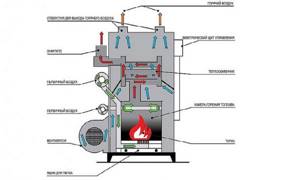
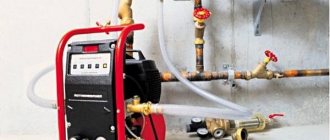
Diagram of a solid fuel heat generator.
The finished heat generator was patented and put into general use only at the beginning of February 2000.
All existing opinions regarding the heat generator created by Potapov differ quite greatly. Some consider it to be an almost worldwide invention; they attribute to it very high operating efficiency - up to 150%, and in some cases up to 200% energy savings. It is believed that an inexhaustible source of energy has been practically created on Earth without harmful consequences for the environment. Others argue the opposite - they say that all this is quackery, and the heat generator, in fact, requires even more resources than when using its standard analogues.
According to some sources, Potapov’s developments are prohibited in Russia, Ukraine and Moldova. According to other sources, at the moment, in our country, thermogenerators of this type are produced by several dozen factories and they are sold all over the world; they have long been in demand and take prizes at various technical exhibitions.
Operating principle
For a long time, many people thought that cavitation is a parasitic phenomenon characterized by the formation of bubbles, which, in the process of collapse, provoke the destruction of surrounding objects. A vortex-type heat generator is a device in which the parasitic phenomenon is beneficial.
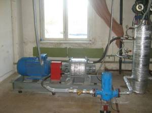
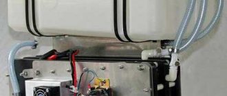
Potapov heat generator connected to a heating radiator
Cavitation subsequently makes it possible not to give heat to the water, but to extract it from moving water, heating it to significant temperatures. Cavitation is a parasitic phenomenon, but despite this, the structural elements of modern heat generators do not suffer. In this case, cavitation processes do not occur around the disk activator, but behind it.
Operating principle of the cavitation converter
Process description:
- The main flow of liquid medium at normal temperature is supplied to the converter.
- Additional flows of liquid medium are supplied towards the main flow.
- Multidirectional flows colliding create the effect of cavitation. Due to this, the liquid medium at the outlet of the converter is heated.
Design and operation
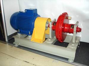
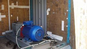
If we consider the design of existing samples of vortex heat generators, then we can see that it is simple. They are a massive engine to which a cylindrical “snail” device is connected.
The "snail" is considered a modified version of Ranque's trumpet. It has a characteristic shape, so the intensity of cavitation processes is much higher compared to a vortex tube. In the cavity of the cochlea there is a disk activator - this is a disk with a special perforation. When the disk rotates, the liquid medium is activated due to which cavitation processes will occur:
- The electric motor turns the disk activator. According to experts, the disk activator is the most important element in the installation, and it is connected to the electric motor via a straight shaft. When the device is turned on in operating mode, the engine transmits torque to the activator.
- The activator spins the liquid medium. The design of the activator was developed in such a way that, when the liquid medium enters the disk cavity, it acquires kinetic energy.
- The process of converting mechanical energy into thermal energy. As the liquid leaves the activator, the medium will lose acceleration and, as a result of sudden braking, a cavitation effect occurs. As a result of such manipulations, kinetic energy heats the liquid medium to +95 degrees, and mechanical energy becomes thermal.
History of creation
French scientists then treated this invention with distrust and ridiculed the report of J. Ranquet, made in 1933 at a meeting of the French Physical Society. For, according to these scientists, the work of the vortex tube, in which the air supplied to it was divided into hot and cold flows like a fantastic “Maxwell’s demon,” contradicted the laws of thermodynamics. Nevertheless, the vortex tube worked and later found wide application in many fields of technology, mainly for producing cold.
For us, the most interesting work is the work of Leningrader V. E. Finko, who drew attention to a number of paradoxes of the vortex tube, developing a vortex gas cooler to obtain ultra-low temperatures. He explained the process of gas heating in the near-wall region of the vortex tube by the “mechanism of wave expansion and compression of gas” and discovered infrared radiation of gas from its axial region, which has a band spectrum, which later helped us understand the operation of Potapov’s vortex heat generator.
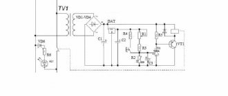
In a Ranke vortex tube, the diagram of which is shown in Figure 1, a cylindrical pipe 1 is connected at one end to a volute 2, which ends with a nozzle input of rectangular cross-section, which supplies compressed working gas into the pipe tangentially to the circumference of its inner surface. At the other end, the snail is closed by a diaphragm 3 with a hole in the center, the diameter of which is significantly smaller than the internal diameter of pipe 1. Through this hole, a cold gas flow exits pipe 1, which is divided during its vortex movement in pipe 1 into cold (central) and hot (peripheral) parts. The hot part of the flow adjacent to the inner surface of pipe 1, rotating, moves to the far end of pipe 1 and leaves it through the annular gap between its edge and the adjusting cone 4.
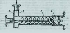
Figure 1. Ranke vortex tube: 1-tube; 2- snail; 3- diaphragm with a hole in the center; 4-adjustment cone.
A complete and consistent theory of the vortex tube still does not exist, despite the simplicity of this device. “Basically” it turns out that when a gas spins in a vortex tube, under the influence of centrifugal forces it is compressed at the walls of the pipe, as a result of which it heats up here, just as it heats up when compressed in a pump. In the axial zone of the pipe, on the contrary, the gas experiences a vacuum, and here it cools and expands. By removing gas from the near-wall zone through one hole, and from the axial zone through another, the separation of the initial gas flow into hot and cold flows is achieved.
Liquids, unlike gases, are practically incompressible. Therefore, for more than half a century, no one even thought of feeding water into a vortex tube instead of gas or steam. And the author decided on a seemingly hopeless experiment - he fed water from the water supply into the vortex tube instead of gas.
To his surprise, the water in the vortex tube divided into two streams having different temperatures. But not hot and cold, but hot and warm. Because the temperature of the “cold” flow turned out to be slightly higher than the temperature of the source water supplied by the pump to the vortex tube. Careful calorimetry showed that such a device produces more thermal energy than is consumed by the electric motor of the pump supplying water to the vortex tube.
This is how Potapov’s heat generator was born.
Generator insulation
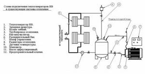
Connection diagram of the heat generator to the heating system.
First you need to make the insulation casing. For this, take a sheet of galvanized sheet or thin aluminum. Cut two rectangles out of it if you are making a casing from two halves. Or one rectangle, but in such a way that after manufacturing it will completely fit the Potapov vortex heat generator, which you assembled with your own hands.
It is best to bend the sheet on a large diameter pipe or use a cross member. Place the cut sheet on it and press the wooden block on top with your hand. With your second hand, press the sheet of tin so that a small bend is formed along its entire length. Advance the workpiece a little and repeat the operation again. Do this until you get a cylinder.
- Connect it using a lock, which is what tinsmiths use for drainpipes.
- Make covers for the casing, providing holes in them for connecting the generator.
- Wrap the device with insulating material. Using wire or thin strips of tin, secure the insulation.
- Place the device in the casing and close the lids.
There is another way to increase heat production: to do this, you need to understand how the Potapov vortex generator works, the efficiency of which can approach 100% and higher (there is no consensus on why this happens).
As water passes through the nozzle or nozzle, a powerful stream is created at the outlet, which hits the opposite end of the device. It twists, and heating occurs due to the friction of the molecules. This means that by placing an additional barrier inside this flow, you can increase the mixing of the liquid in the device.
Once you know how it works, you can begin to design additional improvements. This will be a vortex damper made of longitudinal plates located inside two rings in the form of an aircraft bomb stabilizer.
Scheme of a stationary heat generator.
Tools: welding machine, angle grinder.
Materials: sheet metal or strip iron, thick-walled pipe.
Make two rings 4-5 cm wide from a pipe of smaller diameter than Potapov’s vortex heat generator. Cut identical strips from strip metal. Their length should be equal to a quarter of the length of the body of the heat generator itself. Select the width so that after assembly there is a free hole inside.
- Secure the plate in a vice. Hang rings on it on one side and the other. Weld a plate to them.
- Remove the workpiece from the clamp and turn it 180 degrees. Place the plate inside the rings and secure it in the clamp so that the plates are opposite each other. Fix 6 plates in this way at equal distances.
- Assemble the vortex heat generator by inserting the described device opposite the nozzle.
Probably, this product can be further improved. For example, instead of parallel plates, use steel wire, winding it into an air ball. Or make holes of different diameters on the plates. Nothing is said about this improvement anywhere, but this does not mean that it is not worth doing.
Principle of operation
"Cavitation" refers to the formation of bubbles in a liquid, such that the impeller operates in a mixed phase (liquid and gas bubble period) of the environment. Pumps, as a rule, are not designed for mixed phase flow (their operation destroys bubbles, causing the cavitation generator to lose efficiency). These thermal devices are designed to induce mixed phase flow as part of fluid mixing, resulting in thermal conversion.
Photo – Heat generator drawing
In commercial cavitation heaters, mechanical energy drives the input energy heater (eg, motor, control unit), causing the fluid that produces the output energy to return to the source. This storage converts mechanical energy into thermal energy with little loss (usually less than 1 percent), so conversion errors are taken into account when converting.
A supercavitation jet energy generator works a little differently. Such a heater is used in high-power enterprises, when the thermal energy output is transferred to a liquid in a certain device, its power significantly exceeds the amount of mechanical energy required to operate the heater. These devices are more energy efficient than return mechanisms, in particular because they do not require regular checking and adjustment.
There are different types of such generators. The most common type is the rotary hydrodynamic Griggs mechanism. Its operating principle is based on the operation of a centrifugal pump. It consists of pipes, a stator, a housing and a working chamber. At the moment, there are many upgrades, the simplest is a rotary drive or disk (spherical) water pump. It is a disk surface in which many different blind-type holes are drilled (without exit), these structural elements are called Griggs cells. Their dimensional parameters and number directly depend on the rotor power, the design of the heat generator and the drive speed.
Photo – Griggs hydrodynamic mechanism
There is a certain gap between the rotor and stator, which is necessary for heating the water. This process is carried out by rapid movement of liquid along the surface of the disk, which increases the temperature. On average, the rotor moves at approximately 3,000 rpm, which is enough to raise the temperature to 90 degrees.
The second type of cavitation generator is usually called static. Unlike a rotary one, it does not have any rotating parts; in order for cavitation to occur, it needs nozzles. In particular, these are parts of the famous Laval, which are connected to the working chamber.
To operate, a conventional pump is connected, as in a rotary generator, it pumps up pressure in the working chamber, which ensures a higher speed of water movement, and, accordingly, an increase in its temperature. The fluid velocity at the nozzle exit is ensured by the difference in the diameters of the forward and outlet pipes. Its disadvantage is that the efficiency is significantly lower than in a rotary one, especially since it is larger and heavier.
Talking about perpetual motion machines: scientific fables
Victor Schauberger
The Austrian physicist Viktor Schauberger, when he was a forester, developed an interesting system for alloying logs. In appearance it resembled the bends of natural rivers, rather than a straight line. Moving along such a unique trajectory, the tree reached its destination faster. Schauberger explained this by reducing the forces of hydraulic friction.
Rumor has it that Schauberger became interested in the vortex motion of fluid. Austrian beer drinkers would spin the bottle in competitions to give the drink a spinning motion. The beer flew into the belly faster, the cunning one won. Schauberger repeated the trick himself and was convinced of its effectiveness.
The described case should not be confused with a vortex of waste water, which always swirls in one direction. The Coriolis force is caused by the rotation of the Earth and is believed to have been noticed by Giovanni Battista Riccioli and Francesco Maria Grimaldi in 1651. The phenomenon was explained and described in 1835 by Gaspar-Gustav Coriolis. At the initial moment of time, due to the random movement of the water flow, it moves away from the center of the funnel, and the trajectory twists in a spiral. Due to water pressure, the process gains strength and a cone-shaped depression is formed on the surface.
Viktor Schauberger approximately on May 10, 1930 received an Austrian patent number 117749 for a turbine of a specific design in the form of a pointed drill. According to the scientist, in 1921, a generator was made on its basis, which supplied energy to an entire farm. Schauberger claimed that the efficiency of the device was close to 1000% (three zeros).
Everything else about Viktor Schauberger amounts to science fiction. He was said to have invented the Repulsion engine, which powered the flying saucer that defended Berlin during World War II. At the end of hostilities, he was commissioned and refused to share his own discoveries, which could bring great harm to peace on Earth. His story is like two peas in a pod, reminiscent of what happened to Nikola Tesla.
It is believed that Schauberger assembled the first cavitation heat generator. There is a photo where he stands next to this “stove”. In one of his last letters he claimed that he had discovered new substances that made incredible things possible. For example, water purification. At the same time, claiming that his views would shake the foundations of religion and science, he predicted victory for the “Russians.” Today it is difficult to judge how close to reality the scientist remained six months before his death.
Richard Klem and the Vortex Engine
Richard Clem, in his own words, tested an asphalt pump at the end of 1972. He was alarmed by the strange behavior of the machine after it was turned off. Having begun experiments with hot oil, Richard quickly came to the conclusion that there was something like a perpetual motion machine. A specially shaped rotor made of a cone cut through spiral channels is equipped with diverging nozzles. Spun up to a certain speed, it maintained movement, managing to activate the oil pump.
The Dallas native planned a 600-mile (1,000 km) test run to El Paso, then decided to publish the invention, but only made it as far as Abilene, blaming the failure on a weak shaft. The notes on this say that the cone had to be spun up to a certain speed and the oil had to be heated to 150 degrees Celsius in order for everything to work. The device averaged 350 horsepower and weighed 200 pounds (90 kg).
The pump operated at a pressure of 300 - 500 pounds per square inch (20 - 30 atm.), and the higher the oil density, the faster the cone rotated. Richard soon died, and the work was confiscated. Patent number US3697190 for an asphalt pump is easy to find on the Internet, but Clem did not reference it. There is no guarantee that a “workable” version has not previously been removed from the bureau’s documentation. Enthusiasts still build Clem engines today and demonstrate the operating principle on YouTube.
Of course, this is only a semblance of a design; the product is incapable of creating free energy for itself. Clem said that the first engine was no good, and he had to go through 15 companies in search of financing. The motor runs on frying oil; car temperatures cannot withstand temperatures of 300 degrees. According to reporters, the 12 V battery is considered to be the only visible power source for the device.
The engine was put into cavitation mode for a simple reason: periodically the already hot oil needed to be cooled through a heat exchanger. Therefore, something inside was doing work. On reflection, the researchers attributed this to the effect of cavitation at the entrance to the pump and inside the distribution tube system. Let us emphasize: “Not a single Richard Klem engine manufactured today is functional.”
Despite this, the Russian Energy Agency published information in the database (energy.csti.yar.ru/documents/view/3720031515) with the caveat that the design of the engine(s) resembles Nikola Tesla’s turbine.
What is cavitation
Cavitation is a negative phenomenon that occurs due to a pressure difference in a liquid. When the water pressure drops to the value of the saturated vapor pressure, this leads to boiling. This is when the liquid partially turns into a vapor state, that is, bubbles form. When the pressure rises to a level above the saturated vapor value, the bubbles burst. As a result of the explosion, local pressure waves of up to 7 thousand bar occur. These pressure waves are called cavitation.
Consequences of cavitation:
- metal erosion;
- pitting corrosion;
- the appearance of vibrations.
The inventors of the cavitation generator claim that they were able to benefit from this negative phenomenon.
Do it yourself?
You can buy a ready-made cavitation heat generator, but it is unlikely to be possible to make this device yourself according to the drawings. At best, the result will be a noisy machine in which there will be no cavitation. In addition, before doing anything, you need to ask yourself the question: “Why?” There are many ways to heat your home:
Consequences of cavitation.
gas, solid fuel, in tandem with water heating systems;
Scope of application
| Illustration | Description of application |
| Heating . Equipment that converts the mechanical energy of water movement into heat is successfully used in heating various buildings, from small private buildings to large industrial facilities. By the way, in Russia today you can already count at least ten settlements where centralized heating is provided not by traditional boiler houses, but by gravity generators. |
| Heating running water for domestic use . The heat generator, when connected to the network, heats the water very quickly. Therefore, such equipment can be used to heat water in an autonomous water supply system, in swimming pools, bathhouses, laundries, etc. |
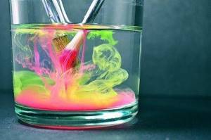
| Mixing immiscible liquids . In laboratory conditions, cavitation units can be used for high-quality mixing of liquid media with different densities until a homogeneous consistency is obtained. |

Integration into the heating system of a private home
In order to use a heat generator in a heating system, it must be installed into it. How to do this correctly? In fact, there is nothing complicated about it.
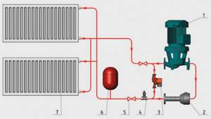
In front of the generator (marked 2 in the figure) a centrifugal pump (1 in the figure) is installed, which will supply water with a pressure of up to 6 atmospheres. After the generator, an expansion tank (6 in the figure) and shut-off valves are installed.
Advantages of using cavitation heat generators
| Advantages of a vortex source of alternative energy | |
| Economical . Thanks to the efficient consumption of electricity and high efficiency, the heat generator is more economical compared to other types of heating equipment. |
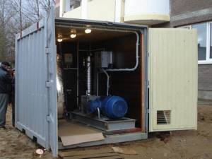
| Small dimensions compared to conventional heating equipment of similar power . A stationary generator, suitable for heating a small house, is twice as compact as a modern gas boiler. If you install a heat generator in a regular boiler room instead of a solid fuel boiler, there will be a lot of free space left. |
| Low installation weight . Due to its light weight, even large high-power installations can be easily placed on the floor of the boiler room without building a special foundation. There are no problems at all with the location of compact modifications. |
| Simple design . The cavitation type heat generator is so simple that there is nothing to break in it. The device has a small number of mechanically moving elements, and there are no complex electronics at all. Therefore, the likelihood of device failure, in comparison with gas or even solid fuel boilers, is minimal. |
| There is no need for additional modifications . The heat generator can be integrated into an existing heating system. That is, there is no need to change the diameter of the pipes or their location. |
| No need for water treatment . If a running water filter is needed for normal operation of a gas boiler, then by installing a cavitation heater, you don’t have to worry about blockages. Due to specific processes in the working chamber of the generator, blockages and scale do not appear on the walls. |
| Equipment operation does not require constant monitoring . If solid fuel boilers need to be looked after, the cavitation heater operates in autonomous mode. The operating instructions for the device are simple - just plug in the engine and, if necessary, turn it off. |
| Environmental friendliness . Cavitation installations do not affect the ecosystem in any way, because the only energy-consuming component is the electric motor. |


Installing the pump
Next we must choose the “right” water pump. The range of these tools today is so wide that you can find a model of any strength and size.
We only need to pay attention to two things:
- Will the engine be able to spin this pump;
- Is it (the pump) centrifugal?
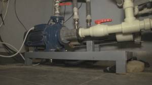
Next, the pump is installed in the same frame; if necessary, additional fasteners are attached.
The body of a vortex generator is a cylinder, closed on both sides. There should be through holes on the sides through which the device will be connected to the heating system. But the main feature of the design is inside the body: a nozzle is located immediately near the inlet. The nozzle hole must be selected purely individually.
Note! It is desirable that the nozzle hole be half as large as 1/4 of the total diameter of the cylinder. If the hole is smaller, then water will not be able to pass through it in the required quantity and the pump will begin to heat up.
Moreover, internal elements will begin to be destroyed by cavitation.
To make the case we will need the following tools:
- Iron pipe with thick walls with a diameter of about 10 cm;
- Couplings for connection;
- Welding;
- Several electrodes;
- Impeller;
- A pair of pipes with threads;
- Electric drill;
- Drill;
- Adjustable wrench.
Now - directly to the manufacturing process.
- To begin with, we cut off a piece of pipe about 50-60 cm long and make an external groove on its surface about half the thickness, 2-2.5 cm. We cut the thread.
- We take two more pieces of the same pipe, each 5 cm long, and make a couple of rings from them.
- Then we take a metal sheet with the same thickness as the pipe, cut out original covers from it, and weld them where the thread was not made.
- We make two holes in the center of the covers - one of them around the circumference of the pipe, the second around the circumference of the nozzle. Inside the cover next to the jet we drill a chamfer so that we get a nozzle.
- We connect the generator to the heating system. We connect the pipe near the nozzle to the pump, but only to the hole from which water flows under pressure. We connect the second pipe to the entrance to the heating system, but the output must be connected to the pump inlet.
The pump will create pressure, which, acting on the water, will force it to pass through the nozzle of our design. In a special chamber, the water will overheat due to active mixing, after which it is supplied directly to the heating circuit. In order to be able to regulate the temperature, the vortex heat generator must be equipped with a special locking device located next to the pipe. If you slightly cover the constipation, the structure will take longer to move water through the chamber, therefore, the temperature will rise because of this. This is how this kind of heater works.
Read about other alternative heating methods here
Pump installation
Now you will need to select a water pump. Now in specialized stores you can purchase a unit of any modification and power. What should you pay attention to?
- The pump must be centrifugal.
- Your engine will be able to spin it.
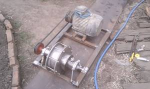
Install a pump on the frame; if you need to make more cross members, make them either from a corner or from strip iron of the same thickness as the corner. It is hardly possible to make a coupling without a lathe. Therefore, you will have to order it somewhere.
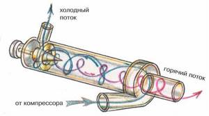
Diagram of a hydraulic vortex heat generator.
Potapov's vortex heat generator consists of a housing made in the form of a closed cylinder. At its ends there must be through holes and pipes for connection to the heating system. The secret of the design is inside the cylinder. There should be a nozzle behind the inlet hole. Its hole is selected individually for a given device, but it is desirable that it be half the size of a quarter of the diameter of the pipe body. If you do less, the pump will not be able to pass water through this hole and will begin to heat up. In addition, internal parts will begin to rapidly deteriorate due to the phenomenon of cavitation.
Tools: angle grinder or hacksaw, welding machine, electric drill, adjustable wrench.
Materials: thick metal pipe, electrodes, drills, 2 threaded pipes, couplings.
- Cut a piece of thick pipe with a diameter of 100 mm and a length of 500-600 mm. Make an external groove on it approximately 20-25 mm and half the thickness of the pipe. Cut the thread.
- Make two rings 50 mm long from the same pipe diameter. Cut an internal thread on one side of each half ring.
- Make covers from the same thickness of flat metal as the pipe and weld them on the unthreaded side of the rings.
- Make a central hole in the covers: one with the diameter of the nozzle, and the other with the diameter of the pipe. Make a chamfer on the inside of the cover, where the jet is located, with a larger diameter drill. The result should be a nozzle.
- Connect the heat generator to the system. Connect the pipe where the nozzle is located to the pump into the hole from which water is supplied under pressure. Connect the heating system input to the second pipe. Connect the outlet from the system to the pump inlet.
Water under the pressure created by the pump will pass through the nozzle of the vortex heat generator, which you make yourself. In the chamber it will begin to heat up due to intense stirring. Then feed it into the heating system. To regulate the temperature, install a ball locking device behind the nozzle. Cover it, and the vortex heat generator will circulate water inside the housing longer, which means the temperature in it will begin to rise. This is roughly how this heater works.
Operating principle of the Potapov heat generator
Diagram of a heat gun.
To fully understand all the subtleties in the nature of the operation of a device such as a heat generator, all stages of the liquid heating process should be considered step by step.
In the heat generator system, the pump creates a pressure of 4 to 6 atm. Under the created pressure, water flows under pressure into the injection pipe connected to the flange of the running centrifugal pump. A stream of liquid rapidly rushes into the cavity of the cochlea, similar to the snail in Ranque's tube. The liquid, as in the experiment done with air, begins to rotate quickly along a curved channel to achieve the cavitation effect.
The next element that contains the heat generator and where the liquid enters is a vortex tube, at this moment the water has already reached the same character and is moving rapidly. In accordance with Potapov’s developments, the length of the vortex tube is several times greater than its width. The opposite edge of the vortex tube is already hot, and the liquid is directed there.
To reach the required point, it travels its way along a helical spiral. The helical spiral is located near the walls of the vortex tube. After a moment, the liquid reaches its destination - the hot spot of the vortex tube. This action completes the movement of liquid through the main body of the device. Next, the main braking device is structurally provided. This device is designed to partially remove hot liquid from its acquired state, that is, the flow is somewhat leveled thanks to radial plates mounted on the sleeve. The sleeve has an internal empty cavity, which is connected to a small braking device following the cyclone in the heat generator structure.
Connection diagram of the heat generator to the heating system.
Along the walls of the braking device, the hot liquid moves closer and closer to the outlet of the device. Meanwhile, a vortex flow of withdrawn cold fluid flows through the inner cavity of the main brake device bushing towards the flow of hot liquid.
The contact time of the two flows through the walls of the sleeve is sufficient to heat the cold liquid. And now the warm flow is directed to the exit through a small braking device. Additional heating of the warm flow is carried out during its passage through the braking device under the influence of the phenomenon of cavitation. The well-heated liquid is ready to leave the small braking device through the bypass and pass through the main outlet pipe connecting the two ends of the main circuit of the elements of the thermal device.
The hot coolant is also directed to the outlet, but in the opposite direction. Let us remember that a bottom is attached to the upper part of the braking device; in the central part of the bottom there is a hole with a diameter equal to the diameter of the vortex tube.
The vortex tube, in turn, is connected by a hole in the bottom. Consequently, the hot liquid ends its movement through the vortex tube by passing into the bottom hole. The hot liquid then enters the main outlet pipe, where it mixes with the warm flow. This completes the movement of liquids through the Potapov heat generator system. At the outlet of the heater, water comes from the upper part of the outlet pipe - hot, and from the lower part - warm, in which it is mixed, ready for use. Hot water can be used either in the water supply for household needs, or as a coolant in the heating system. All stages of the heat generator operation take place in the presence of ether.
Advantages of heat generators when used for heating
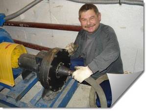
The most obvious advantage of heat generators is fairly simple maintenance, despite the possibility of free installation without requiring special permission from power grid employees. It is enough to check the rubbing parts of the device – bearings and seals – once every six months. At the same time, according to suppliers, the average guaranteed service life is up to 15 years or more.
Potapov's heat generator is completely safe and harmless to the environment and the people using it. Environmental friendliness is justified by the fact that during the operation of a cavitation heat generator, emissions of harmful products into the atmosphere from the processing of natural gas, solid fuel materials and diesel fuel are excluded. They are simply not used.
The work is powered by the electrical network. The possibility of fire due to lack of contact with open flame is excluded. Additional security is provided by the device’s instrument panel; it provides total control over all processes of temperature and pressure changes in the system.
Economic efficiency when heating a room with heat generators is expressed in several advantages. Firstly, there is no need to worry about the quality of water when it plays the role of a coolant. There is no need to think that it will harm the entire system just because of its poor quality. Secondly, there is no need to make financial investments in the arrangement, laying and maintenance of heating routes. Thirdly, heating water using physical laws and the use of cavitation and vortex flows completely eliminates the appearance of calcium stones on the internal walls of the installation. Fourthly, spending money on transportation, storage and purchase of previously necessary fuel materials (natural coal, solid fuel materials, petroleum products) is eliminated.
The undeniable advantage of heat generators for home use is their exceptional versatility. The range of applications of heat generators in everyday life is very wide:
- as a result of passing through the system, water is transformed, structured, and pathogenic microbes die under such conditions;
- You can water the plants with water from the heat generator, which will promote their rapid growth;
- the heat generator is capable of heating water to a temperature above the boiling point;
- the heat generator can work in conjunction with existing systems or be built into a new heating system;
- the heat generator has long been used by people aware of it as the main element of the heating system in homes;
- the heat generator easily and inexpensively prepares hot water for use in household needs;
- The heat generator can heat liquids used for various purposes.
A completely unexpected advantage is that the heat generator can even be used for oil refining. Due to the uniqueness of the development, the vortex installation is capable of liquefying heavy oil samples and carrying out preparatory measures before transportation to oil refineries. All of these processes are carried out at minimal cost.
It should be noted that heat generators are capable of completely autonomous operation. That is, the intensity mode of its operation can be set independently. In addition, all designs of the Potapov heat generator are very simple to install. There is no need to involve service workers; all installation operations can be done independently.
Principle of operation
The generator works as follows. Water (or any other coolant used) enters the cavitator. The electric motor then spins the cavitator, in which the bubbles collapse - this is cavitation, hence the name of the element. So all the liquid that gets into it begins to heat up.
The electricity required to run a generator is spent on three things:
- For the formation of sound vibrations.
- To overcome the friction force in the device.
- To heat the liquid.
Moreover, as the creators of the device, in particular the Moldovan Potapov himself, claim, renewable energy is used for operation, although it is not entirely clear where it comes from. Be that as it may, no additional radiation is observed, therefore, we can talk about almost one hundred percent efficiency, because almost all the energy is spent on heating the coolant. But this is in theory.
https://youtube.com/watch?v=QhSsqwPU2a8
Self-production of equipment
It is quite possible to create a cavitator with your own hands, but first you should familiarize yourself with the schematic features, exact drawings of the unit, understand and study in detail the principle by which it operates. The simplest model is considered to be the Potapov VTG with an efficiency index of 93%. Schematically, the heat generator is quite simple and would be suitable for everyday and industrial use.
When starting to assemble the unit, it is necessary to select a pump for the system, which must fully meet the power requirements and the required thermal energy. For the most part, the described generators are shaped like a nozzle; such models are the most convenient and simplest for home use.
When creating a heat generator with your own hands, do not forget the necessary spare parts, for example, sleeves
Creating a cavitator is impossible without the preliminary preparation of certain tools and devices. These include:
- inlet and outlet pipes equipped with taps;
- pressure gauges;
- a thermometer, without which it is impossible to measure temperature;
- sleeves that complement thermometers;
- valves, with the help of which air pockets are eliminated from the entire heating system.
Experts recommend monitoring the diametrical cross-section of the hole that is present between the confuser and the diffuser. Optimal limits range from 8 to 15 units; going beyond these limits is undesirable.
The sequence of constructing a cavitation heat generator with your own hands is represented by the following steps:
Selecting a pump that is designed for operation with high-temperature liquids. Otherwise, it will quickly fail. There is a mandatory requirement for such an element: creating a pressure of 4 atmospheres. Making a container for cavitation. The main condition is the selection of the required cross-section of the passage channel. Selection of nozzle taking into account configuration features. Such a part can be cylindrical, cone-shaped, round.
It is important that a vortex process develops at the water inlet into the container. Preparing the external contour is an important procedure. It is a curved tube that extends from the cavitation chamber
Next, it is connected to two thermometer sleeves and two pressure gauges, as well as to an air valve placed in the space between the outlet and the inlet.
When the work with the body is finished, you should experiment with the heater. The procedure consists of connecting the pumping unit to the electrical network, while the radiators are connected to the heating system. The next step is to turn on the network.
If the structure is working properly, the required amount of water is supplied to it. A good indicator is heating the liquid by 3-5 degrees in 10-15 minutes.
A cavitation type heater is a cost-effective installation; it heats a building in a short time, and is also extremely economical. If desired, it can be easily constructed at home, for which you will need accessible and inexpensive devices.
Where are they used?
Cavitation heat generators are used both in everyday life to heat living spaces and in industry. The only difference is the size and power of the structure. The principle of operation and heat generation remains the same. The devices are used if:
- no alternative heat source;
- very expensive electricity;
- There are frequent interruptions in local power grids.
The vortex generator is easy to use and simple in design .
Many people assemble it themselves, and videos from the Internet, drawings and connection diagrams can help in their work.
Making a heat generator with your own hands
Selecting a pump for the device
Do-it-yourself boiler diagram for testing.
You should start by choosing a pump for the device being manufactured. To do this, you will need to determine its operating parameters. It does not matter whether it is a circulation pump or a pressure booster. What matters is the pump performance, operating pressure, and maximum temperature of the pumped liquid.
Not all designs can be used for pumping high-temperature liquids. If you do not pay attention to this parameter when choosing a pump, its service life may be significantly shorter than that declared by the manufacturer.
The efficiency of the heat generator depends on the amount of pressure that the pump can develop. The greater the pressure, the greater the pressure drop will be. Consequently, the heating of the liquid pumped through the cavitator will be more efficient. However, you should not at all chase the maximum figures in the characteristics of the pumps.
The power of the heat generator pump determines the conversion coefficient of electrical energy into thermal energy.