Digital timer for pump CAVR.ru
Share in:
The process is fully automated, and there is no need to constantly monitor the water level in the tank - the device controls and maintains the specified water level in the tank. The use of a microcontroller made it possible to increase its reliability, as well as to build a small-sized and easily repeatable design.
Rice. 1
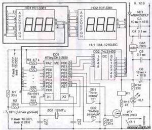
The timer circuit is shown in Fig. 1. The clock frequency of the ATtiny2313 (DD1) microcontroller is set by an external quartz resonator ZQ1. The duration of continuous operation of the pump and the duration of the pause from turning it off to turning it on again are set using two buttons (SB1 and SB2)
These values are stored in the microcontroller's non-volatile memory, so there is no need to reset them after each power cycle, which is especially important in rural areas. When the power is restored, the timer begins its work with a pause, which protects the pump from failure as a result of repeated switching on and off in a short period of time
During the timer operation, two three-digit seven-element LED indicators with common cathodes (HG1, HG2) display the time remaining until the pump turns on (when pausing) or until it turns off (during water supply). Indication is dynamic. The DD2 decoder with outputs made according to the “open collector” circuit converts the three-digit binary code of the familiarity number generated by the microcontroller into signals supplied to the cathodes of the indicators for their turn-on. The pump also stops when the maximum level sensor SF1 is triggered. This is accompanied by the display of the inscription FULL on the indicator. The sensor can be any microswitch equipped with a lever with a float. For greater reliability, you can install another microswitch that breaks the power supply circuit of the timer if the SF1 sensor does not work for any reason.
Rice. 2
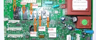
All parts of the device, except for the SF1 sensor, are mounted on a printed circuit board made of fiberglass foil on both sides, shown in Fig. 2. In its original version, unused sections of foil on both sides of the board are connected to the -(9...12) V circuit and serve as an additional common wire. The board is designed for surface-mount parts (except for the quartz resonator ZQ1, stabilizer DA1, indicators HG1, HG2, buttons SB1, SB2 and relay K1). Relay type - JRC-23F. Its coil resistance is 167 Ohms, operating voltage is 5 V. The contacts are designed for switching alternating voltage up to 125 V with a load power of no more than 62.5 VA. A pump or other actuator whose power exceeds the capabilities of this relay can be turned on using another relay or contactor rated for the appropriate current and voltage. Relay K1 in this case will serve as an intermediate one.
Rice. 3
The board also has an XP1 pin connector, the contacts of which are connected to the pins of the microcontroller according to the diagram in Fig. 3. It is designed to connect the programmer to a microcontroller already installed on the board. The table shows how the microcontroller configuration bits should be programmed. They specify its operation with a quartz resonator with a frequency of more than 8 MHz and a program start delay of 16,000 cycles. To protect information in the EEPROM of the microcontroller from accidental damage during the rise of the supply voltage, the response threshold of the internal voltage detector (BODLEVEL) is set to 1.8 V.
When loading codes from the Pump-Control.hex file available in the application into the microcontroller's program memory, the pump operating time and pause duration can be independently changed from 0 to 60 minutes in 1-second increments. The timer consumes a current of no more than 500 mA from a voltage source of 9...12 V.
The timer microcontroller program can be downloaded here
Leave your comment or question:
Electronic equipment directly from the manufacturer
NPO Elektroavtomatika (Cheboksary) is not only a seller, but also a manufacturer of off-on time relays for pumps and stations, as well as many other devices for automating work processes. We have been producing and selling them for more than 10 years, cooperating not only with individuals (who purchase devices for domestic use), but also with large industrial and manufacturing enterprises (which use the equipment on their production lines).
To buy a time relay for automating the operation of pumps and other components directly from the manufacturer, contact us by phone, request a call back, or leave your request on the website. It is worth noting that we can manufacture devices according to individual parameters. If you need a relay with a different operation diagram from the basic one, an increased or decreased range, supply voltage, maximum current or other characteristics, just let us know.
Functions and characteristics of lighting control timers.
The main thing you should pay attention to when purchasing is the maximum permissible switched load.
Which is easy to calculate by simply adding up the power that you plan to connect to the timer. To convert to Amperes, divide the Watts by the operating voltage of 220 Volts. When purchasing, it is very important to pay attention to the type of fastening. which can be placed under the Din rail of the electrical panel, and the timer can also be designed for built-in installation inside a wall or overhead. Third is the operating temperature range
which is important when installing in unheated places.
According to the type of control, they are divided into: mechanical (Figure 1) and more accurate and functional electronic (Figure 2 and 3). There are models of switches with a built-in timer for entrances (Figure 4), which, after pressing, turn on and off after a specified number of seconds. Timers are available to control one channel or two, as well as multi-channel (Figure 3). Two-channel allows you to separately configure and control the main and auxiliary lighting. When purchasing, please note that the timer can only have a weekly or annual program. More expensive models almost always have all kinds of programs, including weekends. Pay attention to the astronomical timer. which allows, after setting the location coordinates, to automatically adjust the time of sunset and dawn taking into account changes in the length of the day during the year.
There are other unimportant characteristics. Such as, for example, time accuracy, minimum time setting (usually up to a minute), etc.
Daily/weekly timer
A device that operates according to a pre-set program. It is used to control processes in automation systems, both in everyday life and in production.
How the timer works
Such a programmable timer allows you to control the load in both daily and weekly modes. You can choose suitable time intervals, as well as an arbitrary number of on and off (a good indicator is at least 200). Modern timers “know what weekends and weekdays are.”
Well, we’ve briefly talked about this device, and now let’s move on to the topic of using it in tandem with an electric boiler to heat a room. The thing is that there are day and night tariffs for the use of electricity by citizens of Ukraine. And the night rate is a reduced rate (from 23:00-7:00). And if your electric boiler is paired with a timer, then you can easily program it for different operating modes during the day, evening and night. For example, if you are not at home during the day (you are at work, children are at school, kindergarten), the timer program will switch your boiler to the minimum you need. And by the time you return home, the other team will switch the boiler to the maximum that suits you. Again, during the night the apartment (house) will have time to heat thoroughly. The logic is clear and understandable, and the saving of your money, so to speak, is obvious. But they can say, and quite rightly, that now there are electric boilers with a built-in timer. Yes, this is true, but... there are different situations.
Situations.
For example, someone already has an electric boiler (without a timer) and the boiler’s service life has not yet expired, and in general, the owner is happy with everything, “if only they could add a timer.” Or, someone who has an electric boiler plans to switch to gas heating over time, but now wants to take advantage of a preferential tariff. Also an option. Also, an electric boiler can perfectly serve as a backup heat source, you never know. All such situations require a device such as a weekly (daily) timer to be solved.
What else can I mention?
Perhaps it would not be amiss to say where else this device can be used. And it can be used in the control of lighting devices, refrigeration units, ventilation equipment, etc., when their work needs to be regulated by time frames (intervals). And, as we said above, this device can also be used in production.
Note.
Good timers have an autonomous power supply to maintain the functionality of the program in case of power failure, as well as automatic transition to summer and winter time. Therefore, if you decide to buy a daily/weekly timer, then you already know what to focus on.
Need advice! What is more correct and better, from the point of view of ease of use, to connect a 4.5 kW electric boiler, according to scheme 1 or 2? Contactor - » > VN - load switch for 32A, IEK. Socket with timer Feron TM50 16A, 3500W.
P.S. Everything - automatic machines, RCDs, etc., are located in the input panel, here we are only talking about connecting the boiler.
I like this one, but I would like it
The first circuit, only instead of VN-32, use AB 1A contactor coil to protect it.
And such a moment. A 16A socket is connected to the 2x4 cable, and therefore the circuit breaker on the 2x4 cable should also be no more than 16A.
VN, because it will be used as a switch, just so as not to pull the plug from the timer every time. But clicking the machine back and forth is not advisable. I’ll probably add an automatic machine in sequence, but on 1A it’s exotic and . price.
Well, basically yes, I didn’t notice, thank you!! What should I do?
Pump control conditions
A simple way to ensure water circulation in the circuit is to install the pump in the gap in the return pipeline and turn it on constantly.
Attention!!! When choosing a pump for circulation in a multi-storey private house, it is necessary to take into account the water pressure that it is capable of creating.
The disadvantage of this method is that the initial savings in two or three years will develop into a constant overpayment of electricity bills. It is much wiser to turn on the circulation only when it is required.
Situations when a running pump is not needed:
- At night everyone sleeps and there is no need for immediate hot water, but, for example, if a person went to the toilet, then it is logical that after that he will go to wash his hands and water is already needed.
- The water in the pipeline is already hot, in this case the operation of the circulation pump is not required.
- You can also turn off the pump if there is no movement in the house for a long time.
These tasks are no longer possible for pumps with standard functions, but it is quite possible to program the Arduino controller to implement this idea.
Another option for reasonable savings is to make the pump work at a certain frequency due to the fact that the water in the pipes does not cool down immediately, but after some time. All this is possible with Arduino.
Timer connection diagram.
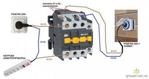
Today, a huge number of different types of timers are sold, which will have their own connection features. I will look at the connection diagram for the popular model of a two-channel timer from the Russian manufacturer IEK.
On top, contacts numbered 1 and 2 are supplied with 220 Volts from the home electrical network. As a rule, in all models, power is supplied from the top, and switching (on and off control) is carried out using the bottom contacts. In this case, only the phase conductor is broken, and the zero goes directly to the electric lamps. On the middle contact 4, a phase from the electrical panel is connected, which will be separately switched with side connections 5 and 3. If you need to switch only one circuit, then contact No. 5 will remain free.
I recommend looking at ours on the topic. containing visual instructions for selecting, connecting and setting up the electronic timer menu!
Good afternoon! This is the question. The house is heated by a 12 kW electric boiler. No one lives in the house now. I want to install a relay so that the boiler turns on at night, the night tariff is cheaper. What is better to install, a single-phase relay and starter or a three-phase relay. If it's not difficult, a diagram by hand. I'm not an electrician myself, but I have the idea.
Anatoly, hello. I won’t draw the diagram, it’s on the Internet
It is better to use such a scheme. If you have 380 volts in your house, then it is better to use a three-phase starter (if this picture is talking about, then you apply voltage, three phases to contacts 1,3 and 5, that is, from above, and from contacts 2,4 and 6 remove and attach to the electric boiler. It is better to take an electronic timer, not a mechanical one, it can be in the form of a socket (this is cheaper) or in the form of a module on a DIN rail (this is several times more expensive, as a rule). Contactor (starter, which is both more convenient and call it) you need to take it with an operating current of 20 amperes or more. It is not necessary to install a thermal relay, it is usually installed on engines, but it is better to install a circuit breaker on the boiler with a nominal value of 20 amperes (this is the nominal value for about 13-13.5 kW).
There is a working diagram for connecting heaters through a magnetic starter with a block of 2 buttons. there is an IEK timer (exactly the same as yours in the picture). how to connect a timer to turn shadows on and off according to time, but so that the button can also be turned on and off? thank you in advance.
Alexey, hello. You need to supply power to pins 1 and 2, this will be the power supply for the timer itself. Next, as per the diagram, instead of light bulbs, you need to turn on your two heating elements, or more precisely, the control coils of the starters. One coil is turned on instead of the left two lamps, and the second coil is turned on instead of the right three lamps. The essence of the timer is that contact four is the control one (changeover), and contacts 3 and 5 are receiving (in one position, for example “on”, again, for example, contact 3 works, and in the other position “off” - contact 5) . Therefore, by setting equal intervals (or the intervals you need), when the timer is turned on, one heating element will work, and when the second one is turned off. Parallel to the timer, install a two-key pass-through switch in exactly the same way. Use the first key to switch power either to the second key or to the timer, and with the second key you control the first or second starter, bypassing the timer.
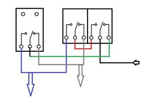
The black arrow is the incoming power, it goes to the first pass-through switch (you will use it to select control, either with the key of the second switch, or with the timer), the second key directly controls the heating elements, if power is supplied to it, and then comes the timer.
https://jelektro.ru
Timer for pump control Meander entertaining electronics
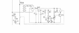
The device, the circuit of which is shown in the figure, periodically generates pulses of positive polarity at the output (at pin 11 of the DD1 microcircuit). It contains two IC generators operating alternately (on elements DD1.1 and DD1.2), a switch on element DD1.3, a serial circuit of four counters of microcircuits DD2, DDЗ, an inverter on element DD1.4 and an electronic relay on transistor VT1 and electromagnetic relay K2, which controls the operation of magnetic starter K1. The duration of the pulses (Ton) and pauses between them (Toff) depends on the frequency of the pulses generated by the pulse generators and the counter outputs used and can be adjusted within wide limits.
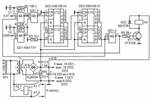
When the device is connected to the network, a constant supply voltage appears at the output of rectifier VD1 and, thanks to circuit R3C3, the counters of microcircuits DD2, DD3 are set to zero. In this case, a log level appears at the output of inverter DD1.4. 1 and the generator on element DD1.2 is switched on. At the same time, transistor VT1 opens, relay K2 is triggered and with its contacts K2.1 it connects the winding of the magnetic starter K1 to the network, as a result of which it also triggers and with contacts K1.1, K1.2 it connects the load to the network. From the output of element DD1.3, pulses with the repetition rate of this generator are supplied to the CN input (pin 2) of the first counter of the DD2 microcircuit. The countdown begins.
With the advent of log. 1 at the counter output (pin 14 DD3) logic level. 1 at the output of element DD1.4 is replaced by a log level. 0, transistor VT1 closes, de-energizing relay K2, it releases and breaks the power circuit of the magnetic starter K1, which, in turn, turns off the load. At the same time, the generator on element DD1.1 is turned on, pulses with the frequency of this generator begin to arrive at the CN input of the first counter of the DD2 microcircuit - the countdown of the Toff time begins, after which everything is repeated from the beginning.
In practice, the device has been used for four years to control, according to a given cycle, a water pump with a capacity of 2500 l/h, pumping water from a well with a flow rate of 300 l/h. For the ratings of the elements R1, R2, C1 and C2 indicated in the diagram, the pump is turned on for a time Ton = 151 s = 2 min 31 s, pumps out about 130 liters of water into the storage tank, and then turns off for a time Toff = 27 min, during which water accumulates in the well. The need to control a pump with such a cycle is due to the fact that without washing with water, the pump fails. The device is powered from an unstabilized source containing a step-down transformer T1 with a secondary winding of 9 V and a rectifier bridge KTs405A. To control the K1 starter, relay K2 is used with a winding resistance of about 700 Ohms and a rated voltage of 12 V.
Time relay for turning on the pump as an integral element of the automation system
Time relayBuy from 1875 rub.
A time relay is a special electrical device that can be used to control the operation of a pump and other electrical equipment. The device is capable of closing/opening electrical circuits. circuit and form time intervals for turning on/off electrical devices. Due to this, a certain sequence (algorithm) of the operation of electrical elements is ensured. scheme. Thus, the relay creates a time delay and automatically controls such technological processes as: irrigation, heating, water supply, air conditioning, etc.
For example, in a heating system with pump circulation, using a relay, it is possible to organize the operation of the pump so that it turns on with a certain time delay, and the heating elements of the electric heating boiler have time to warm up. Thus, the stability and uninterrupted operation of important production and technological processes depends on the reliability of the time relay.
We present to your attention professional devices for automating the operation of an electric pump from the Russian manufacturer NPO Elektroavtomatika - time relays. Electromechanical devices contain several algorithms for working with wide time intervals and supply voltage tolerances, due to which they demonstrate high quality characteristics in each case of operation.
We produce 2 types of relays:
- time relay for shutdown RV-OO for electrical control. circuits after removing the supply voltage;
- time relay for turning on RV-OV for electrical control. circuits after supply voltage is applied.
Let's tell you why a relay is an excellent choice for a water supply system. Using our devices, you can simultaneously control 2 independent electrical circuits - 2 switching groups of contacts. That is, you can connect 2 different devices and supply different power to them. The principle of operation of the functional device is that the relay does not turn on the pump immediately after the supply voltage is applied, but after a certain time.
Types of time relays
Time relay with shutdown delay - RV-OV is widely used to control a pump or pumping station. The device allows you to fill the hydraulic tank automatically, regulating the switching on and off of the pump. Contains two operation diagrams and five time delay ranges: 0.1 s; 1 s; 0.1 m; 1m; 0.1 hour. So, for each operation diagram you can specify one of three time intervals and set a time delay for the relay to operate after power is applied.
Advantages of NPO Elektroavtomatika time relay:
- Reliable technical characteristics.
- Switching heavy loads: with active load - 5 A AC.
- Efficiency. Control of two independent electrical circuits - two switching groups of contacts.
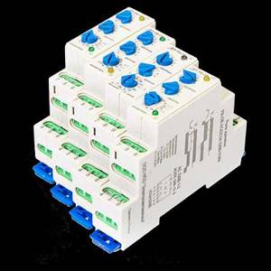
- Easy installation. Installation on a 35 mm wide DIN rail.
The second type of shutdown time relay - RV-OO turns on immediately when the supply voltage is applied, and turns off after a certain time delay after the power is turned off. The device contains four operating diagrams and three time delay ranges: 0.1s; 1s; 0.1 min. In practice, the RV-OO relay allows you to organize an effective automated process control system both in production and in the home.
If you were looking for a reliable device to automate the operation of equipment such as a motor or a pump, and also want to organize a system for turning on and off electrical appliances, then the NPO Elektroavtomatika time relay is suitable for you. For more than 10 years, our devices have remained in demand in automation systems. When ordering, you can specify the required operating diagram, exposure time range, supply voltage and other characteristics.
Buy a time relay to turn on the pump
On our website you can order a functional time relay to turn on the pump. In addition, in our catalog you will find a comprehensive range of electrical products adapted to your requirements: from basic solutions to manufacturing according to the customer’s project and the embodiment of your ideas in the finished product.
We invite you to cooperate with our production company and offer to order reliable electrical products at attractive prices. In NPO Elektroavtomatika you will find a direct supplier and will be able to order the necessary electrical devices and components with delivery to any region of Russia.
Advantages of our devices
Time relays produced by NPO Elektroavtomatika have a number of advantages over both products of many other brands and over other types of relays (motor, pneumatic). Among them:
- durability and reliability;
- possibility of use with heavy loads – up to 5A;
- efficiency. The presence of two groups of switching contacts independent from each other allows you to control two parallel circuits;
- easy to install. Installation of time relays on 35 mm rails does not require special tools or surface preparation;
- high accuracy. The presence of a large number of adjustment ranges (up to 0.1 s) allows for maximum control over the operation of pumps and other devices;
- strength. The device body is resistant to abrasion, scratches, shocks and other mechanical damage.