Calculation of thermal power
1. Determine the thermal power to heat the required volume of air. 1.1 Determine the mass flow of heated air G (kg/h) = L • р L - volumetric amount of heated air, m³/hour; p - air density at average temperature (divide the sum of the air temperature at the inlet and outlet of the air heater by two), kg/m³. 1.2 Determine the heat consumption for heating the air Q (W) = G • c • (t end - t start) G - mass air flow, kg/hour; c is the specific heat capacity of air at average temperature (add the temperature of the incoming and outgoing air and divide by two), J/(kg•°C); t start — air temperature at the inlet to the heat exchanger, °C; tkon is the temperature of the heated air at the outlet of the ventilation heat exchanger, °C.
An example of selection and calculation of a KSk air heater. Step 1
Carry out a thermal calculation and select a suitable KSk heater for heating 16,000 m³/hour from a temperature of -25°C to +23°C. The coolant is hot water with a schedule of 95°C at the inlet to the air heater, 60°C at the outlet. 1. Determine the thermal power required to heat air with a volume of 16,000 m³/hour from a temperature of -25 to +23 degrees. 1.1 Determine the mass flow rate of heated air G (kg/h) = 16000 • 1.30 = 20800 kg/h 16000 - volumetric amount of heated air, m³/hour; 1.30 - air density at a temperature of -1°C (the temperature at the inlet to the heater is -25°C plus the air temperature at the outlet +23°C - divide by two). (-25+23)/2= -2/2= -1. The density of air at a temperature of -1 has a value of 1.30. 1.2 Determine the heat consumption for heating the air Q (W) = (20800/3600) • 1005 • (23 - (-25)) = 278720 W 20800 - mass air flow, kg/hour; 1005—specific heat capacity of air at an average air temperature of -1°C, J/(kg•°C); +23 — temperature of heated air at the outlet of the heat exchanger, °C; -25 — air temperature at the inlet to the heat exchanger, °C.
| Air density depending on temperature | |||||||||||||||
| temperature, °C | -50 | -45 | -40 | -35 | -30 | -25 | -20 | -15 | -10 | -5 | 0 | +5 | +10 | +15 | +20 |
| density, kg/m³ | 1.58 | 1.55 | 1.51 | 1.48 | 1.45 | 1.42 | 1.39 | 1.37 | 1.34 | 1.32 | 1.29 | 1.27 | 1.25 | 1.23 | 1.20 |
| temperature, °C | +25 | +30 | +35 | +40 | +45 | +50 | +55 | +60 | +65 | +70 | +75 | +80 | +85 | +90 | +100 |
| density, kg/m³ | 1.18 | 1.16 | 1.15 | 1.13 | 1.11 | 1.09 | 1.08 | 1.06 | 1.04 | 1.03 | 1.01 | 1.00 | 0.99 | 0.97 | 0.95 |
| Heat capacity of air depending on temperature | |||||||||||||||
| temperature, °C | -50 | -45 | -40 | -35 | -30 | -25 | -20 | -15 | -10 | -5 | 0 | +5 | +10 | +15 | +20 |
| density, kg/m³ | 1013 | 1012 | 1011 | 1010 | 1010 | 1009 | 1008 | 1007 | 1006 | 1005 | 1005 | 1005 | 1005 | 1005 | 1005 |
| temperature, °C | +25 | +30 | +35 | +40 | +45 | +50 | +55 | +60 | +65 | +70 | +75 | +80 | +85 | +90 | +100 |
| density, kg/m³ | 1005 | 1005 | 1005 | 1005 | 1005 | 1005 | 1005 | 1005 | 1006 | 1006 | 1007 | 1007 | 1008 | 1009 | 1009 |
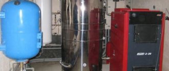
Heating system with air heating unit
A home heating system, based on supplying air heated to a set temperature directly into the house, is of particular interest to homeowners.
This heating system design consists of the following important components:
- a heater acting as a heat generator that heats the air;
- channels (air ducts) through which heated air masses enter the house;
- a fan that directs well-heated air throughout the entire room.
There are many advantages to this type of system. These include high efficiency, the absence of auxiliary elements for heat exchange in the form of radiators, pipes, and the ability to combine it with a climate system, and low inertia, as a result of which large volumes are heated very quickly.
Image gallery
Photo from
Heater - a heating device designed only for processing air flow without changing the humidity of the processed mass
Air heating and air conditioning systems are equipped with air heaters that mix a fresh portion of air from the street to the flow circulating inside
In air heating systems, air heated by a heater is forced into the room using a fan
A significant advantage of using air heaters is their ability to quickly heat large areas and volumes of premises, including workshops, shopping malls, warehouses
Air heating equipment
Air conditioning system with heater
Air heating with heater
Fast heating of large areas
For many homeowners, the disadvantage is that installation of the system is only possible simultaneously with the construction of the house itself and then further modernization is impossible. The downside is such a nuance as the mandatory presence of backup power and the need for regular maintenance.
The heater is easy to install and operate, is affordable, but most importantly, it is an effective device for heating a room. The photo shows a water heater built into the system
Frontal section
2. Selection and calculation of air heaters - stage two. Having determined the required thermal power of the air supply unit’s water heater to heat the required volume, we find the frontal cross-section for air passage. Frontal section is a working internal section with heat-dissipating tubes through which flows of forced cold air directly pass. f (m²) = G / v G - mass air flow, kg/hour; v - mass air velocity - for finned heaters is taken in the range of 3 - 5 (kg/m²•s). Acceptable values are up to 7 - 8 kg/m²•s.
An example of selection and calculation of a KSk air heater. Step-2
Select a suitable KSk supply ventilation air heater for heating 16,000 m³/hour from a temperature of -25°C to +23°C. The coolant is hot water with a schedule of 95°C at the inlet to the air heater, 60°C at the outlet. 2. Calculation of the frontal cross-section for air passage. We select the required cross-sectional area of the KSk heater for a mass air flow of 20800 kg/hour. We take the mass velocity to be 3.6 kg/m²•s. f (m²) = (20800/3600) / 3.6 = 1.605 m² 20800 - mass air flow, kg/hour; 3.6—air mass velocity, kg/m²•s. From the calculation, the required frontal cross-sectional area for air passage was 1.605 m². Next, based on the data from the table below, we select a KSk heater suitable for this section. The most suitable models are KSk 2-11, KSk 3-11 and KSk 4-11 (the frontal cross-sectional area of these heat exchangers is 1,660 m²).
Below is a table with data on two, three and four-row air heaters of the KSk-02-HL3 type manufactured by T.S.T. LLC. The table shows the main technical characteristics for the calculation and selection of all models of these heat exchangers: heating surface area and frontal section, connecting pipes, manifold and free cross-section for water passage, length of heat-heating tubes, number of strokes and rows, weight. Ready-made calculations for various volumes of heated air, incoming air temperature and coolant graphs can be viewed by clicking on the model of the ventilation heater you have chosen from the table.
| Heater name | Area, m² | Heat transfer element length (clear), m | Number of strokes through the internal coolant | Number of rows | Weight, kg | ||||
| heating surfaces | frontal section | collector sections | pipe cross-section | free cross-section (average) for coolant passage | |||||
| KSk 2-1 | 6.7 | 0.197 | 0.00152 | 0.00101 | 0.00056 | 0.530 | 4 | 2 | 22 |
| KSk 2-2 | 8.2 | 0.244 | 0.655 | 25 | |||||
| KSk 2-3 | 9.8 | 0.290 | 0.780 | 28 | |||||
| KSk 2-4 | 11.3 | 0.337 | 0.905 | 31 | |||||
| KSk 2-5 | 14.4 | 0.430 | 1.155 | 36 | |||||
| KSk 2-6 | 9.0 | 0.267 | 0.00076 | 0.530 | 27 | ||||
| KSk 2-7 | 11.1 | 0.329 | 0.655 | 30 | |||||
| KSk 2-8 | 13.2 | 0.392 | 0.780 | 35 | |||||
| KSk 2-9 | 15.3 | 0.455 | 0.905 | 39 | |||||
| KSk 2-10 | 19.5 | 0.581 | 1.155 | 46 | |||||
| KSk 2-11 | 57.1 | 1.660 | 0.00221 | 0.00156 | 1.655 | 120 | |||
| KSk 2-12 | 86.2 | 2.488 | 0.00236 | 174 | |||||
| Heater name | Area, m² | Heat transfer element length (clear), m | Number of strokes through the internal coolant | Number of rows | Weight, kg | ||||
| heating surfaces | frontal section | collector sections | pipe cross-section | free cross-section (average) for coolant passage | |||||
| KSk 3-1 | 10.2 | 0.197 | 0.00164 | 0.00101 | 0.00086 | 0.530 | 4 | 3 | 28 |
| KSk 3-2 | 12.5 | 0.244 | 0.655 | 32 | |||||
| KSk 3-3 | 14.9 | 0.290 | 0.780 | 36 | |||||
| KSk 3-4 | 17.3 | 0.337 | 0.905 | 41 | |||||
| KSk 3-5 | 22.1 | 0.430 | 1.155 | 48 | |||||
| KSk 3-6 | 13.7 | 0.267 | 0.00116 (0.00077) | 0.530 | 4 (6) | 37 | |||
| KSk 3-7 | 16.9 | 0.329 | 0.655 | 43 | |||||
| KSk 3-8 | 20.1 | 0.392 | 0.780 | 49 | |||||
| KSk 3-9 | 23.3 | 0.455 | 0.905 | 54 | |||||
| KSk 3-10 | 29.7 | 0.581 | 1.155 | 65 | |||||
| KSk 3-11 | 86.2 | 1.660 | 0.00221 | 0.00235 | 1.655 | 4 | 163 | ||
| KSk 3-12 | 129.9 | 2.488 | 0.00355 | 242 | |||||
| Heater name | Area, m² | Heat transfer element length (clear), m | Number of strokes through the internal coolant | Number of rows | Weight, kg | ||||
| heating surfaces | frontal section | collector sections | pipe cross-section | free cross-section (average) for coolant passage | |||||
| KSk 4-1 | 13.3 | 0.197 | 0.00224 | 0.00101 | 0.00113 | 0.530 | 4 | 4 | 34 |
| KSk 4-2 | 16.4 | 0.244 | 0.655 | 38 | |||||
| KSk 4-3 | 19.5 | 0.290 | 0.780 | 44 | |||||
| KSk 4-4 | 22.6 | 0.337 | 0.905 | 48 | |||||
| KSk 4-5 | 28.8 | 0.430 | 1.155 | 59 | |||||
| KSk 4-6 | 18.0 | 0.267 | 0.00153 (0.00102) | 0.530 | 4 (6) | 43 | |||
| KSk 4-7 | 22.2 | 0.329 | 0.655 | 51 | |||||
| KSk 4-8 | 26.4 | 0.392 | 0.780 | 59 | |||||
| KSk 4-9 | 30.6 | 0.455 | 0.905 | 65 | |||||
| KSk 4-10 | 39.0 | 0.581 | 1.155 | 79 | |||||
| KSk 4-11 | 114.2 | 1.660 | 0.00221 | 0.00312 | 1.655 | 4 | 206 | ||
| KSk 4-12 | 172.4 | 2.488 | 0.00471 | 307 | |||||
What should we do if, when calculating, we get the required cross-sectional area, but in the table for selecting KSk air heaters, there are no models with this indicator. Then we accept two or more air heaters of the same number so that the sum of their areas corresponds or approaches the desired value. For example, when calculating, we got the required cross-sectional area - 0.926 m². There are no air heaters with this value in the table. We take two KSk 3-9 heat exchangers with an area of 0.455 m² (in total this gives 0.910 m²) and install them in parallel over the air. When choosing a two, three or four row model (same heater numbers - have the same frontal cross-sectional area), we focus on the fact that KSk4 heat exchangers (four rows) at the same incoming air temperature, coolant schedule and air capacity , heat it on average eight to twelve degrees more than KSk3 (three rows of heat-carrying tubes), fifteen to twenty degrees more than KSk2 (two rows of heat-carrying tubes), but have greater aerodynamic drag.
Selecting an electric ventilation heater
Many manufacturers in their air heater catalogs often indicate not only the installed power, but also the air flow, which greatly simplifies the selection of the required unit. The main thing is to ensure that the parameters do not differ from those indicated in the passport. Otherwise, the unit may fail. The design of a high-quality heater necessarily includes specialized electric heating elements, the total area of which is increased due to the specific pressing of the fins.
Many users prefer to use an online calculator to calculate the air heater, where all the nuances are provided. But even in such a situation, you need to be careful, since the power of the component parts may be too high. When the unit has an operating capacity of 4 kW, it can be powered from a regular outlet. If the power of the heater is greater, then it will need a separate cable that will lead directly to the power panel. If the consumer decides to purchase a unit with an indicator of 8 kW, then it will require a 380 V power supply.
Modern air heaters are lightweight and quite compact in size, and they are also completely autonomous. For stable operation of such units it is not at all necessary to have a centralized hot water supply or steam. The only negative is that due to their low power, they are simply impractical to use over large areas. A secondary disadvantage is that they consume a lot of electricity.
Source
Mass air speed
3. Find the actual mass velocity for the selected one or more heaters. v (kg/m²•s) = G / f G - mass air flow, kg/hour; f is the area of the actual frontal section taken into account, m².
An example of selection and calculation of a KSk air heater. Step-3
Select a suitable KSk heater for heating 16,000 m³/hour from a temperature of -25°C to +23°C. The coolant is hot water with a schedule of 95°C at the inlet to the air heater, 60°C at the outlet. 3. The task is to find the actual mass velocity of the heat exchangers that we have selected. We accept KSk air heaters number 11 as the most suitable frontal cross-section for air passage (1,660 m²). Let's calculate all three models: two-row heater KSk 2-11, three-row KSk 3-11 and four-row KSk 4-11. v (kg/m²•s) = (20800/3600) / 1.660 = 3.48 kg/m²•s 20800 - mass air flow, kg/hour; 1.660 is the frontal cross-sectional area of KSk heaters taken into account, m². Since all three models have the same overall dimensions, the mass velocity in the frontal section of each air heater, regardless of the row, will have the same value.
Conclusions and useful video on the topic
What air density to take when calculating is described in this video:
Video about how a heater works in a heating system:
When choosing a specific type of heater, you should proceed from considerations of feasibility and operational characteristics of the house.
For small areas, an electric heater would be a good purchase, but for heating a large house it is better to choose another option. In any case, you can’t do without a preliminary calculation. .
Are you well versed in the issue of choosing and calculating a heater? Perhaps you would like to share useful recommendations for choosing an air heater or point out an error or inaccuracy in the calculations in the material discussed above? Leave your comment under this article - your opinion may be useful to people who are choosing the right heater for their home.
Source
Water consumption for heating
4. We calculate the coolant flow based on the required thermal power to heat a given volume of air. Gw (kg/sec) = Q / ((cw • (t in - t out)) Q - heat consumption for heating air, W; cw - specific heat capacity of water (supply and outlet water temperatures are summed and divided in half), J /(kg•°C); tin - water temperature at the inlet to the heat exchanger, °C; tout - water temperature at the outlet of the heat exchanger, °C.
An example of selection and calculation of a KSk air heater. Step-4
Select a suitable KSk heater for heating 16,000 m³/hour from a temperature of -25°C to +23°C. The coolant is hot water with a schedule of 95°C at the inlet to the air heater, 60°C at the outlet. 4. Calculation of hot water consumption. The coolant consumption is calculated with a temperature chart of 95°C - 60°C for heating 16,000 m³/hour from a temperature of -25°C to +23°C. Gw (kg/sec) = 278720 / ((4196 • (95 - 60)) = 1.898 kg/sec = 6833 kg/hour 278720 - heat consumption for heating air, W; 4196 - specific heat capacity of water at a temperature of 77.5 ° C ( 95°С + 60°С = 155°С / 2 = 77.5°С), J/(kg•°С); 95 — temperature at the inlet to the heat exchanger, °С; 60 — temperature at the outlet of the heat exchanger, °С.
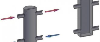
Unique recovery system
Experienced specialists know very well that the direct method of heating the air using the energy of heating devices is not the most practical and economical option for heating with a ventilation system. Heat loss can be significantly reduced using a recovery system with a closed operating cycle.
The operation of this installation is based on excess heat (energy of waste air masses). The diagram of such a unit looks like this: an exhaust and a duct pass through one block, all heat generation from the outgoing air flows is partially transferred to the incoming ones. Thanks to the presence of special heat inflows, the load on other heating systems is reduced.
It is worth noting that installing a heater with recovery is much more expensive than a similar unit, but without this system. Of course, all financial costs quickly pay off, especially in those regions where winter is accompanied by severe frosts.
Coolant speed
5. Calculation of the speed of water movement in the tubes of the adopted heater. W (m/sec) = Gw / (pw • fw) Gw – coolant flow, kg/sec; pw—density of water at average temperature in the air heater, kg/m³; fw is the average open cross-sectional area of one heat exchanger pass (accepted according to the KSk air heater selection table), m².
An example of selection and calculation of a KSk air heater. Step-5
Select and carry out a thermal calculation of the KSk series supply ventilation air heater for heating 16,000 m³/hour from a temperature of -25°C to +23°C. The coolant is hot water with a schedule of 95°C at the inlet to the air heater, 60°C at the outlet. 5. The goal is to calculate the speed of water movement in the tubes of number 11 finned air heaters. W (m/sec) = 1.898 / (973 • 0.00156) = 1.250 m/sec - for heater KSk 2-11 W (m/sec) = 1.898 / (973 • 0.00235) = 0.830 m/sec - for heater KSk 3 -11 W (m/sec) = 1.898 / (973 • 0.00312) = 0.625 m/sec - for heater KSk 4-11 1.898 - coolant flow, kg/sec; 973 - density of water at average temperature in the heat exchanger (graph 95°C-60°C, average 77.5°C), kg/m³; 0.00156 - average open cross-sectional area of one passage of the KSk 2-11 heater, m²; 0.00235 - average open cross-sectional area of one passage of the KSk 3-11 heater, m²; 0.00312 - average open cross-sectional area of one stroke of the KSk 4-11 heater, m². 0.00312 - average open cross-sectional area of one stroke of the KSk 4-11 heater, m².
| Density of water depending on temperature | |||||||||||||||
| temperature, °C | 0 | +5 | +10 | +15 | +20 | +25 | +30 | +35 | +40 | +45 | +50 | +55 | +60 | +65 | +70 |
| density, kg/m³ | 999 | 999 | 999 | 999 | 998 | 997 | 996 | 994 | 992 | 990 | 988 | 986 | 983 | 981 | 978 |
| temperature, °C | +75 | +80 | +85 | +90 | +95 | +100 | +105 | +110 | +115 | +120 | +125 | +130 | +135 | +140 | +150 |
| density, kg/m³ | 975 | 972 | 967 | 965 | 962 | 958 | 955 | 951 | 947 | 943 | 939 | 935 | 930 | 926 | 917 |
| Heat capacity of water depending on temperature | |||||||||||||||
| temperature, °C | 0 | +5 | +10 | +15 | +20 | +25 | +30 | +35 | +40 | +45 | +50 | +55 | +60 | +65 | +70 |
| heat capacity, J/(kg•°C) | 4217 | 4204 | 4193 | 4186 | 4182 | 4181 | 4179 | 4178 | 4179 | 4181 | 4182 | 4183 | 4184 | 4185 | 4190 |
| temperature, °C | +75 | +80 | +85 | +90 | +95 | +100 | +105 | +110 | +115 | +120 | +125 | +130 | +135 | +140 | +150 |
| heat capacity, J/(kg•°C) | 4194 | 4197 | 4203 | 4205 | 4213 | 4216 | 4226 | 4233 | 4237 | 4240 | 4258 | 4270 | 4280 | 4290 | 4310 |
If two or more air heaters are used for calculation, this formula is valid only when they are connected in series along the coolant. That is, the heaters are connected in such a way that hot water, having passed through the contours of one heat exchanger, is supplied to the second, etc. When connecting, for example, two KSk air heaters in parallel for the coolant, the fw value will be 2fw, etc. For example, to heat the air we need two KSk 3-9 heat exchangers with an area of 0.455 m² (in total this gives 0.910 m²). The coolant flow rate was 0.600 kg/sec. Calculate the speed of movement of one stroke of the heaters. With a series connection along the coolant, the formula will look like - W (m/sec) = Gw / (pw • fw), with a parallel connection (the heat pipe is connected to each air heater separately) - W (m/sec) = Gw / (pw • 2fw) . Accordingly, the speed of water movement in the tubes will be greater in the first case than in the second. The recommended speed of coolant movement in water heaters of the KSk type is (0.2 - 0.5) m/sec. Exceeding this speed is associated with an increase in hydraulic resistance. Acceptable values are from 0.12 to 1.2 m/sec.
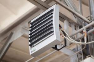
Design of different types of air heaters
A heater is a heat exchanger that transfers the energy of a coolant to an air heating flow and works on the principle of a hair dryer. Its design includes removable side shields and heat-dissipating elements. They can be connected in one or more lines. The built-in fan provides air draft, and the air mass enters the room through the gaps between the elements. When air from the street passes through them, heat is transferred to it. The heater is installed in the ventilation duct, so the device must match the shaft in size and shape.
Water and steam heaters
Types of heat exchangers in heaters
Water and steam heaters can be of two types: finned and smooth-tube. The former, in turn, are divided into two more types: plate and spiral-wound. The design can be single-pass or multi-pass. Multi-pass devices have baffles that change the direction of flow. The tubes are arranged in 1-4 rows.
A heater operating on water consists of a metal, usually rectangular frame, inside of which there are rows of tubes and a fan. The connection is made to the boiler or central heating system using outlet pipes. The fan is located on the inside; it forces air into the heat exchanger. To control power and output air temperature, 2 or 3-way valves are used. The devices are installed on the ceiling or wall.
There are three types of water and steam heaters.
Smooth tube heat exchanger
Smooth tube . The design consists of hollow tubes (diameter from 2 to 3.2 cm), located at small intervals (about 0.5 cm). They can be made of steel, copper, aluminum. The ends of the tubes communicate with the collector. Heated coolant flows into the inlets, and condensate or cooled water comes out of the outlet. Smooth tube models are characterized by lower productivity compared to others.
- minimum inlet temperature – –20°C;
- requirements for air purity - no more than 0.5 mg/m3 in terms of dust content.
Heat transfer coefficient of the heater
6. Calculation of the heat transfer coefficient (thermal efficiency) of the selected supply air heater. The heat transfer coefficient of the selected air heater can be found in two ways. The first is to calculate using the formula (using the coefficients and exponents of a given type of heater). The second is to use a ready-made table with data for different indicators of mass air speed and water speed. Tabular data can be viewed on the website page: KSk heaters. Heat transfer coefficient of heaters KSk.
| Calculation values for calculating heat transfer coefficients | |||||||||||
| KSk2 (2-row model) | A | n | m | KSk3 (3-row model) | A | n | m | KSk4 (4-row model) | A | n | m |
| 33.3 | 0.383 | 0.175 | 29.3 | 0.437 | 0.168 | 25.5 | 0.496 | 0.160 | |||
K W/(m²•°С) = A • Vⁿ • Wᵐ V – actual mass air velocity, kg/m²•s; W is the speed of water movement in the tubes, m/sec; A, n, m - the value of the module and degrees from the table.
An example of selection and calculation of a KSk air heater. Step-6
Select a suitable KSk heater for heating 16,000 m³/hour from a temperature of -25°C to +23°C. The coolant is hot water with a schedule of 95°C at the inlet to the air heater, 60°C at the outlet. 6. The task is to calculate the heat transfer coefficient of KSk air heaters number 11 at a mass velocity in the frontal section of 3.48 kg/m²•s and the corresponding speed of coolant movement in the tubes. K W/(m²•°C) = 33.3 • 3.480.383 • 1.2500.175 = 55.82 W/(m²•°C) - for the KSk air heater 2-11 K W/(m²•°C) = 29.3 • 3.480. 437 • 0.8300.168 = 48.97 W/(m²•°C) - for heater KSk 3-11 K W/(m²•°C) = 25.5 • 3.480.496 • 0.6250.160 = 43.91 W/(m²•°C ) — for air heater KSk 4-11 3.48 — actual mass air velocity, kg/m²•s; 1.250, 0.830, 0.625 - the speed of water movement in the tubes of two, three and four row heaters of the 11th number, respectively, m/sec; 33.3, 0.383, 0.175 (29.3, 0.437, 0.168; 25.5, 0.496, 0.160) - the value of the module and degrees from the table depending on the row of the air heater.
additional literature
- “Use of Id chart for calculations” of the reference book “Internal sanitary installations. Part 3. Ventilation and air conditioning. Book 1." M.: “Stroyizdat”, 1991. Air preparation.
- Ed. I.G. Staroverova, Yu.I. Schiller, N.N. Pavlov and others. “Designer’s Handbook” Ed. 4th, Moscow, Stroyizdat, 1990.
- Ananyev V.A., Balueva L.N., Galperin A.D., Gorodov A.K., Eremin M.Yu., Zvyagintseva S.M., Murashko V.P., Sedykh I.V. “Ventilation and air conditioning systems. Theory and practice." Moscow, Euroclimate, 2000.
- Becker A. (translation from German by Kazantseva L.N., edited by Reznikov G.V.) “Ventilation systems” Moscow, Euroclimate, 2005.
- Burtsev S.I., Tsvetkov Yu.N. "Wet air. Composition and properties. Tutorial." St. Petersburg, 1998
- Flaktwoods technical catalogs
Temperature pressure of the heater
7. Calculation of temperature pressure. Below are formulas for determining the arithmetic mean or logarithmic mean temperature difference (depending on the final temperature delta ratio). If this step causes you difficulties, you can skip it and go to point 8. There is a general formula for finding the actual thermal power of the selected heater, which will allow (in most cases) to select a heat exchanger with an acceptable degree of error.
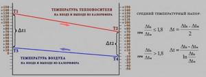
The operating principle of a water heater is based on the heat exchange of two media. The primary coolant is hot or superheated water, the secondary is air. Therefore, this heat exchanger is also called water-air heat exchanger. Heating of the air occurs due to the transfer of heat from the primary coolant (hot water) to the secondary coolant (cold air). That is, we can conditionally divide the heat exchange media into two flows or circuits. The first circuit is the heating side - hot water coolant, the second circuit is the heated side - air coolant. The greater the temperature difference between the flows, the more efficient the heat exchange occurs. The average temperature difference is calculated in the following sequence: Δt1=T1-T3 Δt2=T2-T4 T1 - inlet temperature (hot side); T2—outlet temperature (hot side); T3—outlet temperature (cold side); T4 - inlet temperature (cold side). Δt B - the largest value of the temperature deltas; Δt m is the smaller value of the temperature deltas.
The natural logarithm of ln is the logarithm of base e, where e is an irrational constant equal to approximately 2.71828. The designation is ln(x) exponent to which the number 2.71828 must be raised to get x.
An example of selection and calculation of a KSk air heater. Step-7
Select a suitable KSk heater for heating 16,000 m³/hour from a temperature of -25°C to +23°C. The coolant is hot water with a schedule of 95°C at the inlet to the air heater, 60°C at the outlet. 7. The task is to calculate the average temperature difference with the coolant at the inlet +95°C - at the outlet +60°C, the temperature of the inlet-outlet air -25°C - +23°C. Δt1=95-23=72 Δt2=60-(-25)=85 +95°С — inlet temperature (hot side); +60°С — outlet temperature (hot side); +23°C — outlet temperature (cold side); -25°C — inlet temperature (cold side). Δt B - the largest value of the temperature deltas = 85; Δt m - the smaller value of the temperature deltas = 72.
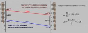
The average temperature pressure for heaters KSk2, KSk3 and KSk4 number 11, heating air from -25°C to +23°C with hot water with a schedule of +95°C-60°C is 78.5°C.
It should also be taken into account that when ΔtB / Δtm > 1.8, the formula is used to find the average logarithmic temperature difference. A detailed description of the calculation using this formula can be found on the website page: Selection of KPSk air heaters.
Definition
A heater (the more professional name is “duct heater”) is a universal device used in internal ventilation systems to transfer thermal energy from heating elements to air passing through a system of hollow tubes.
Duct heaters differ in the way they transfer energy and are divided into:
- Water - energy is transmitted through pipes with hot water and steam.
- Electric - heating elements that receive energy from the central power supply network.
There are also air heaters that operate on the principle of recovery: this is the recovery of heat from the room by transferring it to the supply air. Recovery is carried out without contact of two air environments.
More detailed information about the design and regulatory data of SNiP and GOST is presented in the article “Description of air heaters and supply ventilation piping units.”
Electric heater
The base is a heating element made of wire or spirals, an electric current passes through it. Cold street air is passed between the spirals, it is heated and supplied to the room.
The electric heater is suitable for servicing low-power ventilation systems, since no special calculations are required for its operation, since all the necessary parameters are indicated by the manufacturer.
The main disadvantage of this unit is the inertia between the heating filaments, which leads to constant overheating and, as a consequence, failure of the device. The problem is solved by installing additional compensators.
Water heater
The basis of a water heater is a heating element made of hollow metal tubes, through which hot water or steam is passed.
Outside air comes from the opposite side. Simply put, air moves from top to bottom, and water moves from bottom to top. Thus, oxygen bubbles are removed through special valves. The water duct heater is used in most large and medium-sized ventilation systems. This is facilitated by high productivity, reliability and maintainability of the equipment.
In addition to the heating element, the system includes a piping unit: (provides the supply of coolant to the exchanger), a pump, direct and check valves, shut-off valves and an automatic control unit. For climatic zones where the minimum temperature in winter drops below zero, a system is provided to prevent freezing of the working tubes.
Actual heater power
8. Calculation of the actual thermal power of the selected heater(s) for supply ventilation. q (W) = K • F • ((t in + t out)/2 - (t start + t end)/2)) or, if the temperature difference is calculated, then q (W) = K • F • average temperature pressure K—heat transfer coefficient, W/(m²•°C); F - heating surface area of the selected heater (accepted according to the selection table), m²; tin—water temperature at the inlet to the heat exchanger, °C; tout—water temperature at the outlet of the heat exchanger, °C; t start — air temperature at the inlet to the heat exchanger, °C; t con is the temperature of the heated air at the outlet of the heat exchanger, °C.
An example of selection and calculation of a KSk air heater. Step-8
Select a suitable KSk heater for heating 16,000 m³/hour from a temperature of -25°C to +23°C. The coolant is hot water with a schedule of 95°C at the inlet to the air heater, 60°C at the outlet. 8. Calculation of the actual heating capacity of air heaters KSk number 11, with the specified and calculated values, is carried out using the following formula for calculating the heater power: q (W) = 55.82 • 57.1 • ((95 +60)/2 - (-25 +23) /2)) = 250205 W - for heater KSk 2-11 q (W) = 48.97 • 86.2 • ((95 +60)/2 - (-25 +23)/2)) = 331365 W - for heater KSk 3 -11 q (W) = 43.91 • 114.2 • ((95 +60)/2 - (-25 +23)/2)) = 393640 W - for heater KSk 4-11 55.82, 48.97, 43.91 - heat transfer coefficients of heaters, W/(m²•°C); 57.1, 86.2, 114.2 - heating surface area of air heaters, m²; 95 — water temperature at the inlet to the heat exchanger, °C; 60 — water temperature at the outlet of the heat exchanger, °C; -25 — air temperature at the inlet to the heat exchanger, °C; 23 — temperature of heated air at the outlet of the heat exchanger, °C.
Advantages and disadvantages
Despite all their convenience, heaters consume a large amount of electricity.
Water and steam heaters designed for heating industrial premises are extremely profitable because they do not require additional investments. Financial resources are spent only on the purchase of the device. Their advantages:
- quickly achieving the desired air temperature;
- simple installation;
- safety;
- reliability;
- possibility of adjusting the heating level.
Disadvantages include:
- use in rooms with positive air temperatures;
- impossibility of using for heating apartments;
- equipment is required to provide air traction;
- If the coolant supply stops, the system stops working.
The last point is also true for electric heaters, but only concerns power outages.
Actual water flow and speed
9. Calculate the actual flow and speed of the coolant. 9.1 Calculation of actual hot water consumption. gw (kg/sec) = q / (cw • (t in - t out)) q - actual thermal power of the selected air heaters, W; cw is the specific heat capacity of water (the water temperature at the supply and outlet is summed up and divided in half), J/(kg•°C); tin—water temperature at the inlet to the heat exchanger, °C; tout—water temperature at the outlet of the heat exchanger, °C. 9.2 Calculation of the actual coolant velocity. w (m/sec) = gw / (pw • fw) gw - actual coolant flow, kg/sec; pw—density of water at average temperature in the air heater, kg/m³; fw is the average open cross-sectional area of one pass of the selected heat exchanger, m².
An example of selection and calculation of a KSk air heater. Step-9
Select a suitable KSk heater for heating 16,000 m³/hour from a temperature of -25°C to +23°C. The coolant is hot water with a schedule of 95°C at the inlet to the air heater, 60°C at the outlet. 9. The task is to clarify the actual flow rate and speed of the coolant in the selected heat exchangers. 9.1 Calculation of actual hot water consumption gw (kg/sec) = 250205 / (4196 • (95 - 60)) = 1.704 kg/sec = 6134 kg/hour - for heater KSk 2-11 gw (kg/sec) = 331365 / (4196 • (95 - 60)) = 2.256 kg/sec = 8122 kg/hour - for heater KSk 3-11 gw (kg/sec) = 393640 / (4196 • (95 - 60)) = 2.680 kg/sec = 9648 kg/hour - for heater KSk 4-11 250205, 331365, 393640 - actual thermal power of two, three and four-row models, W; 4196—specific heat capacity of water at an average temperature of 77.5°C, J/(kg•°C); 95 — temperature at the inlet to the heat exchanger KSk, °C; 60 — temperature at the outlet of the heat exchanger, °C. 9.2 Calculation of the actual coolant speed w (m/sec) = 1.704 / (973 • 0.00156) = 1.123 m/sec - for the KSk 2-11 air heater w (m/sec) = 2.256 / (973 • 0.00235) = 0.987 m/sec - for heater KSk 3-11 w (m/sec) = 2.680 / (973 • 0.00312) = 0.883 m/sec - for heater KSk 4-11 1.704, 2.256, 2.680 - actual coolant consumption by heaters, kg/sec; 973 - density of water at average temperature in the heat exchanger, kg/m³; 0.00156, 0.00235, 0.00312 - average open cross-sectional area of one pass of heaters KSk2-11, KSk3-11, KSk4-11, respectively, m².
Adjusting the heating process
There are two ways to adjust the operating mode:
- Quantitative. The adjustment is made by changing the volume of coolant entering the device. With this method, there are sharp temperature changes and instability of the regime, so the second type has recently become more common.
- Qualitative. This method allows you to ensure a constant flow of coolant, which makes the operation of the device more stable and smooth. With a constant flow rate, only the temperature of the medium changes. This is done by mixing some colder return flow into the direct flow, which is regulated by a three-way valve. This system protects the structure from freezing.
Heater power reserve
10. Determine the thermal performance reserve of the adopted heater(s). ((q - Q) / Q) • 100 q - actual thermal power of the selected air heaters, W; Q is the calculated thermal power for heating the required volume of air, W. The actual thermal performance of the adopted ventilation heater must be greater than the calculated one. The range of the permissible percentage ratio of actual and calculated power, according to various sources, can be from 96 to 120 (from - 4 to 20)%. In any case, you need to strive for the closest possible equality of power (actual performance = 100 - 110% of the calculated one). If, during the calculation, the difference is greater than the above figures, a recalculation should be made.
An example of selection and calculation of a KSk air heater. Step-10
Select a suitable KSk heater for heating 16,000 m³/hour from a temperature of -25°C to +23°C. The coolant is hot water with a schedule of 95°C at the inlet to the air heater, 60°C at the outlet. 10. We calculate the discrepancy between the actual and calculated thermal power of the selected heat exchangers ((250205 - 278720) / 278720) • 100 = -10.2% - for the KSk 2-11 air heater ((331365 - 278720) / 278720) • 100 = 18.9% - for heater KSk 3-11 ((393640 - 278720) / 278720) • 100 = 41.2% - for heater KSk 4-11 250205, 331365, 393640 - actual thermal power of selected water heat exchangers, W; 278720 — calculated thermal power for heating a given volume of air, W. Of the considered models of heaters KSk number 11, only the three-row air heater KSk 3-11 corresponds, under given conditions, to the recommended ratio of actual and calculated power.
Heater air resistance
11. Calculation of aerodynamic drag. The amount of air losses can be determined in two ways. The first is to calculate using a formula using the coefficient and degree values of the selected heater. The second is by selection - according to the table, using data at different mass air speeds. View the table with data on the aerodynamic resistance of KSk water heaters.
| Estimated values for calculating aerodynamic drag | ||||||||
| KSk2 (2-row model) | B | r | KSk3 (3-row model) | B | r | KSk4 (4-row model) | B | r |
| 4.23 | 1.832 | 6.05 | 1.832 | 8.63 | 1.833 | |||
ΔPa (Pa) = B • Vʳ V – actual mass air velocity, kg/m²•s; B, r - the value of the module and degrees from the table.
An example of selection and calculation of a KSk air heater. Step-11
Select a suitable KSk heater for heating 16,000 m³/hour from a temperature of -25°C to +23°C. The coolant is hot water with a schedule of 95°C at the inlet to the air heater, 60°C at the outlet. 11. The task is to find out the aerodynamic resistance of the selected air heaters when working under given conditions. ΔPa (Pa) = 4.23 • 3.481.832 = 41.5 Pa - for heater KSk 2-11 ΔPa (Pa) = 6.05 • 3.481.832 = 59.4 Pa - for heater KSk 3-11 ΔPa (Pa) = 8.63 • 3.481.833 = 84.9 Pa - for heater KSk 4-11 3.48 - actual mass air velocity in the frontal section, kg/m²•s; 4.23, 1.832 (6.05, 1.832; 8.63, 1.833) - the value of the module and degree from the table depending on the row of the air heater.
When installing water heaters sequentially along the direction of air movement, we multiply the resulting aerodynamic resistance value by the number of rows of supply ventilation heat exchangers.
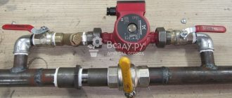
Strapping methods
The piping is a frame made of reinforcement, with the help of which the flow of hot water is regulated. The piping unit helps to monitor the performance of the supply ventilation heater, control it and maintain the desired temperature in the building. The location of the piping units is determined by the installation location, air exchange diagram, and technical parameters of the equipment. There are 2 installation options:
- Recirculated air masses are mixed with supply air.
- Only indoor air is recirculated according to a closed principle.
Taking this into account, there are 2 methods of strapping:
- 2-way valves - with uncontrolled reverse water flow;
- 3-way valves - when controlling water flow in a boiler room or boiler room.
Some produce piping units of various modifications, which are entire sets consisting of valves (balancing and check valves, two and three-way), pumps, bypasses, ball valves, pressure gauges, and cleaning filters.
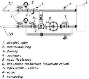
Scheme of piping heater units for supply ventilation. (Ball valves installed at the inlet and outlet allow you to shut off the water, and a thermomanometer allows you to control temperature and pressure)
If natural ventilation is well established, then there are much more opportunities for successful operation of the equipment. The correct choice of piping in such cases is effective both for heating large areas in production and for private houses and cottages.
The heater used for ventilation is usually connected to the heating system directly at the air intake point. If forced ventilation is in effect, the air heater can be installed anywhere. Heaters for supply ventilation allow you to create a comfortable temperature regime in both industrial and residential premises
It is only important to correctly decide on the choice of coolant, which will be the most effective (with minimal costs and maximum performance) under certain conditions. An automated system - such as a supply ventilation control panel with a water heater - will make the use of heating devices for supply ventilation convenient and safe
Water heater resistance
12. Calculation of the hydraulic resistance of the selected heater(s) of the supply ventilation units. Coolant resistance is calculated using formulas. The first requires a fairly large number of actions and is described in detail on the website page: KSk heaters. Hydraulic resistance of heaters KSk. The second is simpler and is solved on the basis of already calculated hydraulic resistance coefficients for specific models of KSk air heaters. The table with odds is presented on the above page. In the same table, focusing on the speed of water in the tubes and the mass speed of air in the frontal section, you can find out the value of water resistance without resorting to calculations. ΔPw (kPa) = C • W² C – the value of the hydraulic resistance coefficient of a given heat exchanger model (see the table); W is the speed of water movement in the tubes of the air heater, m/sec.
An example of selection and calculation of a KSk air heater. Step-12
Select a suitable KSk heater for heating 16,000 m³/hour from a temperature of -25°C to +23°C. The coolant is hot water with a schedule of 95°C at the inlet to the air heater, 60°C at the outlet. 12. The task is to find out the hydraulic resistance of the selected heater when working with the given conditions. ΔPw (kPa) = 21.99 • 1.123² = 27.73 kPa - for heater KSk 2-11 ΔPw (kPa) = 34.25 • 0.987² = 33.37 kPa - for heater KSk 3-11 ΔPw (kPa) = 37.15 • 0.883² = 2 8.97 kPa - for heater KSk 4-11 21.99, 34.25, 37.15 - the value of the hydraulic resistance coefficients for heaters KSk2-11, KSk3-11, KSk4-11 (taken from the table); 1.123, 0.987, 0.883 - speed of water movement in the tubes of the adopted air heaters, m/sec.
If two or more heaters are taken into account for the calculation and they are connected in series through the coolant, the resulting value of hydraulic resistance is multiplied by the number of heat exchangers connected in series through water.
Selection of heater
13. Final indicators of calculation and selection of air heaters KSk 02 HL3 (TU 4863-002-55613706-02) produced by T.S.T. LLC. As a result of the calculation and selection of a heater for heating incoming air from -25°C to 23°C with a volume of 16,000 m³/hour, using a coolant - hot water with a temperature curve of 95°C - 60°C, a finned water heat exchanger KSk 3- was selected 11 three-row, four-way. Data obtained: 1. heater heat power - 331 kW; 2. mass velocity in the frontal section - 3.48 kg/m²•s; 3. coolant consumption - 8122 kg/hour; 4. speed of hot water in the heat exchanger - 0.99 m/sec; 5. thermal power reserve - 19%; 6. aerodynamic resistance - 60 Pa; 7. hydraulic resistance - 33 kPa.
Go to page: Heaters KSk. Production, technical characteristics. The page contains drawings, photographs, descriptions and calculations of these air heaters, tables with thermal characteristics, overall dimensions of water finned heat exchangers of the KSk-02-HL3 type.
a brief description of
In a professional environment, a multifunctional heater is usually called a capital heater. This universal unit is actively used in internal ventilation systems, due to which all thermal energy is transferred from the heating elements to the air, which passes through the hollow tube section.
Absolutely all duct installations differ in the way they transfer heat:
- Electrical. Special heating elements are used that receive energy from the central power supply network.
- Mermen. Timely supply of energy occurs through pipes along with steam and hot water.
On sale you can also find special models of air heaters that operate on a unique recovery principle (a kind of heat recovery from the heated room by transferring it to the supply air). This process occurs without contact of two air environments.
Water apparatus
The main working unit of such heaters is presented in the form of special heating elements, which are made of hollow metal tubes. It is through them that hot steam and water are supplied. External air is captured from the opposite side. In other words, steam moves down and water moves up.
This technology allows air bubbles to be effectively removed through special valves. The multifunctional water duct heater is used in many medium and large ventilation systems. Great demand is due to high productivity, maintainability and reliability of the equipment.
In addition to the heating element, such a heater includes a powerful piping unit, which ensures timely supply of coolant to the main exchanger. This department is equipped with direct and check valves, a pump, a high-quality unit for automated control, and shut-off valves. For those regions of the country where the minimum air temperature in winter drops below zero, manufacturers have provided a special function that prevents the working tubes from freezing.
Electrical installation
The main working unit is a heating element, which consists of spirals or wire. It is this section of the heater that ensures the timely supply of electric current. Cold street air passes between the spirals, which is gradually heated and supplied to the heated room. This electric heater is ideal for servicing low-power ventilation systems. The advantage is that for its operation there is no need to carry out special calculations, since all the necessary parameters are pre-defined by the manufacturer.
It is also worth considering that this unit has one, but quite significant, drawback - there is inertia between the heating filaments, which leads to periodic overheating of the system, which is why it often fails. This problem can be easily eliminated if the unit is equipped with additional compensators.