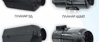
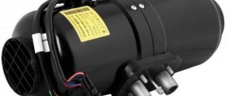
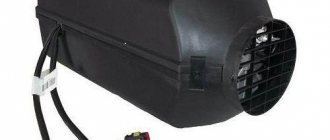
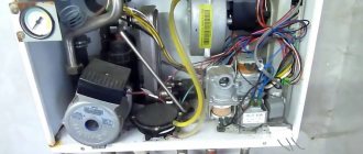
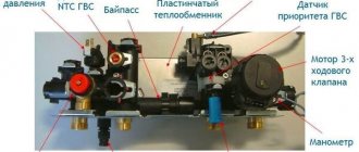
Errors Planar 44D, 44D, 4DM, 4DM2, 2D, 8D, etc.
Below we have collected for you all the error codes for all autonomous heaters of the Planar series. With their help, you can preliminarily determine the breakdown and even fix it on your own, but in some cases you may still have to contact us at the service center for a more accurate diagnosis and save your finances from unnecessary expenses. (If you get the error “candle” or “pump”, do not rush to buy them; first you need to make sure that they are the reason.)
Malfunctions that occur during heater operation are coded and automatically displayed on the control panel indicator. In this case, the fault code and the operating mode LED will flash rarely.
! If you did not find your code in this table, then with a high degree of probability, it is not a code, but the firmware version of the remote control (for digital remote controls). In this case, you need to check the power supply to the heater; the firmware version appears immediately after connecting the power.
| Number of LED flashes | Description of the malfunction | Recommended Troubleshooting Methods | |
| 1 | Heat exchanger overheating | Check the inlet and outlet pipes of the heater for free entry and exit of heated air. Check the overheating sensor on the heat exchanger, replace if necessary | |
| 2 | Startup attempts exhausted | If the permissible number of starting attempts has been used, check the quantity and supply of fuel. Check combustion air supply system and exhaust pipe | |
| 3 | Flame interruption | Check the quantity and supply of fuel. Check the combustion air supply system and the exhaust pipe. If the heater starts, check the flame indicator and replace if necessary. | |
| 4 | Glow plug malfunction | Check glow plug, replace if necessary | |
| 5 | Flame indicator fault | Check the flame indicator circuit for an open circuit; the resistance between the terminals should be no more than 1 ohm. If the indicator is faulty, it must be replaced | |
| 6 | Temperature sensor (on the control unit) | Replace control unit | |
| 7 | Fuel pump malfunction | Check the electrical circuits of the fuel pump for short circuits and open circuits, replace if necessary. | |
| 8 | There is no connection between the control panel and the control unit | Check connecting wires, connectors | |
| 9 | Shutdown, high voltage. Shutdown, undervoltage | Check the battery, voltage regulator and electrical supply wiring. The input voltage should not be higher than 30 V (15 V). Check the battery, voltage regulator and electrical supply wiring. The input voltage must be at least 21.6 V (10.8 V) | |
| 10 | Ventilation time exceeded | During purging, the heater is not cooled sufficiently. Check the combustion air supply system and the exhaust pipe. Check the flame indicator and replace if necessary | |
| 11 | Blower motor malfunction | Check the electrical wiring of the air blower motor, if necessary, replace the air blower | |
| 12 | Overheating inside the heater in the area of the control unit (temperature above 55 degrees) | During the 5-minute purge before starting, the control unit has not cooled sufficiently or the control unit has overheated during operation. It is necessary to check the inlet and outlet pipes of the heater for free air inlet and outlet and repeat the start to cool the heater | |
| 13* | Flame failure in the combustion chamber due to voltage drop | Check the battery and electrical wiring. (Voltage sag may occur due to prolonged use of the electric starter). | |
| 14* | Overheating inside the heater in the area of the heated air outlet temperature sensor | Check the heater inlet and outlet pipes for free air inlet and outlet. | |
| 16* | Heater locked** | To unlock the heater, you must contact a service center. | |
| 0 (78) | A flame failure was recorded during operation. | Shown for user information. Check the tightness of the clamps on the fuel line, the tightness of the fuel line, the tightness of the fitting on the fuel pump | |
* - only for air heaters type PLANAR-8DM
Unlocking Planar-8DM. Reset 33 lock codes.
** Attention! If during startup or operation of the heater the “Overheating” is repeated 3 times in a row, the heater will be blocked.
Blocking is carried out upon overheating, regardless of the sensors that recorded errors. In case of blocking, code 33 will be displayed on the control panel.
To unlock the heater, you must first find out what year it was produced: For the first version of heaters produced (01.2014 - 03.2015), the lock can only be reset using a special program installed on the computer or in our service center.
For the second version of heaters produced (03.2015 – current time), the lock can be reset in two ways: 1) Using a special program. 2) On your own.
Algorithm for resetting the lock WITHOUT using a computer:
■ Connect the product to the power source, start the product, wait for code 33 to appear. ■ After the code appears, within 30 seconds you must disconnect the power connector on the harness or disconnect the power from the heater in any other way. ■ Repeat this procedure 3 times in a row.
If you do not disconnect the power connector within 30 seconds, you will need to start the whole procedure over again. After 3 power resets the heater will be unlocked.
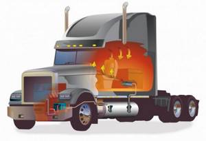
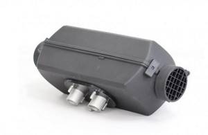
Autonomous "Planar" is an air heater developed by Russian specialists, the production of which is carried out in Samara. The model range of these car heaters consists of four devices (Planar 2D, Planar 4DM2, Planar 44D, Planar 8DM), each of which is available in two versions - 12 and 24 Volts. Even in severe frosts, such an installation can ensure optimal air temperature in the car interior. First, we will briefly consider the design and operating principle of the heater, and then we will study all the “Planar” errors (fault codes) and their interpretation.
Principle of operation
Heaters from this manufacturer operate on the principle of supplying outside air to the heating compartment. When fuel is burned, energy is released that heats the air. Only after this is hot air supplied to the vehicle interior.
To select the optimal power, a special regulator is used with the ability to be fixed in a given position. After the user selects the optimal operating mode, the heater will independently maintain the set temperature.
The basic operating principle of the Planar autonomous vehicle:
- Purge the combustion chamber.
- Heating the glow plugs to the required temperature.
- Supplying the optimal ratio of air and fuel to the working chamber.
- Combustion of the air-fuel mixture.
- Switching off the candle after stabilization of the user-selected temperature mode.
Fault codes Planar 2D-12-S / 2D-24-S
| Code | Malfunction | Reason for error |
| 01 | Increased heat exchanger temperature. | The temperature sensor sends a signal to turn off the autonomy. The heat exchanger in the area where the sensor is installed has reached a temperature of over 250ºС. |
| 02 | Possibility of overheating based on temperature sensor. Its temperature exceeds 55°. | Before starting, during purging for 5 minutes there is not enough cooling or the control unit overheats during operation. |
| 05 | Sensor error. | A break in the electrical wiring or a short circuit to ground (housing). |
| 06 | Error in temperature sensor in control unit. | Failure of the temperature sensor (located in the control unit, replacement is not possible). |
| 09 | Glow plug problems. | Broken or short circuited wiring, failure of the control unit. |
| 10 | The electric blower motor does not reach the required speed. | Electric motor failure. Lack of lubrication in the bearings or contact of the impeller with the volute in the supercharger. |
| 12 | Shutdown, voltage exceeds 16 V (above 30 V for 24 V device). | Failure of the battery or voltage regulator. |
| 15 | Shutdown, voltage below 10V (below 20V for 24V device). | Failure of the battery or voltage regulator. |
| 13 | The device does not start after two attempts. | There is no fuel in the tank. |
The quality of the fuel does not meet the conditions of use in cold weather.
The air intake or exhaust pipe is dirty.
Poor heating of the glow plug, failure of the control unit.
The impeller is in contact with the volute in the air blower, due to which insufficient air is supplied.
Contamination of the hole in the combustion chamber (diameter - 2.8 mm). Contamination of the spark plug grid or incorrect installation in the fitting (not all the way).
There is no connection between the control unit and the remote control. The remote control does not receive information from the unit.
DOCUMENTATION FOR AUXILIARY DEVICES
- Instructions for the Adapter for heaters and heaters479.09 Kb (Added 01/18/2016)
- RS232776.99 KB adapter diagram (Added 02/18/2011)
- Description of the stand for auto centers1.59 MB (Added 01/18/2016)
- Instructions for the swap device507.28 Kb (Added 01/18/2016)
- Instructions for Diagnostic Device 14TS-10, 14TS-20, 14TS-10MK, 11TS428.28 Kb (Added 01/18/2016)
- Instructions for the USB Adapter for heaters and heaters916.46 Kb (Added 06/03/2013)
- Instructions for Remote Timer for 14TS-10, 11TS (Not currently available) 318.93 Kb (Added 01/18/2016)
Errors Planar 4DM2-12-S / 4DM2-24-S
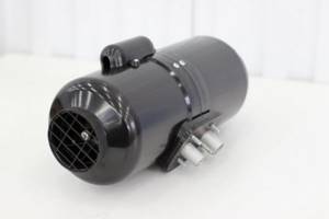
| Code | Number of LED flickers | Problem | Reason for error |
| 13 | 2 | The device does not start after two attempts. | There is no fuel in the tank. |
The quality of the fuel does not meet the conditions of use in cold weather.
The air intake or exhaust pipe is dirty.
Poor heating of the glow plug, failure of the control unit.
The impeller is in contact with the volute in the air blower, due to which insufficient air is supplied.
Contamination of the hole in the combustion chamber (diameter - 2.8 mm). Contamination of the spark plug grid or incorrect installation in the fitting (not all the way).
Autonomy errors Planar 44D-12-GP-S / 44D-24-GP-S
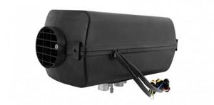
| Code | Malfunction | Reason for error |
| 01 | Exceeding the permissible heat exchanger temperature. | The temperature sensor sends a signal to turn off the autonomy. The heat exchanger in the area where the sensor is installed has reached a temperature of over 250ºС. |
| 02 | Possibility of overheating. Overheating near the control unit in the heater itself. | During purging, there is not enough cooling or the control unit overheats during operation. |
| 04 (06) | Error in temperature sensor in control unit. | Failure of the temperature sensor (located in the control unit, replacement is not possible). |
| 05 | Flame indicator is broken. | A break in the electrical wiring or a short circuit to ground (housing) of the indicator. |
| 08 (29) | The flame breaks out during operation. | Leaks in the fuel supply line, failure (wear) of the fuel pump or flame indicator. Contamination of the air supply or gas exhaust pipes. |
| 09 | Glow plug problems. | Broken or short circuited wiring, failure of the control unit. |
| 10 | The electric blower motor does not reach the required speed. | Electric motor failure. Lack of lubrication in the bearings or contact of the impeller with the volute in the supercharger. |
| 12 | Shutdown, voltage exceeds 16 V (above 30 V for 24 V device). | Failure of the battery or voltage regulator. |
| 15 | Shutdown, voltage below 10V (below 20V for 24V device). | Failure of the battery or voltage regulator. |
| 13 | The device does not start after two attempts. | There is no fuel in the tank. |
The quality of the fuel does not meet the conditions of use in cold weather.
The air intake or exhaust pipe is dirty.
Poor heating of the glow plug, failure of the control unit.
The impeller is in contact with the volute in the air blower, due to which insufficient air is supplied.
Contamination of the hole in the combustion chamber (diameter - 2.8 mm). Contamination of the spark plug grid or incorrect installation in the fitting (not all the way).
Oxidation or corrosion of contacts in the block.
Leaks in the fuel supply line, failure (wear) of the fuel pump or flame indicator. Contamination of the air supply or gas exhaust pipes.
* The new error code is indicated in parentheses.
Error codes Planar-8DM-12-S / 8DM-24-S
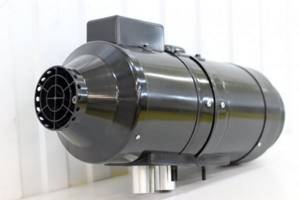
| Code | Description | Cause of malfunction |
| 01 (1) | Exceeding the permissible heat exchanger temperature. | The temperature sensor sends a signal to turn off the device. The heat exchanger in the sensor installation area has reached a temperature of over 250ºС. |
| 02 (12) | Possibility of overheating. Overheating near the control unit in the heater itself. | During purging, there is not enough cooling or the control unit overheats during operation. |
| 04 (06, 6) | Error in temperature sensor in control unit. | Failure of the temperature sensor (located in the control unit, replacement is not possible). |
| 05 (5) | Flame indicator is broken. | A break in the electrical wiring or a short circuit to ground (housing) of the indicator. |
| 7 (17) | Break in the wiring of the overheating sensor. | Failure of the sensor itself. Oxidized contacts in the block. |
| 08 (29, 3) | The flame breaks out during operation. | Leaks in the fuel supply line, failure (wear) of the fuel pump or flame indicator. Contamination of the air supply or gas exhaust pipes. |
| 09 (4) | Glow plug problems. | Broken or short circuited wiring, failure of the control unit. |
| 10 (11) | The electric blower motor does not reach the required speed. | Electric motor failure. Lack of lubrication in the bearings or contact of the impeller with the volute in the supercharger. |
| 11 (18) | Damage to the heated air temperature sensor (supply) | Mechanical defect. Oxidized contacts in the block. |
| 12 (9) | Shutdown, voltage exceeds 16 V (above 30 V for 24 V device). | Failure of the battery or voltage regulator. |
| 15 (9) | Shutdown, voltage below 10V (below 20V for 24V device). | Failure of the battery or voltage regulator. |
| 16 (10) | Ventilation is too long. | During purging, the heater temperature did not drop to the required value. |
| 17 (7) | Fuel pump error. | Open or short circuit in the electrical circuit of the fuel pump. |
| 13 (2) | The device does not start after two attempts. | There is no fuel in the tank. |
Timer-thermostat Pramotronic (15.8106, 151.8106, 141.8106)
| Code | Timer indication | Indication on the warning lamp | Malfunction |
| 1 | E-01 | 1 flash | Failure to start the heater. |
| 2 | E-02 | 2 flashes | No flame ignition. |
| 3 | E-03 | 3 flashes | The supply voltage is below normal. |
| 4 | E-04 | 4 flashes | Flame indicator circuit malfunction. |
| 5 | E-05 | 5 flashes | Malfunction of the high voltage power supply circuit. |
| 6 | E-06 | 6 flashes | Temperature sensor defective. |
| 7 | E-07 | 7 flashes | Solenoid valve circuit malfunction. |
| 8 | E-08 | 8 flashes | Heater fan motor circuit malfunction. |
| 9 | E-09 | 9 flashes | Electric pump circuit malfunction. |
| 10 | E-10 | 10 flashes | The supply voltage is higher than normal. |
| 11 | E-20 | Lack of communication between the control unit and the timer-thermostat. |
Summary
Planar car heaters are a good choice for those who need to provide additional heating for the cabin or covered body of trucks or passenger cars. Please note that to achieve the required results, correct installation of the battery and timely maintenance of the device are extremely important. The price of heaters starts from 19.5 thousand rubles.
This section contains a complete list of error codes for “samarka autonomous cars” Planar Teplostar
A malfunction may occur during operation of the heater. The malfunction is determined by the number of blinks of the LED on the control panel or by the displayed code on the digital remote control. The number of LED blinks, the reasons that led to the failure, and methods for troubleshooting are indicated in the table.
How to determine if a stand-alone oven is faulty
1) Check the fuel level and quality. 1) Visually assess damage to wires, hoses, presence of parts (pump, fuel tank), etc. 3) Calculate error codes for models without a display 4) Carry out repairs according to the documentation
A malfunction may occur during operation of the heater. The malfunction is determined by the number of blinks of the LED on the control panel or by the displayed code on the digital remote control. The number of LED blinks, the reasons that led to the failure, and methods for troubleshooting are indicated in the table.
There may be other malfunctions that are not diagnosed by the control unit, for example: loss of tightness of the heat exchanger (burnout), or burnout of sealing gaskets, or a decrease in thermal performance as a result of carbon formation on the inner surface of the heat exchanger. The listed faults can be detected visually.
Select your model
- 2D-24(2Д-24) 2kW
- 4DM2-24(4DM) 3kW
- 44D-24(44D-12) 4kW
- 8DM-24(8DM) 7-8kW
- Binar 5C
- Binar 5S
- 14TS-10 (14TC, Mini) Kamaz MAZ
If you can’t figure it out at all, we can help with repairs.
| 16 | The sensor temperature did not decrease during purge. | During the 5-minute purge process before starting work, the temperature sensor is not cooled to the required value. | |
| 17 | Fuel pump error. | Open or short circuit in the electrical circuit of the fuel pump. | |
| 20 | The device does not start. | Failure of fuses in the power circuit. | |
| 27 | The motor does not turn. | Jamming as a result of destruction of the rotor, bearing, or the ingress of various objects. | |
| 28 | The engine rotation speed does not change, it does not respond to control commands. | Failure of the electrical motor control board or control unit. | |
| 29 | The flame is interrupted while the device is operating. | Leaks in the fuel supply line, failure of the fuel pump or flame indicator. | |
| 30 | The device does not start. | There is no connection between the control unit and the remote control. The unit does not receive information from the remote control. | |
| 78 | A flame failure was detected during heater operation. | Airing of the fuel supply system, failure of the fuel pump or flame indicator. | |
| 20 | The device does not start. | There is no connection between the remote control and the control unit. | |
| 01 | 1 | Exceeding the permissible temperature. | The temperature sensor sends a signal to turn off the autonomy. The heat exchanger in the area where the sensor is installed has reached a temperature of over 250ºС. |
| 08 | 3 | The flame breaks out during operation. | Leaks in the fuel supply line, failure of the fuel pump or flame indicator. |
| 09 | 4 | Glow plug problems. | Broken or short circuited wiring, failure of the control unit. |
| 05 | 5 | Flame indicator is broken. | A break in the electrical wiring or a short circuit to ground (housing) of the indicator. |
| 04 | 6 | Error in temperature sensor in control unit. | Failure of the temperature sensor (located in the control unit, replacement is not possible). |
| 17 | 7 | Fuel pump error. | Open or short circuit in the electrical circuit of the fuel pump. |
| 12 | 9 | Shutdown, voltage exceeds 16 V (above 30 V for 24 V device). | Failure of the battery or voltage regulator. |
| 15 | 9 | Shutdown, voltage below 10V (below 20V for 24V device). | Failure of the battery or voltage regulator. |
| 10 | 11 | The electric blower motor does not reach the required speed. | Electric motor failure. Lack of lubrication in the bearings or contact of the impeller with the volute in the supercharger. |
| 16 | 10 | Ventilation is too weak to reduce the temperature of the heat exchanger and combustion chamber of the device. | During the purging process before starting work, the flame indicator is not cooled to the required value. |
| 27 | 11 | The motor does not turn. | Jamming as a result of destruction of the rotor, bearing, or the ingress of various objects. |
| 28 | 11 | The engine rotation speed does not change, it does not respond to control commands. | Failure of the electrical motor control board or control unit. |
| 02 | 12 | Possibility of overheating based on temperature sensor. Its temperature exceeds 55°. | Before starting, during purging for 5 minutes there is not enough cooling or the control unit overheats during operation. |
| 17 | Fuel pump error. | Open or short circuit in the electrical circuit of the fuel pump. | |
| 20 | There is no connection between the control unit and the remote control. | Failure of fuses in the power circuit. The remote control does not receive information from the control unit. | |
| 27 | The motor does not turn. | Jamming as a result of destruction of the rotor, bearing, or the ingress of various objects. | |
| 28 | The engine rotation speed does not change, it does not respond to control commands. | Failure of the electrical motor control board or control unit. | |
| 29 | The flame breaks out during operation. | Leaks in the fuel supply line, failure (wear) of the fuel pump or flame indicator. Contamination of the air supply or gas exhaust pipes. | |
| 30 | There is no connection between the control panel and the unit. | The unit does not receive information from the control panel. | |
| 78 | A flame failure was detected during heater operation. | Airing of the fuel supply system, failure of the fuel pump or flame indicator. | |
| 20 (8) | There is no connection between the control panel and the unit. | Failure of fuses in the power circuit. The remote control does not receive information from the control unit. | |
| 27 (11) | The motor does not turn. | Jamming as a result of destruction of the rotor, bearing, or the ingress of various objects. | |
| 28 (11) | The motor rotation speed does not change, it does not respond to control commands. | Failure of the electrical motor control board or control unit. | |
| 29 | The flame breaks out during operation. | Leaks in the fuel supply line, failure (wear) of the fuel pump or flame indicator. Contamination of the air supply or gas exhaust pipes. | |
| 30 (8) | There is no connection between the control panel and the unit. | The unit does not receive information from the control panel. | |
| 31 (14) | The hot air outlet temperature is too high. | The temperature sensor in the air outlet area sends a command to turn off the device. | |
| 32 (15) | Damage to the heated air temperature sensor | Failure of the temperature sensor (outlet). | |
| 33 (16) | Blocking the device. | The error of exceeding the permissible temperature is repeated three times. | |
| 34 (19) | Tampering with the design of the device. | One of the temperature sensors (inlet, outlet or over-temperature) is installed incorrectly and displays unreliable data. | |
| 35 (13) | Flame failure detected. | Supply voltage drop. | |
| 36 (20) | Flame indicator overheating. | Failure of the indicator or breakdown of the stabilizer installed in the combustion chamber of the heater. | |
| 78 (0) | A flame failure was detected during heater operation. | Leaks in the fuel supply line, failure (wear) of the fuel pump or flame indicator. Contamination of the air supply or gas exhaust pipes. |
OPERATING GUIDELINES
- Operating manual for air heater PLANAR-2D-12/242.31 MB (Added 10/23/2014)
- Operating manual Planar-4D884.91 Kb (Added 04/27/2016)
- Operating manual Planar-4DM1.85 MB (Added 04/27/2016)
- Operating manual PLANAR-4DM2 2.78 MB (Added 04/27/2016)
- Operating manual Planar-4DM2 1.92 MB (Added 04/27/2016)
- Operating manual for air heater PLANAR-44D-12/242.76 MB (Added 09.18.2014)
- Operating manual Planar-44D-12/241.49 MB (Added 04/27/2016)
- RE for PLANAR 44-GP RUS-ENG2.76 MB (Added 02/05/2016)
- Operating manual Planar-8DM1.22 MB (Added 04/27/2016)
- Operating manual for air heater PLANAR-8DM-12/242.82 MB (Added 04/27/2016)
- Operating manual Binar-5-Compact (products manufactured before 2013) 1.31 MB (Added 06/03/2013)
- Operating manual Binar-5-Compact2.97 MB (Added 04/27/2016)
- Operating manual Binar-5-Compact-GP3.44 MB (Added 04/27/2016)
- Operating manual Binar-5D-Compact-243.45 MB (Added 04/27/2016)
- Operating manual BINAR 5S369.57 Kb (Added 04/18/2016)
- Installation instructions BINAR 5S1.25 MB (Added 04/18/2016)
- Operating manual Remote control PU-20 BINAR 5S1.05 MB (Added 12/16/2016)
- RE for Binar-5B-5D-Compact-12-GP RUS-ENG3.37 MB (Added 02.02.2016)
- Installation instructions for fuel pump harness BINAR 5S183.06 Kb (Added 04/18/2016)
- Operating manual Teplostar 14TS-10 (KAMAZ) 775.31 Kb (Added 05/19/2011)
- Operating manual 14TS-10 (with installation kit)3.31 MB (Added 04/27/2016)
- Operating manual 14TS-10-24/12-S (with installation kit)2.1 MB (Added 04/27/2016)
- Operating manual Teplostar 14TS-10(BAW)574.75 Kb (Added 11/21/2011)
- Operating manual Teplostar 14TS-10(MAZ)500.25 Kb (Added 06/03/2013)
- Operating manual Teplostar 14TS-10-M5 24V (MAZ)499.75 Kb (Added 06/03/2013)
- Operating manual Teplostar 14TS (URAL) 486.09 Kb (Added 06/03/2013)
- Operating manual Teplostar 11TS (KAMAZ) 798.91 Kb (Added 06/03/2013)
- Operating manual 14TS-10 mini2.6 MB (Added 12/08/2015)
- Operating manual 20TS1.13 MB (Added 04/27/2016)
- Operating manual 20TS-D38899.79 Kb (Added 04/27/2016)
- Operating manual APZh 30D-24908.62 Kb (Added 10/23/2014)
- Operating manual Termmix-15D345.79 Kb (Added 09/15/2011)
- Operating manual GSM Termo v.2590.58 Kb (Added 10/21/2015)
- Operating manual GSM Termo v.3581.76 Kb (Added 10/21/2015)
- Operating manual for modem CINTERION MAKET v6851.93 Kb (Added 12/08/2015)
- Operating manual Remote control PU-11 (additional option) 503.5 Kb (Added 04/03/2012)
- Operating manual for modem SIMCOM794.95 Kb (Added 10/06/2016)
- Operating manual SIMCOM modem 2640.69 KB (Added 12/16/2016)
