In recent years, the installation of heated floors has been successfully combined with a heating system with radiators that are familiar to many. The joint functioning of two such similar and at the same time fundamentally different structures is impossible without a mixing unit for a heated floor.
Since floor heating is a low-temperature system, and heating radiators are a high-temperature system, an indispensable condition for their joint operation is the presence of a mixing unit. Its main functional purpose, as the name suggests, is to mix.
Why might a valve leak?
The pressure relief valve in the heating system can leak for various reasons. In some situations, this is an acceptable natural process; in other cases, a leak indicates a malfunction of the device.
Leakage of the protection valve can be caused by the following reasons:
- Damage to the sealed rubber cup or disc as a result of repeated use. If during repairs a replacement part cannot be found on sale or is not included in the package, you will have to replace the device completely.
- In spring types, the opening of the side drain pipe occurs gradually; at borderline pressure values or short-term surges, the valve may partially operate and drip, which does not indicate its malfunction.
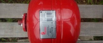
- Leakage can be caused by incorrect settings or malfunctions of the expansion tank - damage to its membrane, air escaping through a depressurized housing or a damaged nipple. In this case, sharp pressure surges are possible as a result of water hammer, causing periodic short-term leakage of coolant through the safety valve.
- The cause of leakage in some adjustable valves is fluid seeping down the stem through the top during actuation.
- If a back pressure is created at the outlet pipe above the device's response threshold, a leak will also occur.
The safety valve of steam boilers is designed to protect them from excess pressure in the system caused by various factors, and is a mandatory element when operating this type of equipment. There is a wide range of safety devices on sale from Chinese, domestic and European manufacturers, which are characterized by a relatively low cost. When purchasing, it is rational to choose a protective group from several devices, which additionally includes a pressure gauge and an air release valve.
Variety of models
Modern production facilities are engaged in the serial production of three-way valves of various types. The final classification of units is carried out taking into account the type of fastening available. Experts are sure to study even the most minor design differences so that the final buyer can purchase the most suitable model.
Tension type unit
These products are in great demand. The tension three-way plug valve for the pressure gauge is characterized by high-quality sealing of all seams and joints. Today there are four most common types of such units:
- A device equipped with a hole with a pipe thread on one side, and a metric element on the other. It is worth noting that the third outlet must be adapted for drainage.
- A product equipped with threads on both sides of a small hole. Manufacturers have provided a special flange for coupling with the measuring unit.
- A universal model in which the through hole has a metric or pipe thread. The developers have provided a third outlet for drainage of the system.
- The high-quality modification of two standard models deserves special attention. A regular handle is designed to open/close the main line (this element can be represented by either a regular lever or a butterfly).
Such parts are made on the basis of brass, which at all times can boast of its ductility and lightness. But finished products have two significant drawbacks:
- Since brass alloy has minimal strength, there is a high risk of the plug tail breaking as a result of over-tightening or inaccurate tightening of the nut.
- The valve needs to generate a lot of force to start the switching mechanism.
High quality products
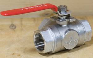
A ball unit with drainage is in great demand in all cases where there is a need to install a trouble-free and reliable three-way valve for a pressure gauge. The main advantages include:
- good tightness;
- convenient and simple design;
- ease of operation;
- compactness;
- ease of installation;
- even after several years, debris does not accumulate in flow zones;
- units of this category can be safely installed in stagnant and viscous units.
It is worth noting that small balls are hidden in the internal compartment of the three-way ball valve, which necessarily have a slot in the form of a large letter “T” or “G”.
Less popular mechanisms
In the first case, powerful mechanisms are presented that can boast a big difference from all products existing today - the universal structure of the tap completely eliminates the possibility of continuous exposure to high pressure on the pressure gauge. All necessary parameters are measured according to the following scheme: a special button is pressed and pressure is applied to the measuring device to record all the necessary data.
A traditional ball valve cannot be described as a three-way model, but despite this, the unit can be used to perform standard functions. Manufacturers use affordable brass, which is necessarily coated with a protective layer of chromium. If necessary, drainage or a control pressure gauge can be connected to the coupling outlet for high-quality data measurement.
Possible breakdowns of Baxi boilers
Repair work on baxi boilers should be done with your own hands only if there are visible and easily removable causes of the breakdown. If you have no experience in handling the units or do not have special tools, it is better to entrust boiler repairs to a competent technician.
- — the boiler burner does not turn on or goes out;
- — ignition becomes impossible;
- — popping sounds are heard in the combustion chamber;
- — the boiler overheats;
- — the maximum heating temperature of the coolant becomes insufficient;
- — the boiler operation becomes noisy;
- — one of the sensors or elements of the system fails.
Causes of failure of baxi boilers:
- — moisture has entered the boiler;
- — water (coolant) of low quality;
- — there has been a drop or decrease in gas pressure in the gas pipeline;
- — there was a power supply voltage drop;
- — the heating system was installed incorrectly.
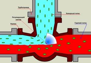
Principle of operation
The coolant - hot water - is connected to one inlet pipe of the device, and the so-called return pipe - the coolant water that has passed through the system and cooled down - is connected to the other pipe.
When the shutter is fully open, a hot stream is supplied to the system.
When the tap is closed, the path to the hot medium is blocked, and return flows into the pipeline.
When the device is not completely closed, the flows are mixed and the heating temperature in the system is adjusted to a certain extent.
Brief introduction to the three-way valve mechanism
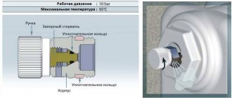
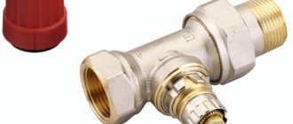
The design of a three-way valve for a domestic gas boiler and other gas equipment is quite simple, despite its complex, at first glance, shape. It should be noted that the design of the valves differs significantly for each manufacturer, but the principle of operation actually remains unchanged.
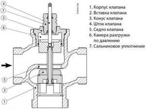
Traditionally, the body of the device is made of bronze. Working elements, for example, a rod, springs, are made of steel. The diaphragm is usually made of rubber. A double ring element is used to seal the rod. Connecting parts (fittings) can be threaded or soldered, depending on the model of the three-way valve.
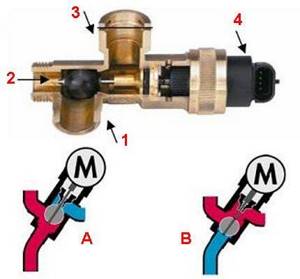
One of the widely used versions of a three-way valve: 1, 2 – angular passage transport channel; 1, 3 – direct through transport channel; 4 – drive head; A – transport of flows in heating mode; B – transport of flows in DHW mode
Typically, an electromechanical drive is used in conjunction with the device. Thanks to its operation, two-point regulation is carried out.
Thus, the drive of a three-way valve can be manual, electromechanical (thermostatic, with a thermal head), electric, or hydraulic.
The operating principle of a three-way valve for a gas boiler circuit is approximately the following: when the device is in the normally open transport mode, the direct through transport channel is, accordingly, open. The corner passage channel remains closed.
A different state of the mechanism ensures the opening of the angular transport channel and blocking of the direct transport channel, respectively. Intermediate positions of the three-way valve stem and flap are also possible.
We talked in more detail about the design and operating principle of a three-way valve in the following material.
The difference between a three-way tap and a gate valve, valve and valve
The faucet, gate valve, valve and thermal valve belong to the class of shut-off and control valves. However, the shape of the bolt mechanism and the principle of operation are different. For greater clarity, I have summarized the comparative characteristics of the devices in a table:
| Tap | Valve | Gate valve | Valve | |
| Shutter function | + | + | + | + |
| Adjustment function | Not recommended | + | + | + |
| Gate shape | Ball, plug | Wedge | Disc, wedge | Books |
| The principle of movement of the bolt mechanism | Around its own axis | Parallel to the flow | Perpendicular to flow | Parallel to the flow |
| Control handle | Lever arm | Flywheel | Flywheel | Lever, flywheel |
| Possibility of installing an electric drive | + | + | + | + |
| Possibility of installing a thermostat | External only (for automatic models) | + | — | + |
| Compactness | + | — | — | + |
From the table data it is clear that the tap is less functional. However, this is precisely why it is more reliable and lasts much longer than its counterparts.
Operating principle and types of valve actuators
The product is produced in different configurations and with different drives, but the principle of operation of the three-way valve remains unchanged: mix two flows with different temperatures into one, the temperature of which is specified by the user or required by the scheme. The liquid inside the valve flows from one pipe to another until its temperature changes and reaches the set value. Then the drive gradually opens the flow from the third pipe, keeping the temperature of the leaving water within the set value. On this basis, such a valve is called a three-way valve.
Operating principle of three-way valve
Any three-way mixing valve has two inlets and one outlet. Flow distribution is carried out using a drive, which comes in several types:
- The thermostatic drive (thermostat) is one of the most popular; it works due to the thermal expansion of the sensing element, as a result of which pressure is placed on the valve stem and the liquid begins to mix.
- A widely used type of drive that is installed in a three-way changeover valve is electric, operating from a signal from the control unit.
- The valve can be controlled by pressing the stem using a thermostatic head drive. It reacts to the air temperature, which it determines itself or using a remote sensor and a capillary tube. The drive is most often used in underfloor heating systems.
Stationary solid fuel boilers cannot be directly included in the heating system. One of the reasons is to prevent cold water from entering the boiler jacket until it has warmed up. Otherwise, condensation is released on the walls of the firebox, which, mixing with ash, forms a durable layer of soot. It interferes with free heat exchange, reducing the efficiency of the installation, and it is very difficult to clean off carbon deposits. The second reason is that cast iron fireboxes need to be protected from temperature changes in the event of an unexpected pump stop due to a power outage, and then its restart. The task is to prevent cold water from entering the hot boiler, which is why a three-way valve is needed. He will force the coolant to circulate in a small circle until it warms up, and only then will he begin to mix in cold water.
Product installation features
During the installation of three-way valves, many nuances arise. The smooth functioning of the heating system depends on their accounting. The manufacturer includes instructions for each valve, compliance with which will help you avoid many troubles later.
General installation recommendations
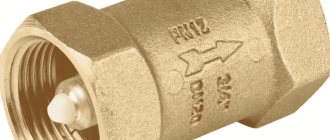
The main thing is to initially install the valve in the correct position, following the tips indicated by the arrows on the body. Signs indicate the trajectory of the water flow.
The symbol A indicates direct travel, B - perpendicular or bypass direction, AB - combined input or output.
Based on the direction, there are two valve models:
- with a symmetrical or T-shaped design;
- with asymmetrical or L-shaped.
When installed along the first of them, liquid enters the valve through the end holes. It comes out through the central one after mixing.
In the second option, the warm flow enters from the end, and the cold flow enters from below. The exit after mixing the liquid of different temperatures occurs through the second end.
The second important point when installing a mixing valve is that its drive or thermostatic head must not be positioned downward. Before starting work, preparation is necessary: turn off the water before the installation point. Next, check the pipeline for the presence of residues in it that could cause failure of the valve gasket.
The main thing is to choose a place for installation so that the valve can be accessed. It may have to be checked or dismantled in the future. All this requires free space.
Mixing valve insert
When installing a three-way mixing valve into a district heating system, there may be several options. The choice of circuit depends on the nature of the heating system connection.
When, according to the operating conditions of the boiler, such a phenomenon as overheating of the coolant in the return is permissible, excess pressure necessarily arises. In this case, a jumper is installed that throttles the excess pressure. It is installed parallel to the valve mixture.
The diagram in the photo is a guarantee of high-quality regulation of system parameters. If the three-way valve is connected directly to the boiler, which is most often the case in autonomous heating systems, a balancing valve must be inserted.
If you neglect the recommendation regarding the installation of a balancing device, significant changes in the flow rate of the working fluid, depending on the position of the rod, may occur in port AB.
Connection according to the above diagram does not guarantee the absence of coolant circulation through the source. To achieve this, you need to additionally connect a hydraulic limiter and a circulation pump to its circuit.
The mixing valve is also installed for the purpose of separating flows. The need for this arises when it is unacceptable to completely isolate the source circuit, but bypassing the liquid to the return is possible. Most often, this option is used when there is an autonomous boiler room.
Please be aware that some models may cause vibration and noise. This occurs due to inconsistency in the flow directions in the pipeline and the mixing product. Because of this, the pressure at the valve may drop below the permissible level.
Installation of separating device
When the source temperature is higher than the consumer needs, a valve is included in the circuit that separates the flows. In this case, with a constant flow rate both in the boiler circuit and by the consumer, superheated liquid will not reach the latter.
For the circuit to work, a pump must be present in both circuits.
Based on the above, general recommendations can be summarized:
- When installing any three-way valve, pressure gauges are installed before and after it.
- To avoid the entry of all sorts of impurities, a filter is installed in front of the product.
- The device body must not be subjected to any loads.
- Good regulation must be ensured by inserting devices in front of the valve that throttle excess pressure.
- When installed, the valve must not be above the actuator.
It is also necessary to maintain straight sections before and after the product recommended by the manufacturer. Failure to comply with this rule will result in a change in the declared technical characteristics. The warranty on the device will not apply.
Prevention
- To ensure protection from the arrival of neighboring bedbugs, you need to seal all the cracks, put a fine mesh on the ventilation shafts, and close the cracks in the through sockets.
- There should be no unnecessary or unnecessary things at home, these are the places where bedbugs can live.
- Bed linen and clothes should be washed at maximum temperatures.
- Constantly clean the apartment, reaching all the far corners.
- When purchasing new furniture for your apartment, you need to look at it very carefully.
How to choose a reliable valve
In the design of the heating system, it is necessary to clearly define the maximum permissible pressure values. The productive capacity of the boiler or pump, volume, and circulation features of the temperature of the working environment are also taken into account. Based on this, the type and design features are selected. Of the previously listed types, users are recommended to use spring-loaded safety valves. They are perfect for boilers with low power. Low or medium lift devices are also used for hot water systems.
If the working fluid is discharged into the environment, an open type device should be selected. If the discharge occurs into the drain, then a housing design with a threaded outlet outlet is used.
The traditional blast valve is affordable and easy to install. This device protects well a closed heating system with a gas or electric boiler, since if an accident occurs, heating stops immediately. It is also not recommended to purchase cheap Chinese fittings. It is unreliable and leaks immediately after the first explosion.
Advantages and disadvantages
This type of fittings has its pros and cons.
Users include the following advantages of the device:
- compactness and simplicity of design;
- the ability to regulate temperature in all parts of the heating system;
- the ability of the faucet to distribute coolant with different temperature values to individual areas of the household.
However, household triple-way valves are not suitable for high-pressure lines. They are not suitable for pipes with a cross-section of more than 40 mm.
Thermal mixing valve design and operating principle
Like most parts and structural elements of a solid fuel boiler, the three-pass or also has a simple and understandable design. It includes:
- main body;
- spring-loaded rod;
- two dampers, disc type;
- thermostatic element (head with fixed positions).
The diagram shows in detail the mechanism in cross-section, where and how its main elements are located.
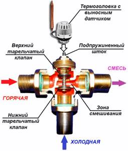
Looking at the design of the device, it is not difficult to understand the principle of operation. Let's take a closer look at the processes taking place.
During normal operation of the heating system, the main dampers, located linearly, are in the open position. Insufficiently hot water flows freely from the boiler into the heating circuit.
The thermostatic head, equipped with a temperature-sensitive liquid sensor, is in the standard position. If an emergency situation occurs, for example: coolant begins to flow into the system from the boiler side, the temperature of which exceeds the specified parameters. The temperature control sensor is activated, driving the rod. The operating mechanism closes the main, direct-flow passage, while simultaneously opening a passage from the side through which cold water flows. As a result of mixing water of different temperatures, the temperature equalizes to the established norm. The coolant, already at normal temperature, leaves the device through the pipe into the heating system. The adjustment of the thermostatic head of the device is determined by the degree to which the bellows with the expanding liquid is pressed onto the rod. Accordingly, determines the sensitivity of the device.
The moment the device operates is determined by adjusting the head, set to a certain temperature.
If the water continues to heat up as a result of the actions taken, the device shuts off the main incoming flow, allowing access to cold water from the third pipe. The rod in this case is in the lowest position. Water from the third pipe is already mixed into the main flow. When the temperature of the coolant changes downward, the rod, under the action of the sensor, reduces the pressure, opening access to hot water.
In order to achieve proper operation of the entire mechanism, it is necessary to strictly comply with the requirements for its installation. can be installed in a right-handed or left-handed version, both on the return and on the supply circuit. During operation, the device requires absolutely no maintenance.
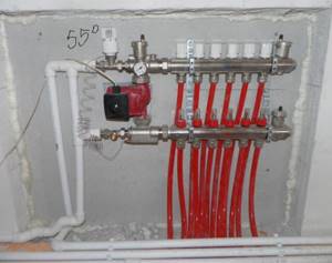
Procedure for setting up the mixing unit
When work has been completed in accordance with the connection diagram for the mixing unit for a heated floor, its operation requires adjustment. The installation process of the units is simple; you only need to join the pipes.
As for the settings, this work is performed in a certain sequence.
Stage 1 . The servo drive (thermal head) is removed so that it does not affect the unit during setup.
Stage 2 . The bypass valve is set to a maximum of 0.6 bar. If the device accidentally triggers while setting up, the result will not be correct. For this reason, it should be placed in a position where this cannot happen.
Stage 3 . Next, determine the installation of the balancing valve. Number 1 indicates the radiator circuit, 2 indicates the circuit of the heated floor system.
To do this, use the formula:
t1 – temperature of the working medium in the supply pipeline of the high-temperature circuit;
supply t2 – temperature of the coolant in the supply pipe of the floor circuit;
t2rev – water temperature in the return of the heated floor circuit.
Kυт – coefficient equal to 0.9.
If, for example, t1 = 95 °, t2 feed = 45 ° and t2rev = 35 ° are substituted into the formula, then Kυb will be equal to 4.05.
This value must be set on the balancing device.
Stage 4 . Next, the pumping equipment is set up. To do this, you will need to find out the water flow in the floor heating system together with the collector and the amount of pressure loss in the circuit behind the mixing unit.
The heat carrier flow in the floor circuit is determined using a simple formula:
G2 – coolant flow in the secondary floor heating circuit;
Q – the sum of the thermal power of devices that are connected after the mixing unit;
c – heat capacity of the coolant, in the case of water c = 4.2 kJ.
If we substitute the digital values into the formula, then G2 = 857 kg/hour or 0.86 m³/hour.
To find out the pressure loss in the heated floor circuit, a hydraulic calculation is done. The pump speed is determined using special graphs. First, mark the point corresponding to the flow rate and pressure of the pump. The curve above the obtained point reflects the speed of the pumping equipment.
The resulting flow rate is 0.86 m³/hour, and the pump pressure is 4.05 mV.st. The pressure loss in the circuits after the node is calculated with a margin of 1 mv.st., total ΔPн = ΔPс + 1 = 4.05 +1 mv.st.
When, when setting up a mixer for heated floors with your own hands, it was not possible to calculate the pump, this step is skipped. In this case, the pumping equipment is set to a minimum. If later, during the process of balancing the heating system, it becomes clear that the speed is not enough, then the pump is set to a higher parameter.
Stage 5 . Begin balancing the floor heating lines. First of all, close the balancing-shut-off valve on the radiator circuit. Next, remove the cap from the valve and turn it, moving clockwise until it stops, using the hex key.
The circuit branches are regulated using balancing valves. When there is only one line after the mixing unit, this process is not required.
Balancing is performed as follows:
- Open the regulators to maximum.
- On the branch where the flow deviation is the largest (the difference between the actual indicator and the design one), the valve is closed to the required value.
- The remaining branches of the system are regulated in the same way.
- If the flow goes wrong after balancing the branches, it still needs to be corrected.
- If it is not possible to set the flow rate even with the valves open, the pumping equipment should be switched to a higher speed.
Stage 6 . Connect the floor mixing unit with the rest of the heating devices. For this purpose, a balancing-shut-off valve, which was previously closed, is opened on the radiator circuit to a position capable of providing the required coolant flow.
When setting up a mixing unit for a heated floor with your own hands, this indicator can be controlled using flow meters or in the return pipeline.
The coolant flow in the radiator circuit is calculated using the formula:
All digital values are known, if you substitute them into the formula, then G1 = 142 kg/hour or 0.14 m³/hour.
Stage 7 . Start setting up the bypass valve. They set the pressure value on it, which should be 5 - 10% less than the maximum pressure of the pumping equipment at a given speed. This value can be found in the instructions for the pump. The bypass valve of the pumping equipment is opened only when it is working to build up pressure while there is no water flow. This device is set to a pressure of 0.54 - 5% = 0.51 bar.
Stage 8 . Check the correct functioning of the mixing unit. Confirmation of the uniform heating of the heated floor branches and the correctness of the temperature ratio in the circuits is the fulfillment of the following equation:
in this case, the index “p” denotes the calculated values, and the index “f” – the actual ones.
In the case where the equality is not satisfied, then close the balancing shut-off valve located on the radiator circuit by ¼ turn, after which the readings are taken again and calculations are performed.
If equality is observed, it is considered that the mixing unit is operating correctly. After this, the servo drive is returned to its place, protective caps are placed on all elements where necessary and the screw on the balancing device is tightened.
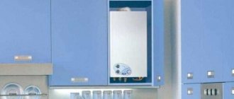
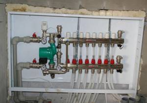
The mixing heating unit is placed in a manifold cabinet, which is usually located in a room where a heated floor is installed. It can also be placed next to the heating boiler, if distance allows. You can install the elements of the mixing unit yourself.
You need to know that a huge disadvantage of arranging a heated floor structure without a mixing unit and a collector is that then it is necessary to minimize the heat loss of water when moving it from the heater to the circuit, which will require a number of measures to insulate the building and its elements.
To constantly maintain a comfortable thermal balance in the house, an element such as a three-way valve on the heating system is included in the heating circuit, which evenly distributes heat throughout all rooms.
Despite the importance of this unit, it does not have a complex design. Let's look at the design features and operating principles of a three-way valve. What rules should you follow when choosing a device and what nuances are present in its installation.
Components
Installation of a warm water baseboard. (Click to enlarge)Warm water-type baseboard consists of:
- front panel (there are special holes on it through which the air flow functions);
- rear panels (protects the wall from exposure to high temperatures, is responsible for the ease of installation of the heating device);
- heating radiators (have dimensions - 1000 mm * 40 mm * 160 mm, the main function is heating);
- side plugs, rotating.
- heat exchange module (characterized by two tubes through which hot water flows).
Internal organization
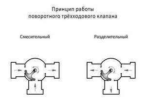
There are two types of rotary valves - globe valves and rotary valves. They differ in their internal structure and the type of force applied for adjustment.
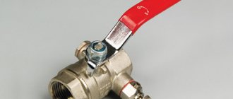
The three-way rotary valve has a ball valve. It rotates, blocking one direction and opening another (see figure). The internal structure of such a valve is similar to a ball valve.
Operating principle of a three-way rotary valve
A seated three-way valve has a stem with one (in the mixing) or two (in the separating) shut-off devices (see figure). They are metal balls that fit tightly into a socket. When one of them blocks the flow, the second is completely open.
Design
The structure of a three-way valve includes two two-way valves combined in a single body. At the same time, they regulate the intensity of the coolant flow so that they can influence the temperature of hot water in radiators and underfloor heating pipes.
The thermostatic mixing valve consists of the following elements:
- metal case;
- steel ball or rod with locking washer;
- fastening couplings.
If the valve is equipped with a stem, it can be connected to an electromechanical actuator. Then the control of coolant flow and temperature can be automated. Manual valves are usually equipped with metal balls. The principle of operation of such devices is similar to the operation of a kitchen faucet.
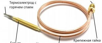
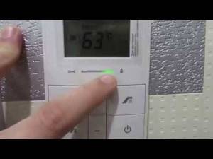
Setting up, adjusting the SIT gas valve
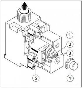
Gas valve SIT Gas valve SIT.
1 - gas pressure measuring fitting at the valve outlet, in front of the burner; 2 — adjusting nut for maximum gas flow; 3 — adjusting screw for minimum gas flow; 4 — cover of the adjusting device; 5 - gas pressure measuring fitting at the valve inlet in the gas network. Manufacturers of double-circuit gas boilers of many brands install a gas valve from the Italian company SIT on their boilers. The maximum and minimum power settings of the boiler burner are made by rotating the adjusting screws located on the valve body.
The boiler manufacturer Protherm Gepard (Panther) installs the SIT 845 Sigma gas valve on some versions of the boilers instead of the Honeywell gas valve. Such a gas valve is also found in gas boilers of the Vaillant series.
In the service menu of Protherm boilers with a SIT valve, lines d.52 and d.53 are missing.
How to regulate the minimum and maximum gas pressure at the outlet of the gas valve, see below in the video. The setup principle does not change.
The normal dynamic gas pressure at the gas valve inlet should be in the range of 1.3 - 2.5 kPa (13 - 25 mbar or 132 - 255 mm water column). If during measurement the dynamic pressure value falls outside the specified limits, then you must contact the gas service.
In order to change the minimum gas pressure at the valve outlet, in front of the burner, rotate the adjusting screw counterclockwise.
To change the maximum pressure, rotate the adjusting nut counterclockwise.
Installation and operation
To ensure successful installation of a three-way valve, it is important to follow the drawings and step-by-step instructions. also need to pay attention to several nuances of the upcoming installation:
To properly install a three way valve, it is important to follow the drawings and step-by-step instructions
- On the body of the tee there is a special diagram with arrows that show in detail the direction of water flow. Its presence significantly simplifies installation work and allows you to quickly and accurately connect important components.
- When welding metal mechanisms, the temperature flow in the joint area must not be allowed to exceed +100 °C. It is important to ensure that scale or dirt does not penetrate the system, otherwise this can lead to irreparable consequences.
- To install the tee, you need to choose a place that will be easy to reach for repairs or maintenance. If the tap has to pass insufficiently high-quality liquid, it is recommended to additionally equip it with filter units.
- The method of fixing the product can be either vertical or horizontal. This does not affect work efficiency in any way. As for the valve, it is installed directly in front of the circulation pump.
In order for the tee to function for a long time, reliably and efficiently, it is necessary to take into account the operating rules and maintain it on time. The service life of the device depends on proper and correct use.
Drive types and selection criteria
Automatic valve with electric drive
By type of drive, the models are:
- Mechanical
, the separator is installed manually. To monitor temperature indicators, a thermometer is installed on each incoming pipe. - Automatic
, the movement of the membrane depends on the temperature and is carried out independently.
- Thermostatic
, in which the sensitive element expands under the influence of temperature and begins to put pressure on the valve stem, mixing cold flows with hot ones. - Electrical
, in which signals are supplied from the control unit. - Cap type
, the tap is controlled by pressing the head on the drive rod; the drive is applicable when installing a floor heating system.
Nuances of choosing a device
The following guidelines are general when selecting a suitable three-way valve:
- Reputable manufacturers are preferred. Often on the market you can find low-quality shut-off valves from unknown companies.
- Copper or brass products have greater wear resistance.
- Manual control is more reliable, but less functional.
The key point is the technical parameters of the system in which it is supposed to be installed. The following characteristics are taken into account: pressure level, the highest temperature of the coolant at the point of installation of the device, the permissible pressure drop, the volume of water passing through the valve.
Only a valve with the correct capacity will work well. To do this, you need to compare the performance of your plumbing system with the throughput coefficient of the device. It is mandatory indicated on each model.
For rooms of limited space, such as a bathroom, it is irrational to choose an expensive valve with a thermomixer.
Large areas with heated floors require a device with automatic temperature control. The guideline for selection should also be the product’s compliance with GOST 12894-2005 .
replacement and repair of a three-way valve on a Navien ace atmo boiler.
| Dismantling, replacement and repair of a three-way valve on the NAVIEN ACE Atmo boiler |
Click to view | Video instructions for dismantling, replacing and repairing NAVIEN ACE Atmo boilers... |
| Tags: |
| Navien - three way valve |
Click to view
Boilermaster The Navien boiler suffers from a three-way valve problem. And oddly enough, the external valve...
| Tags: |
| Navien three-way valve price for repair or replacement! |
Click to view
How to revive or extend the life of a Navien boiler three-way valve.
| Tags: |
| Three way valve Navien repair |
Click to view
Boilermaster Three-way valve Navien, Celtic - Arleria, Daewoo. Detailed review, repair options and possible...
| Tags: |
| Three-way valve Navien, Celtic - Arleria, Daewoo. Detailed review. |

Click to view
My channel, subscribe, it will be interesting.
| Tags: |
| replacing a 3-way valve on a Navien boiler (Navien) |
Click to view
Video instructions for dismantling, replacing and repairing NAVIEN ACE Turbo boilers...
| Tags: |
| Repair of three-way valve ARDERIA and partially NAVIEN |
Click to view
The Navien Ace 24K gas boiler has malfunctioned. There are loud clicks, turbine noise, the pressure of hot water has decreased and...
| Tags: |
| Dismantling, replacement and repair of a three-way valve on the NAVIEN ACE Turbo boiler |
Click to view
three-way replacement.
| Tags: |
| 1/2 Problem with the Navien Ace 24 K boiler. Sound noise, knocking, grinding. Problem solved. |

Click to view
Three-way valve malfunction Arderia Celtic Three-way valve ...
| Tags: |
| Repair Gas boiler Navien Ace Atmo ACE - 13 |
Click to view
Navien repair of three-way boiler valve
| Tags: |
| Three way valve malfunction Arderia Celtic |
Click to view
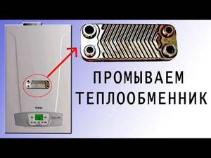
Navien Ace 13K boiler Disassembling the boiler and cleaning the heat exchanger This video is not an encouragement to action...
| Tags: |
| Navien repair of three-way boiler valve |
Click to view
What to do if the batteries heat up, but the hot water does not. Let's analyze the most typical malfunction of wall...
| Tags: |
| Disassembling the boiler and cleaning the heat exchanger Navien Ace 13K |
Click to view
My video review and review of the NAVIEN gas boiler!
| Tags: |
| The most common malfunction of double-circuit gas boilers |

Click to view
The first boiler start-up is a process...
| Tags: |
| Gas Double-Circuit Boiler NAVIEN 24 Review and Feedback! |
Click to view
Where to install the mixing valve and where to install the distribution valve. It turns out I can, both directly and...
| Tags: |
| First boiler start-up |
Click to view
The water in the gas boiler does not heat up. Gas boiler repair.
| Tags: |
| Three-way valve. We install it correctly. |
Click to view
NOT TO PAY FOR WHAT IS EASY TO DO YOURSELF. Do-it-yourself descaling of the boiler In this video...
| Tags: |
| Why doesn't hot water flow from a gas or bithermal boiler? |
Click to view
Video instructions for dismantling, replacing and repairing NAVIEN NCN boilers https://www.navien. https://shop.navien..
| Tags: |
| Flushing the heat exchanger. Geyser. Citric acid |
Click to view
How to repair a three-way valve (heating works, turn on DHW priority, does not respond...
| Tags: |
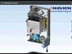
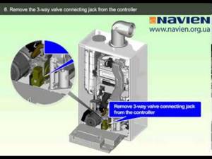
| Removing the three-way valve |
Click to view
Video instructions for dismantling, replacing and repairing NAVIEN ACE Atmo boilers...
| Tags: |
| Three-way valve Navien Ace Repair |
Click to view
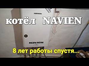
Review of the NAVIEN ACE gas double-circuit boiler for 310 m2 after 8 years. How many breakdowns were there, what kind...
| Tags: |
| Dismantling, replacement and repair of the hydraulic system on the NAVIEN ACE Atmo boiler |

Click to view
Video instructions for dismantling, replacing and repairing NAVIEN ACE Atmo boilers...
| Tags: |
| 8 years later. Is it worth taking? Boiler NAVIEN ACE. buderus vaillant reaction. what for what |
Click to view
Video instructions for dismantling, replacing and repairing NAVIEN ACE Atmo boilers...
| Tags: |
| Dismantling, replacement and repair of the secondary heat exchanger on the NAVIEN ACE Atmo boiler |

Click to view
Video instructions for dismantling, replacing and repairing NAVIEN ACE Atmo boilers...
| Tags: |
| Dismantling, replacement and repair of the monometer on the NAVIEN ACE Atmo boiler" rel=»spf-prefetch |

Click to view
Description missing
| Tags: |
| Dismantling, replacement and repair of the pump on the NAVIEN ACE Atmo boiler" rel=»spf-prefetch |
Click to view
Description missing
| Tags: |
| We disassemble the three-way valve of the NAVIEN gas boiler" rel="spf-prefetch |
Rules for operating a three-way valve
The “tee” installed in the system requires periodic inspection for wear and leaks. If a leak is detected, you can try tightening the threaded connection. If the leak cannot be eliminated, the mixer will have to be disassembled. Very often it is the O-rings that wear out. Replacing them and cleaning the elements from scale extends the life of the device.
To reduce the wear of the device, it must be periodically lubricated with a special plumbing product.
Common mistakes and problems when installing a three-way valve
Errors made when installing a “tee” not only shorten its service life, but also negatively affect the operation of the entire pipeline:
- Incorrect connection of pipes increases hydraulic resistance.
- The use of models with fluoroplastic seals in systems with operating temperatures above 150 °C will require replacing the three-way mixer after 2-3 months.
- Installation in a hard-to-reach location will complicate preventive maintenance procedures.
Expert advice
- During installation, the brass body is easily damaged. To prevent this, it is better to place a thick fabric gasket under the wrench.
- To install a three-way valve on plastic pipes, special adapters are needed.
- Instead of a “tee”, you can use 2 conventional two-way valves. They must work according to a reverse pattern: when one opens, the other closes.
How does a three-way valve work in a heating system?
The principle of operation of the valve is to mix water flows with different temperatures. Why do you need to do this? Without going into technical details, we can answer this way: to extend the life of the heating boiler and make it more economical.
A three-way valve mixes heated water with cooled water after passing through the heating devices and directs it back to the boiler for heating. Everyone can answer the question of which water to heat faster and easier - cold or hot.
Simultaneously with mixing, the valve also separates the flows. There is a natural desire to automate the management process itself. For this purpose, the valve is equipped with a temperature sensor with a thermostat. In this case, an electric drive works best here. The quality of functioning of the entire heating system depends on the drive device.
- Such a valve is installed in those places of the pipeline where it is necessary to split the circulation flow into two circuits:
- With constant hydraulic mode.
- With variable.
Typically, a constant hydraulic flow is used by consumers who are supplied with a high-quality coolant of a certain volume. It is regulated depending on quality indicators.
Variable flow is consumed by those objects for which quality indicators are not the main ones. The quantitative coefficient is important to them. That is, for them the supply is adjusted according to the required amount of coolant.
There are also two-way analogues in the shut-off valves category. What is the difference between these two types? The three-way valve works completely differently. In its design, the rod cannot block the flow with a constant hydraulic regime.
It is always open and adjusted to a certain volume of coolant. This means that consumers will receive the required amount in both quantitative and qualitative terms.
Essentially, the valve cannot shut off the supply to a circuit with constant hydraulic flow. But it is capable of blocking a variable direction, thereby allowing you to regulate pressure and flow.
If you combine two two-way valves, you get a three-way design. In this case, both valves must operate reversibly, that is, when the first one closes, the second one must open.
Types of three-way valves according to operating principle
- According to the principle of action, this type is divided into two subtypes:
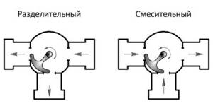
- Mixing.
- Separating.
Just by the name you can understand how each type works. The mixer has one output and two inputs. That is, it performs the function of mixing two flows, which is necessary to lower the temperature of the coolant. By the way, this is an ideal device for creating the desired temperature in underfloor heating systems.
Regulating the temperature of the exhaust ceiling is quite simple. To do this, you need to know the temperature of the two incoming streams and accurately calculate the proportions of each in order to obtain the required temperature regime at the output. By the way, this type of device, if installed and adjusted correctly, can also work on the principle of flow separation.
A three-way separation valve splits the main flow into two. Therefore, it has two outputs and one input. This device is commonly used to separate hot water in hot water systems. Experts often install it in air heater trims.
In appearance, both devices are no different from each other. But if you look at their cross-sectional drawing, there is one difference that immediately catches your eye. The mixing device has a rod with one ball valve.
It is located in the center and covers the saddle of the main passage. In a separating valve there are two of these valves on one stem, and they are installed in the outlet pipes. The principle of their operation is as follows: the first closes one passage, pressing against the saddle, and the second at this time opens another passage.
- Modern three-way valves are divided into two types according to the control method:
- Manual.
- Electric.
More often you have to deal with a manual version, which is similar to a regular ball valve, only with three pipes - outlets. Electrical automatic systems are most often used for heat distribution in private housing construction.
Like any device, a three-way valve is determined by the diameter of the supply pipe and the coolant pressure. Hence GOST, which allows for certification. Failure to comply with GOST is a serious violation, especially when it comes to pressure inside the pipeline.
Service life of three way valve
The period of trouble-free operation of the device is determined by:
- Design features.
- The material from which it is made.
- Compliance of its technical characteristics with real operating conditions.
Manufacturers give a guarantee of 5-7 years for steel “tees”, but with moderate intensity they can easily last 50 years. The service life of plastic models, as a rule, does not exceed 2 years.