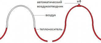
What is a heating cable?
Cable heating systems for both residential and non-residential premises are becoming increasingly widespread. The purpose of using a heating cable is to maintain the required temperature conditions. A cable that converts electrical energy into heat is called a heating cable. A cable heating system helps make life more comfortable.
Heating cable - operating principle and application
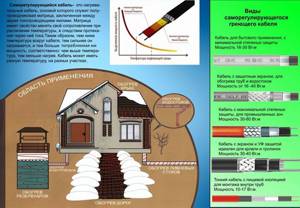
A modern heating cable functions like any electric heating device. The higher the resistance of the material to the passage of electric current, the more thermal energy is released on the heating element. The device is connected to an electrical network with a voltage of 220 V, and when electricity passes through it, it generates heat. The heating cable can be used in the following areas:
- heating of floors, walls and ceilings;
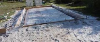
- maintaining the temperature regime for hardening concrete becomes especially important in cold weather conditions;
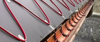
- de-icing of roofs, drainpipes and stairs;
- heated mirrors to eliminate condensation;
- soil heating is widely used in greenhouses;
- preventing freezing of drainage and sewer pipes;
- maintaining the desired temperature of liquid and water, and so on.
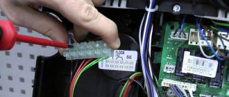
Sensor malfunctions
The sensor works in conjunction with a thermostat and measures the temperature of the heated floor. If the floor heating turns off quickly or severe overheating is observed, then you need to check the sensor.
A visual preliminary inspection of the sensor may reveal the presence of:
- burnt contacts;
- lack of system power.
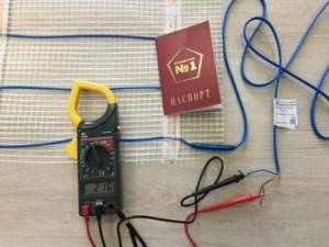
You can also determine the voltage level at a certain section of the circuit. The sensor is a resistor with its own resistance. The readings obtained from testing with a multimeter can provide valuable information about the breakdown.
With their help, you can determine which of the sensor elements (relay and capacitor) has failed or the connections are inaccurate.
Diagnostics with the device is carried out after inspection. To do this, you need to turn off the thermostat, remove the panel from the front side, then remove the installation block. Connect both terminals with a voltage of 220 W to the thermostat.
The document for the thermostat indicates the resistance of the device; usually it ranges from 5 kOhm to 120 kOhm, which depends on the body temperature of the sensor. When 5 ⁰C, its value will be about 22 kOhm, and at 40 ⁰C – 6 kOhm.
The multimeter is set to ohmmeter mode. If the indicators coincide with those declared by the manufacturer, then the sensor is working.
Therefore, independent testing of a heated floor is possible using a multimeter.
In a household with heated floors, the owner needs to have a device to check the functionality of the sensor and thermostat with heating cables.
Modern thermostats are equipped with touch screens; they can independently indicate sensor failure.
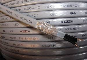
Heating cable - characteristics
When choosing a product, they are guided by the area of application. To choose a suitable cable, you need to consider its main technical parameters:
- Power. The higher this parameter, the greater the electrical energy consumption and heat generation.
- Temperature operating conditions of the cable. There are three types: high temperature (up to 190°C), medium temperature (up to 120°C), low temperature (up to 65°C).
How much does a heating cable consume?
Everyone who wants to use this invention thinks about this question. In fairness, it is worth noting that the answer depends on many factors, and no specialist will calculate the exact consumption. What does consumption depend on?
- product location;
- weather conditions;
- pipe diameter and thermal insulation;
- power and cable length;
- type of heating cable.
You can approximately calculate the flow rate when using a pipe for heating:
- We find out the nominal consumption indicated by the manufacturer, then find out the length and diameter of the pipe and make calculations. For example, the nominal consumption is 14 W/m, the pipe length is 10 m, and the diameter is 32 d, then the consumption will be 140 W.
- If there is thermal insulation, then consumption is reduced by about half.
- If the cable operates around the clock for a whole month, then multiply 24 hours by 30 days and by the consumed amount of kW/h.
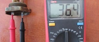
Measuring resistance with a multimeter
If there are no violations, the multimeter reading should be equal to one
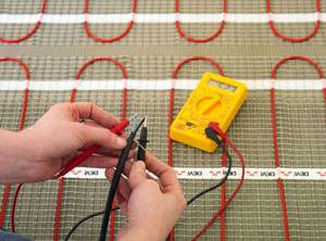
When ceramic tiles are chosen as the floor covering, until the screed and tile adhesive are completely dry, the heating cable of the system must not be connected to the network. To make sure the device is working, you need to use a special device - check the heated floor with a multimeter:
- The device is set to resistance measurement mode and the limit is set to 2000 Ohms. Make sure you set up the multimeter correctly. To do this, you need to short-circuit its probes - zero should appear on the screen.
- Find the heating cable and measure the resistance between its cores. The result was 409 ohms.
- Compare the result obtained with the data specified in the device passport. It should be taken into account that the resistance of a heated floor may depend on the ambient temperature and cable length. The permissible error is considered to be a difference in measurements of 10-15%. In this case, the user manual indicates a resistance of 360 ohms. The difference between the measurement and the value written in the document was 14%, which is considered acceptable.
- The resistance of the insulating material is measured. Switch the multimeter to 2000 kOhm mode, and ring each cable core. The instrument readings should tend to unity, which confirms that there are no violations of the integrity of the heating element braid.
Don't miss: Tiling the stove: step-by-step instructions
It is advisable to carry out a trial check at all stages of working with a heated floor. When purchased in a store together with a sales consultant, then after installing the system, pouring the screed and laying ceramic tiles.
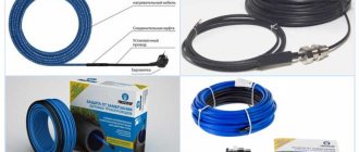
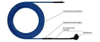
Types of heating cable
Experts distinguish two main types of products:
- Resistive, in which current conductors perform the function of heating elements. This type of heating cable for pipes is being used less and less.
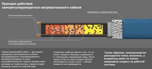
- Self-regulating is the smartest and most convenient to use. This type of self-regulating heating cable is becoming increasingly popular today.
Self-regulating heating cable
This cable consists of one to several cores, insulated from each other by a special sheath. Self-regulating heating cable can be used in various fields. It independently maintains the required operating power and the amount of heat generated depending on weather conditions. The operation of the cable depends on the resistance, that is, if it increases, the current supply decreases, due to which the power decreases. He himself identifies areas where the degree needs to be raised or lowered.
Resistive heating cable
The cable includes one or two insulated cores of a fixed length that cannot be cut independently. This type does not give the chance to change power without using thermostats. This heating cable is used for sewer pipes. There is a subtype of this cable - zonal, consisting of two parallel conductors through which current passes. The heating element is a wire attached to the cores at a fixed distance. This type of cable can be cut along the marked marks.
Tip 5. Pay attention to installation methods
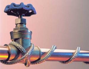
Outdoor installation
For this option, you can use any type of heating cable.
Advantages:
- Easy to install. Work can be done alone.
- Does not reduce the overall pipe capacity.
6 ways to lay outdoor cable
- It is enough to tape the conductor with special tape to small cross-section pipes. Suitable for areas with mild climates.
- Where climatic conditions are more severe, the cable is wrapped around large cross-section pipes. The lower the temperature, the denser the turns.
- When using a resistive conductor, when completing the winding, the second end can be returned to the starting point.
- We avoid superimposing one turn on another, that is, overlapping, since overheating is possible during operation.
- The average step is 5 cm.
- The material should fit snugly to the surface without sagging.
Before installation work, we prepare the outer surface of the pipe. We remove traces of corrosion and dirt from metal. The plastic one needs to be wrapped in foil.
Internal installation
Only two-core resistive heating cables are used for pipe cross-sections of 40 centimeters or more. Conductors that are inserted to a predetermined length. To use a self-regulating conductor, external protection must have a class of at least IP68.
At the point of output and connection to the network, a coupling is screwed on to seal the installation. There are restrictions: they must only be solid, without joining elements.
Tip 6. Seven basic recommendations
- For pipelines with variable temperature conditions, only a self-regulating cable is suitable. Especially in a situation where one part of the pipeline system is located indoors, and the other is underground or in the air. Resistive cable is energy inefficient.
- It is recommended to select the right insulating materials to make the system energy efficient.
- When winding, you need to clarify to what extent the bending of the material is allowed. If bent, rapid failure may occur.
- For household systems, a relay is connected to the cable to prevent current leakage.
- For the self-regulating conductor version, the use of a temperature sensor is recommended. It is set to turn on at a temperature of +3 and turn off when it reaches +13 degrees Celsius.
- When laid lengthwise, the length of the material is equal to the size of the pipe, with a certain margin. When winding, you need to take 1.6 - 1.7 pipe lengths.
- The sensor is isolated from the heater surface. It is important that the connection to the pipe is as tight as possible.
How to connect the heating cable?
Direct connection of the cable is made by connecting it to the unit that performs thermoregulation. Depending on the purpose and scope of application, linear and spiral installation are used, while the wire itself is laid either inside or outside relative to the pipes or another surface.
Most often, when selling heating cables, a thermostatic unit is included. You should try to install it so that it is not affected by the negative environment. The connection of the wires must be sealed. To do this, you can use special clamps and couplings.
Connecting the heating cable takes place in several stages:
- Cable conductors intended for connection are cut in the form of a ladder at various distances and freed from insulating material to a length of 10 mm.
- Heat-shrinkable sleeves are pulled over all existing conductors, and a joint sleeve with a large diameter is attached on top of the cable.
- The ends of the wires are mounted in sleeves and clamped with pliers on one side, and on the other hand they crimp the sleeve after inserting the other ends.
- Couplings with a small diameter are put on the wires and heated with a hairdryer; after clamping, a coupling of a larger diameter is pulled onto the connection area and also heated with a hairdryer.
- If we are talking about self-regulating types of cable, then both end wires are sealed. They are cut in the form of a ladder, a heat-shrinkable sleeve is pulled over them and also heated with a hairdryer.
- The thermostatic regulator, which is necessary to regulate the temperature, is placed close to the electrical panel. To increase safety, an RCD (automatic switching device) is introduced into the thermostatic regulator circuit.
What is included in underfloor heating?
Heated floors are made of electric cables or with infrared film. The system includes the following elements:
- Heating cable – heat source;
- Thermal sensor for monitoring cable heating;
- The thermostat, which connects the elements into the structure, starts or turns off the heating depending on the temperature parameters.
Features of using a thermostat
The thermostat automatically adjusts the voltage supplied to the wires. It connects to a regular electrical network through phase and neutral wires and looks like a small switch. Its heating is monitored by a sensor located next to the wires.
The person sets the minimum temperature, upon reaching which the heating system starts. A cable in this design can be resistive or with self-regulation of fluctuations in heat degrees and resistance levels.
Which cable is suitable for the heating system?
Calculations of the heating system largely depend on the length of the cable, changes in which will subsequently disrupt the functioning of the entire structure and damage the insulation.
Two-core cables or a pair of single-core cables are used. A wire with two cores cannot be cut or installed in places with floor loads; single-core wires are more versatile.
Checking cable resistance in a heated floor system and troubleshooting
Any electric floor must be checked for malfunctions during the installation stage. As soon as the heating elements are laid, you need to connect the power supply and observe the operation. If all systems function smoothly and without failures, then you can begin pouring the screed or laying the topcoat. For non-professionals, it is better to entrust the installation of heated electric floors to specialists, since improper handling of electrical appliances can lead to big problems.
Checking the resistance of a heated floor
All manufacturers declare the high reliability of electric heating systems, provide a guarantee, and indicate on the product a service life of up to 20 years. If everything is done correctly at the installation stage, then the warm floor will actually last for decades. But, there are also non-standard situations when the heated floor does not heat. What to do in this case? There are several reasons for this situation:
- thermostat malfunction;
- The heated floor temperature sensor does not work;
- Damage to floor heating wires.
Cable diagram for heated floors
Checking the heated floor upon purchase and after installation
Warm floors are checked upon purchase, before pouring, and if the cable breaks for repair.
The first check of a heated floor with a multimeter is carried out upon purchase. The seller is obliged to demonstrate all the functionality of the product at the request of the client. The product must be accompanied by documentation with the specified technical characteristics, insulation resistance values and mats. This data must be checked against the actual readings of a tester or multimeter.
After laying the heating elements, but before installing the floor covering or pouring the screed, it is necessary to check the operation of the heated floor a second time. To do this, you first need to make sure that the heating cable is intact. Then the system is connected to the mains and the operation of different modes is observed for some time. At this stage, it is important to ensure that the temperature sensor and thermostat are functioning correctly. Correct operation requires uniform heating of all sections of the cable. The heating temperature of the elements must change in accordance with the specified parameters of the thermostat.
If a malfunction is discovered during the installation process, it is best not to look for the problem or try to solve it, because This is most likely a warranty issue. You should contact the store where you purchased the product and replace it with a working version.
How to identify problems
Before electricity reaches the heating elements, it passes through a thermostat. This is a device that regulates the supply of current: if the floor heats up to a set temperature, the power automatically turns off. When cooling, the current flows again.
The thermostat has an electronic display that shows the voltage; to check how it works, you need to:
- dismantle the device;
- use a multimeter to measure the voltage, setting the maximum floor temperature - the sensors should show 220 V;
- then the relay knob needs to be turned in the opposite direction - set the minimum temperature - the sensors should show no voltage.
Measuring the resistance of electric underfloor heating cables
Thus, you can check whether the relay and the thermostat itself are working.
To determine the health of the heating cable, it is necessary to measure its resistance. This is done using a multimeter as follows:
Calculation of laying heated floors
- the resistance value must be divided by the voltage - 220 V - you get the amount of current that passes through the system;
- the current value must be multiplied by the voltage (220V) - the power of the electric floor is obtained, which should not deviate from that declared by the manufacturer (specified in the system passport) by 5%.
If there are deviations, they indicate a malfunction of the heating elements.
Fault detection methods - how to check correctly
There are two ways to check the functionality of the system:
- First . It consists of visually inspecting the cable and components for damage. But it allows you to detect only visible defects, such as burnt equipment, lack of power supply in the building, broken cable and others. But this method is not very informative, and it is not always possible to identify the reason for the lack of heating.
- Second . This method makes it possible to find a breakdown using a multimeter. It allows you to find out the voltage in the network. Before checking the heated floor with a multimeter, the temperature regulator is removed from the wall and the voltage, which should be 220V, is measured using special probes. If this parameter is normal, then the cause of the malfunction lies in one of the system elements.
First of all, perform a visual inspection to make sure there is power supply to the floor. Next, they look for melted or burnt parts. If nothing can be detected, use a multimeter.
You need to measure the cable resistance and divide it by 220 to get the voltage value in the electrical network. This value reflects the amount of current passing through the system. This figure is then multiplied by the voltage to determine the power consumption. It is necessary that it corresponds to the power of the heating system, which is reflected in the passport.
When the received parameter is greater, this means that the cable insulation is damaged. If the value is less than that specified in the passport, then you need to read the instructions on how to check the heated floor for a break. In the absence of documentation for the equipment, it is considered that the power is conditionally 150 W/m2.
If the resistance of the heated floor on the multimeter is zero, then the system is disabled by a short circuit. In this case, equipment repair will be expensive, and it is difficult to find such damage on the cable field. If heating occurs using infrared flooring, you need to lift the floor covering, find the damaged area and replace it.
What does high power consumption mean?
If a comparison of values shows a high power consumption, this indicates that there are short circuits resulting from a violation of the integrity of the wire insulation. In this case, part of the floor will heat up very much, while the other will not work. In this mode, the entire system will not work for a long time, and a lot of electricity will be consumed, which, of course, is uneconomical.
Power of electric mats This problem can only be solved if it is possible to remove the finishing coating. If the cable was laid under a screed, this will not be possible.
What does low power consumption indicate?
If the amount of power consumed is much less than that indicated in the product data sheet, then this indicates an open circuit. In this case, the resistance will be very high, which may lead to cable burnout. You can determine the location of the break if it is possible to remove the entire finishing coating or dismantle a section of it.
Measuring the insulation resistance of a heated floor with a megohmmeter
- you need to disconnect the heated floor from the thermostat and the electrical network;
- The break point is searched using a high-voltage generator and an audio detector. The operating principle of such a device is similar to a metal detector. It passes along the surface of the floor and signals a loss of current - this is the break point;
Diagram of the underfloor heating thermostat in the electrical network
- Having identified a break, the coating is dismantled in this place;
- damaged wires are stripped, connected with sleeves and compressed with press pliers;
- the heat-shrinkable sleeve is heated with a hair dryer, and when it cools, it shrinks and becomes a sealant for the restored wire;
- Next, the floor covering is installed.
Source
Subscribe to the newsletter
Types of heating cable damage
Let's look at the most common types of heating cable damage.
As a rule, damage can be mechanical or due to overheating.
Mechanical damage to the cable can lead to its breakage, and as a result to a short circuit.
Mechanical damage usually occurs due to the following reasons:
- Carrying out various works after laying the cable, without taking into account its layout, i.e. drilling holes in the floor covering, installing equipment, etc., not taking into account the location of the cable during installation;
- Too frequent pitch of the cable snake during installation. Often the cable cannot withstand mechanical stress due to the bending radius being too small.
- Damage to couplings. Often, under the influence of a humid environment, oxidation of the contacts of the heating cable core occurs and, as a result, their oxidation. This leads to the destruction of the coupling connecting these contacts.
The most common causes of cable overheating:
- Local overheating can occur if the cable is located under furniture that almost never moves, or under carpets.
- When laid, the cable intersects with other cables, tubes or materials that, in their thermal conductivity, contrast with the screed or base in which the cable is laid. This creates a temperature difference, which subsequently leads to constant overheating of the cable.
Of course, not all possible causes of cable damage or overheating are listed above. Most of them can be avoided by strictly following the heating cable installation instructions.
How to check a heating cable with a multimeter
How to check the heating cable for integrity after its installation? It is necessary to ring the heating cable; this can be done using a multimeter. This device measures the resistance of the cable cores.
To do this, set the multimeter to the electrical resistance measurement mode. We apply the multimeter probes to the cable cores respectively. At this moment, a number is displayed on the device screen; this is the actual resistance of the cable (for example, 216 Ohm/m). We compare it with the resistance indicated on the marking or in the cable passport (for example, 208 Ohm/m ± 10%). If the readings are within the values indicated on the marking, then this cable meets the declared characteristics and is not damaged.
If a figure close to infinity is displayed on the multimeter screen, then the cable has a break. After you can check the functionality of the heating cable, you can begin to localize the damage.
How to search for damage using a thermal imager and perform repairs
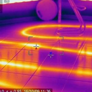
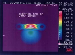
It is better to start searching for damage to the heated floor using a thermal imager. This is the most visual and fastest way to diagnose heating cable damage.
This device displays on its screen an image of infrared radiation from a heated floor. The uniformity of this radiation indicates that there should be no damage.
However, if the thermal imager shows a picture of uneven thermal radiation, then there is still damage, and the heating system will have to be repaired.
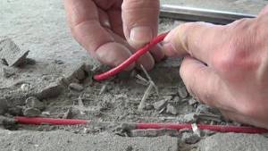
To do this, you first need to open the floor covering at the site of the suspected cable fault (naturally, the system must be disconnected from the network at this moment). It is necessary to break the tie very carefully so as not to further damage the cable.
Then it is necessary to strip the cable at the break point and connect the current-carrying conductors and the shielding braid of the cable using insulated sleeves. Heat shrink tubing is placed over this connection. The tube can be shrinked using a hair dryer.
Then we restore the floor covering: if necessary, fill in a cement screed, leaving no air voids, and after it dries, lay the floor covering. If these are floor tiles, then it is recommended to wait until the tile adhesive and screed have completely dried. As a rule, this process takes up to 21 days (for screed) and from 24 to 48 hours (for tile adhesive), depending on the room temperature. After this, we turn on the heating system to the network.
Why does the heating cable not work if the test showed that the cable is normal?
After checking the heating cable for continuity with a multimeter, it may turn out that the cable is OK, but the system still does not work.
In this case, the most likely causes of the system malfunction are:
There is a fault in the switchboard. We recommend checking the residual current device (RCD), automatic or difavtomatic, depending on what type of switch the electric heating system in your panel is connected to.
Low voltage in the electrical network can also cause improper operation of the heating cable. In this case, installing a voltage stabilizer may be a solution to the problem.
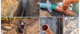
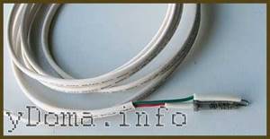
How and why is a heating cable used? You already have a house, a water intake unit, a well and a pump. All that remains is to lay communications between the house and the well. It’s just that you can’t “bury yourself” below the freezing point - either the groundwater is high, or the root rock (the one that starts immediately after the bayonet of the shovel). In these cases, a heating cable is indispensable.
Pipe heating cable: how does it work?
First, let's figure out what types of heating cables for water supply systems are and what kind of mechanism underlies their operation.
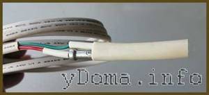
The heating cable can be resistive and self-regulating. Resistive is divided into two types - 1-wire and 2-wire. The principle of operation is simple. The cable has a very high resistance alloy strand running through it, and when electric current runs through it, it generates heat. If there is only one core, the cable is plugged into one end of the socket, goes along the heating point, then returns and goes into another socket. To adjust the heating mode of the water supply, additionally installed temperature sensors and thermostats. We measure the required amount of cable, cut it and make an end seal, thereby closing the loop.
Which cable is better? Checking the heating cable
To assess the quality of a self-regulating heating cable, it is necessary to study the passport with the declared characteristics, the certificate of electrical and fire safety, as well as its main external and operational properties.
Most manufacturers state general specifications for power, maximum operating temperature, and service life. These parameters are not standardized values, that is, they are not tested during certification. The certificate confirms the safe operation of the heating cable under appropriate operating conditions.
Thus, the cable performance characteristics stated in the manufacturer’s catalogs can only be verified experimentally. Some studies are quite simple and give a general idea of the quality of the cable. More complex tests are carried out in specialized laboratories, subject to the conditions and technology for measuring the parameters under study.
This example examines the characteristics of a self-regulating heating cable from three different manufacturers. Cable without braid, linear power 16 W/m, used for heating household pipelines under thermal insulation.
Characteristics of self-regulating heating cable
Supply voltage, Volt
Some manufacturers simply indicate the supply voltage range, for example: 220 - 275 Volts, without additional comments and a table of conversion factors for the allocated power depending on the supply voltage. The fact is that the rated power indicated in the documentation and advertising brochures of manufacturers is standardized at a supply voltage of not 220, but 230 or 240 Volts. This voltage must be confirmed with the manufacturer.
Moment one. Variations in supply voltage must be taken into account to estimate the power delivered by a self-regulating cable. Manufacturers offer special tables with coefficients for recalculating the allocated power depending on the deviation of the supply voltage from 230/240 Volts. For example, for some cable models this coefficient is 0.9. Accordingly, at a supply voltage of 220 Volts, the linear power of this cable will decrease by 10%. This fact must be taken into account at the time of design.
Second moment. For each brand of self-regulating cable, there are restrictions on the supply voltage. For example, for cables designed for a voltage of 230 Volts, a supply voltage exceeding 275 Volts is unacceptable. An increase in the supply voltage (for example, due to installation errors, sometimes a voltage of 380 Volts is supplied to the heating section) causes increased heat generation in the matrix and its rapid degradation and complete cessation of heating, i.e., cable failure.
Rated power per linear meter of cable, W/m at the indicated temperature in degrees Celsius
Due to the fact that this is the main technical characteristic of this product, we will dwell on it in more detail.
The significant dependence of heat generation power on temperature dictates certain rules for rationing and measuring thermal power. The power of a self-regulating tape is rated under the following standard conditions - a piece of cable being measured is installed on a metal pipe with a diameter of at least 50 mm. so as to ensure good thermal contact. Coolant is pumped through the pipe at a temperature of 10 ± 0.5 °C. (in some cases, measurements are carried out at 5 °C). The pipe with the cable is covered with thermal insulation with a thickness of at least 20 mm. The rated power indicated in manufacturers' catalogs is the power measured under standard conditions. To remove the dependence of power on temperature, it is necessary to set and maintain the appropriate pipeline temperature.
The dependence of power on temperature is measured in such an installation for at least three pipeline temperatures. The power curves of specific brands of cables versus temperature, given in the catalogs of supplier companies, show the dependence of the heat release power on the temperature of the pipe, and not on the temperature of the cable. This is a very significant point that should be taken into account when using self-regulating tapes. The following figure shows a similar relationship for the BTV2-CT cable from Tyco - Raychem.
Under other conditions, such as poor contact with the heated object, the power generated by the self-regulating cable will not correspond to the reference curve. If a self-regulating cable is suspended freely in the air, then due to the deterioration of heat transfer conditions, the measured power will be approximately 30% less than the normalized one.
Conclusion: It is important to ensure proper control over installation work on site to ensure the required quality of work. Otherwise, the electric heating system based on self-regulating cables will operate with a drop in power relative to the design one, and this fact will lead to a significant overconsumption of electricity.
Starting current of the heating cable, Ampere
Self-regulating cables, in addition to the rated power and the dependence of power on the temperature of the pipe, are characterized by the value of the specific starting current depending on the temperature at the moment of switching on. This is the current value, normalized to one meter of cable, that occurs at the moment the power is turned on. The inrush current mostly drops off within the first minute, but complete stabilization takes approximately 5 minutes. The maximum absolute value of the inrush current is determined by the length of the heating cable, the temperature of the object and the design of the particular heating cable.
The primary area of application of self-regulating cables is heating of pipelines and tanks operated at subzero ambient temperatures. As a rule, systems are started when both pipes and thermal insulation are cold. For the purposes of designing and calculating the characteristics of a heating system at the time of start-up and operation, it is necessary to know the properties of self-regulating tapes at low temperatures. Based on their design, we can conclude that the lower the temperature, the lower the resistance of the cable heating matrix and the higher the inrush/starting current.
Due to the fact that the technical characteristics of circuit breakers against short circuits, overcurrents, earth leakage protection, the cross-section of power cables, and therefore their price directly depend on the magnitude of the starting current, design organizations and end customers should pay attention at this time close attention.
Below in the text are presented the results of studies of three brands of cables in the range from +10 to – 40 °C. The 23FSLe2-ST cable is mainly installed on pipelines with a diameter of up to 100 mm. The 31FSR2-ST cable is used for heating larger pipelines. Both cables operate stably under voltage at temperatures not exceeding 65 °C. When switched off, they can withstand up to 85°C. The medium-temperature cable 55FSS2-SF has a heat-resistant matrix, and the insulation and sheath are made of fluoropolymers.
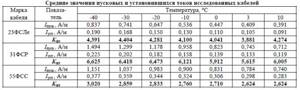
Brief characteristics of the studied cables are given in the following table.
Studies of the dependence of characteristics on temperature were carried out in a climate chamber. At the same time, such air circulation in the chamber and other experimental conditions were ensured under which the power values measured in the chamber were close to the results obtained in a standardized installation. Measurements were carried out at temperatures: +10; +3; 0; -10; -20; -thirty; -40°C. Each cable brand was represented by three samples. Upon reaching the specified temperature, the sample was kept in the chamber for 1 hour. Then the rated voltage was applied to the sample. The starting current and its decrease as the cable warmed up were recorded. A typical table of measured values is shown below.
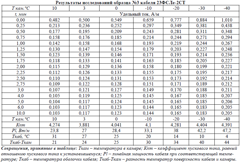
The following figure shows graphs for reducing the inrush current of the 23FSLe2-ST cable, constructed according to the data in this table. As the temperature decreases, both the starting and steady-state current increases. There is also a slight increase in the starting current coefficient.
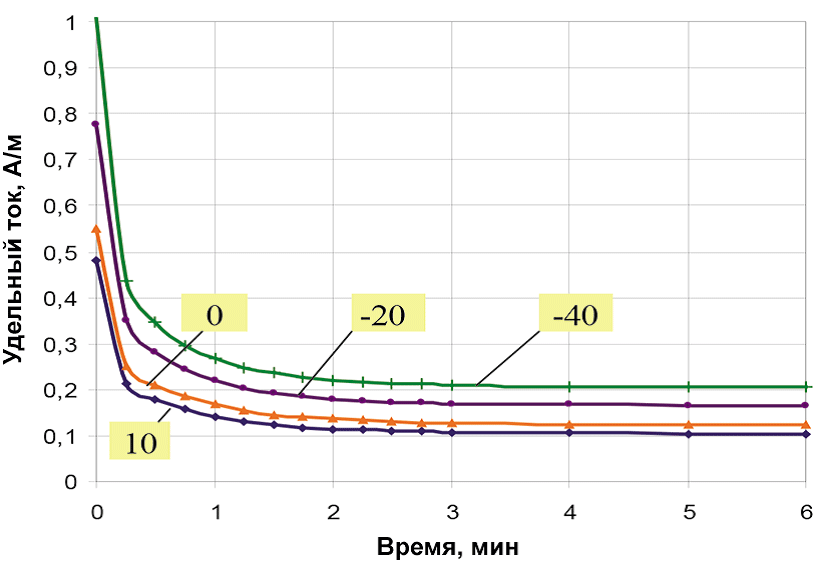
In addition to the steady-state power values, inrush current coefficients have been determined for all cables, knowledge of which will help in the design of heating systems using self-regulating cables. The average values of starting and steady-state currents and the values of Kpt (starting current coefficient) are given in the following table.
Main conclusions from these studies:
- The lower the temperature, the higher the starting current.
- For some cable types, the inrush current can be more than six times the steady-state current.
- As the temperature decreases, the value of the steady-state current increases.
From the accompanying table it can be concluded that the starting current at -20° Celsius is much greater than the operating current at the maintained temperature. The fact is that self-regulating cables are characterized by high inrush current coefficients. For normal operation of the power subsystem, C series machines must be used, and the length of the section should not be more than permissible for the given cold start temperature. Relevant recommendations are given in the technical descriptions.
To reduce the values of inrush currents and simultaneously reduce the ratings of circuit breakers and cross-sections of supply power cables, it is recommended to use specialized control devices for the electrical heating system.
Cross-section of current-carrying conductor, square millimeters
The length of the heating section directly depends on the cross-sectional area of the current-carrying conductor. The use of a cable with a large cross-section of the current-carrying core will make it possible to increase the length of the heating section, reduce the number of heating sections for heating pipelines of significant length and, accordingly, reduce the number of auxiliary electrical installation products (junction boxes, power cables, etc.), i.e. save on materials and installation work.
Maximum operating temperature, degrees Celsius
This temperature should not be confused with the heating temperature of the cable during the process of somoregulation. The fact is that the self-regulating cable:
- Firstly, it heats up unevenly along the entire length, depending on the unevenness of the transfer of thermal energy to the heated surface;
- Secondly, the temperature distribution in the semiconducting matrix itself is very uneven. A diagram of this process is presented in the following figure.
Accordingly, the maximum operating temperature of a self-regulating cable is the maximum possible temperature of the technological process, or otherwise of the heated surface, which the consumer should not allow to be exceeded during operation. If, for example, the maximum operating temperature of the cable is 200 °C, then the design of the heating control subsystem must ensure that the heated surface temperature does not exceed the specified temperature when the cable is in the on state. When switched off, the cable may be briefly exposed to temperatures of 250 °C. However, this exposure in total should not exceed 1,000 hours.
Exceeding the specified values will lead to rapid degradation of the semiconducting matrix and a partial (sometimes complete) reduction in the heat-generating capacity of the cable, resulting in inefficient operation of the entire electrical heating system and excessive energy consumption.
Minimum ambient temperature, degrees Celsius
The minimum ambient temperature is the minimum temperature at which the product can still be used. Considering this technical characteristic of a self-regulating cable, you can notice a very interesting point. In technical documentation, and sometimes in certificates of conformity, this temperature is not indicated by manufacturers. Or -40 °C is indicated, which is completely insufficient for projects located in Siberia and the far north. For a small number of manufacturers, the minimum ambient temperature is the required -55/-60 °C, but the tables for calculating the maximum length of the heated circuit are compiled for a minimum temperature of -40 °C. Particular attention should be paid to this point when choosing a manufacturer, model of a self-regulating heating cable and control subsystem.
Power window – deviation of the released power from the nominal value, expressed in %
Self-regulating cables are produced with some deviation in power from the nominal value. This spread can be up to +/-30% of the nominal value. For obvious reasons, many manufacturers do not indicate this technical specification in their documentation. For the consumer, the use of a cable with a wide power window will mean either excessive consumption of the heating cable at the design stage, or excessive consumption of electricity at the operating stage of the electric heating system.
How to check a heated floor if it is not working - ways to check an electric heated floor
Design and arrangement of electrical cables Malfunctions in the floor heating system - why it does not work Methods of detecting faults - how to check correctly Checking the resistance of the sensor with a multimeter How to diagnose a thermostat How to check the floor system Checking the functionality of the temperature controller Measuring resistance How to ring a warm electric floor
Like other electrical systems, underfloor heating can fail, leaving the room cold. In this case, a careful check of the heated floor is required in order to detect a malfunction. In addition, before pouring the cement screed and installing the finishing coating, it is necessary to determine its suitability for work.
It is especially important to install such a floor for the first floors of private households or for apartments located above basements. This underfloor heating system helps make your home comfortable and cozy. How to check a heated floor if such a need arises?
Checking the sensor resistance with a multimeter
If the floor is in good working order, but does not function, then the cause of the malfunction lies elsewhere. There is a method for checking a heated floor sensor with a multimeter, since the device is a resistor, which means it has its own resistance.
True, the multimeter readings largely depend on the floor temperature. At a temperature of 5 degrees, it will show 22 kOhm, and at 40C - only 6 kOhm. In general, the resistance of the heated floor sensor should correspond to the factory setting. When it differs from the declared value by more than 5 kOhm or is equal to zero, then the sensor is broken and should be replaced.
How can I replace the temperature sensor?
The temperature sensor used in thermostats for heated floors is a thermistor with a negative TCR (temperature coefficient of electrical resistance). This means that when heated, the resistance of the sensor decreases.
The second parameter required to select a temperature sensor is the resistance value under normal conditions, at 20°. The resistor value is usually indicated on the thermostat body next to the temperature sensor connection terminals or in the product data sheet.
To select a temperature sensor, this data is quite sufficient. The only thing that is difficult to find out and select is the TKS characteristic, that is, the change in the resistance value of the temperature sensor due to changes in ambient temperature.
But this is not a critical parameter; anyway, the temperature on the thermostat is set experimentally. After all, the temperature sensor is installed in the floor and the set temperature on the thermostat sets the floor heating temperature, and not the room temperature.
How to determine the resistance of a temperature sensor
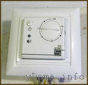
The temperature sensor of the SPYHEAT ETL-308B thermostat has failed. Its technical characteristics were unknown. They had to be determined experimentally.
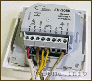
To do this, external circuits were connected to the thermostat, in accordance with the diagram printed on its body - supply voltage was applied, an incandescent light bulb was connected instead of heating elements, and a variable resistance was connected instead of a temperature sensor.
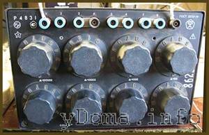
I had a resistance magazine available, so I decided to use it for calibration. The resistance magazine is a box in which high-precision resistances are placed and there are switches with which you can set the desired value.
Consistently setting the regulator knob to positions from 20° to 30° and changing the resistance value with the knobs in the resistance magazine until the thermostat operates, I built a sign.
Dependence of the thermostat response on the resistance value of the temperature sensor
| Temperature set on the thermostat, °C | Turn-on resistance, kOhm | Turn-off resistance, kOhm |
| 20 | 16 | 14 |
| 25 | 10 | 12 |
| 30 | 8 | 9 |
| 35 | 6 | 7 |
Don't miss: Electricity and heating consumption: do you know what uses the most energy in your home?
Based on the data in the table, for this heated floor thermostat, a thermistor with a negative TCR of 10 kOhm is suitable as a temperature sensor. The resistance value of the resistor when turning the light bulb on and off turned out to be different due to hysteresis in the thermostat itself. This is necessary so that the heating element of the warm floor turns on less often.
Determining the temperature sensor rating can also be done using a 47 kOhm variable resistor. You just have to disconnect the thermostat from the network every time after turning the light bulb on and off and measure the resistor resistance with a multimeter.
You can do without measurements. It is enough to have several constant resistors with values ranging from 10, 15, 20 and 30 kOhm. Resistors are connected in turn instead of the temperature sensor. By rotating the thermostat knob, you need to determine which resistor the light bulb will turn off and on at a temperature of about 20°C.
Thermistor selection
You could buy it ready-made, but to do this you had to place an order online and wait for delivery. In addition, the price of the issue reached 20% of the cost of the thermostat itself.
Therefore, it was decided to make a temperature sensor from available thermistors. There was a thermistor with a nominal value of 10 kOhm with a negative negative TKS type MMT-4. I decided to use it for repairs.
For connection there was a piece of wire with which the failed temperature sensor was connected. In principle, any wire can be used to connect the sensor, as long as it can withstand a temperature of at least 100°C. To check, the ends of the wires were stripped and wound onto the thermal resistance terminals.

Next, the thermistor was located in close proximity to the incandescent light bulb connected to the terminals for connecting the heating element of the heated floor. Supply voltage was applied to the thermostat.
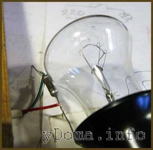
After a few minutes, the light bulb heated the thermistor, its resistance decreased, and the thermostat turned off the voltage supply to the light bulb. When the thermistor cooled down, the light came on again, and this continued ad infinitum with a period of several minutes.
After checking the operation of the heated floor thermostat, wires were soldered to the MMT-4 thermistor with soft solder and pieces of insulating tube were put on the soldering points.
For reliability, you can put a heat-shrinkable insulating tube on the thermistor. A homemade temperature sensor was installed during the installation of a heated floor and showed stable operation.
As you can see, even without experience in repairing electrical appliances, you can repair a thermostat for a heated floor with your own hands at home, including making a temperature sensor from a standard thermistor.
Attention, the electrical circuits of thermostats are galvanically connected to the phase of the electrical network. Touching exposed parts of a circuit connected to an electrical outlet may result in electric shock.
Malfunctions in the floor heating system - why it doesn’t work
It happens that after the installation is completed and everything is connected, the heated floor does not work - how to check why? If there is no heating, it means that an error was made during the installation process or that unsuitable equipment was used.
Before checking the serviceability of the heated floor, it would not hurt to find out about the main errors that occur in its elements:
- Thermostat. Malfunctions of the heated floor thermostat occur as a result of the failure of the capacitor or relay. Since its repair is expensive, it is much easier to replace the device with a new product. The main thing is to find out which company made it. Both the temperature sensor and the thermostat must be from the same manufacturer. Sometimes it is not clear why a warm floor does not heat well, but as a result it turns out that the thermostat is simply not configured correctly or is not working correctly.
- Thermal sensor. If necessary, it can be easily replaced. Depending on the quality, this device can work for both a long and short time. The service life is affected by correct installation. To make sure it is working, you need to know how to check the heated floor temperature sensor. This device must be placed inside a corrugated tube and installed in a certain place and at a specific angle in relation to the wires.
- Cable. It only deteriorates if installed incorrectly. Its most vulnerable part is the coupling.
In order to less often solve the problem of how to check an electric heated floor for malfunction, and not often have to repair it, you should buy equipment from time-tested manufacturers.