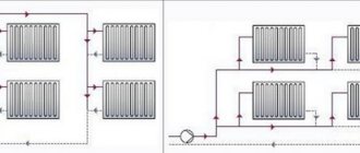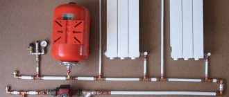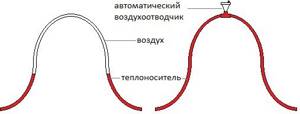
If the pipe slopes in the system are correctly designed, then all the air will be released through the open expansion tank, which is located at the top point of the heating circuit. There can be several reasons for an air lock:
- After repairs, air remained in the heating radiators;
- Incorrect (too fast) filling of the system at startup;
- The circuit is filled with water through an expansion tank;
- When heated, air begins to be released from the water, which was previously in a dissolved state;
- When filling the circuit, water was supplied from above.
The consequences are not difficult to predict - stopping circulation, cold batteries, rapid corrosion of the internal surface of system elements. To avoid this, it is enough to install manual air vents on all radiators - Mayevsky taps.
Causes and consequences of air locks in a closed heating system with forced circulation
The reasons are the same as for an open system, plus:
- A loose circulation pump impeller can “grab” air during operation;
- If hot water is supplied to the expansion tank from above, then air can enter the system through cracks or breaks in the tank membrane.
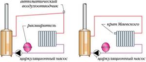
An air lock in a closed circuit will lead to increased pressure in the system and activation of the safety valve. The valve will bleed water over and over again until the boiler burns out or the heating pipes rupture. Therefore, security requirements for closed systems are much stricter. In particular, for air release, the closed circuit is equipped not only with manual Mayevsky valves, but also with automatic air vents. One of these automatic valves is included in the safety group. The group is placed on the water supply, immediately after the boiler.
Important! A leaky pipeline or radiator cannot cause an air lock. A working system, whether closed or open, is under pressure. The air will never go towards higher pressure - this contradicts all the laws of physics.
Modernization of the circulation system
Instant access to hot water in the circulation system is only possible if it is constantly heated, which is certainly associated with certain energy costs. However, these costs are less than when we simply flush the cooled water down the drain. However, it is possible to make the circulation system even more economical.
Recently, experts have begun to use new thermostatic balancing valves
(photo on the right), which calibrate the flow of such a cross-section that will ensure minimal water circulation, but while maintaining the specified temperature in the circuit. As the water cools, the valve increases flow capacity. If the temperature increases above a predetermined level, the valve closes, thus ensuring optimal circulation.
Such valves allow you to set the water temperature in the system within 40-60°C. Previously, throttle flanges or pre-set control valves were used for this. These devices are not automatic and therefore require regular adjustment. New thermostatic valves themselves determine the required distribution of water depending on the prevailing conditions, for example, when actively dispensing water from several taps. This makes it possible to ensure optimal water distribution and slightly reduce energy costs. In addition, thermostatic valves allow you to maintain different water temperatures in the circuits. So, with their help, you can make sure that hotter water flows into the kitchen than into the bathroom, where there is no need to supply water hotter than 45°C.
DHW with circulation and thermostatic valve
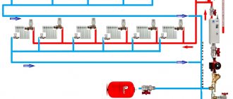
. A simple circulation circuit with a new generation thermostatic valve consists of a hot water source (boiler, storage water heater), a circulation pump, a thermostatic valve, pipes and tapping points. Hot water from the boiler enters the circulation circuit. The thermostatic valve is installed on the return pipe after the last water draw-off point, but before the circulation pump, which is located immediately before the “return” entrance to the boiler. If the system consists of several hot water circuits, then they are connected in parallel, i.e. depart from the supply pipe and return through thermostatic valves to a common return pipe, which, passing through a circulation pump, is connected to the boiler.
Maintaining the optimal temperature in the circulation circuits can also be ensured by circulation pumps, the operation of which is controlled by a thermostat. When the water temperature in the circulation circuit reaches a predetermined level, the thermostat turns off the pump and turns it on when the water temperature drops a few degrees.
The pump can also be controlled by a programmable timer, and this scheme is quite common. Its advantage is that circulation in the DHW circuit occurs only during the period of its use. For example, the pump can be turned off at night when everyone in the house is sleeping. However, it makes sense to choose this option if the family lives according to a certain established regime, which, however, is not uncommon. Energy savings in this case are the highest. Typically, timer systems also allow manual pump control. For example, if on some holiday hot water will be used at night, then it is enough to turn on the pump and circulation will take place in continuous mode.
Manual control of the pump is, in principle, very reliable, but there are inconveniences, since you have to turn on the pump in advance and then remember to turn it off. For manual control, it is recommended to additionally equip the pump switch with a shutdown timer. However, even in this case, situations will often arise when one of the residents forgets to turn on the pump and drains all the water from the pipes.
Methods for removing air from a heating system
There are two ways to get rid of air pockets in a heating pipeline; the choice of one of them depends on the type of wiring of the heating circuit. If the wiring is upper and the coolant circulation is natural, then the easiest way to remove air is through an expansion tank, which is installed at the highest point of the system.
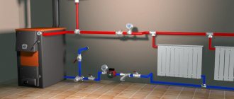
Air vent location diagram
If the pipe distribution is bottom and the coolant circulation is forced, then the air entering the system accumulates in the air collector, from where it can be easily removed using special air vent valves. In this case, the supply pipe is installed with a rise to the highest point of the circuit, and the return pipe is mounted with a downward slope. This ensures unimpeded drainage of water from the heating system should such a need arise.
Video
Automatic vent for hot water supply
Today we have to find out why we need to install an air vent in the water supply system. In addition, we will find out in which part of the water supply circuit it can be installed, what kind of air vents can be used there, and how to solve the problem of air in the water supply without an air vent. Let's get started.
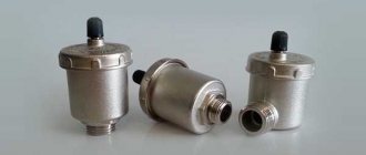
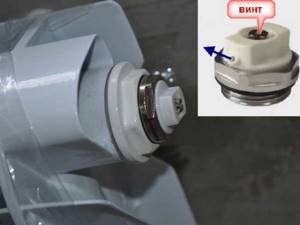
Valve for releasing air from the water supply. Operating principle of automatic air vent
It is easy to guess that this type of air release valve operates without human intervention. The element is a vertical barrel made of brass with a threaded connection G ½ “(DN 15), where a plastic float is placed. The latter is connected by a lever to a spring-loaded air release valve mounted in the lid.
For reference. Automated air vents (in common parlance - auto vents, vents or vents) are produced with two types of external connecting threads - ½" and 3/8". But in the post-Soviet space, products with half-inch threads are usually used; 3/8 is extremely rare.
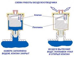
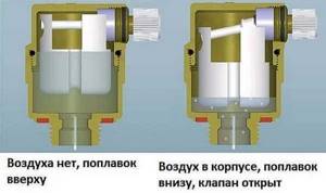
The operating principle of the automatic air vent is as follows:
- In operating mode, the chamber inside the housing is filled with water, pressing the float upward. The spring loaded air valve is closed.
- As air accumulates in the upper zone of the chamber, the coolant level decreases and the float begins to descend.
- When the level drops to a critical value, the weight of the float overcomes the elasticity of the spring and the valve opens, bleeding air outward.
- Due to excess pressure in the heating system, water will displace all the air from the chamber of the device, take its place and raise the float again. The valve will close.
Cavitation as a cause
Before you start clarifying the issue, it is important to know: pumps are installed depending on the diameter of the well! For sizes of 100 mm, a submersible pump is suitable; smaller diameters require a circular or plunger pump. What is cavitation? This is a violation of the continuity of liquid flow, otherwise it is the filling of water with bubbles
Cavitation occurs in those areas where the pressure drop reaches a critical level. The process is accompanied by the formation of voids in the flow, the release of air bubbles that appear as a result of vapors and gases released from the liquid. Being in an area of reduced pressure, bubbles can increase and collect into large empty cavities, which are carried away by the flow of liquid and, in the presence of high pressure, are destroyed without a trace, and in the conditions of an ordinary domestic well, they often remain and it turns out that the pump pumps air bubbles from the wells not producing the required volume of water
What is cavitation? This is a violation of the continuity of the fluid flow, otherwise it is the filling of water with bubbles. Cavitation occurs in those areas where the pressure drop reaches a critical level. The process is accompanied by the formation of voids in the flow, the release of air bubbles that appear as a result of vapors and gases released from the liquid. Being in an area of reduced pressure, bubbles can increase and collect into large empty cavities, which are carried away by the flow of liquid and, in the presence of high pressure, are destroyed without a trace, and in the conditions of an ordinary domestic well, they often remain and it turns out that the pump pumps air bubbles from the wells without producing the required volume of water.
Identifying a cavitation zone is sometimes impossible due to the lack of special instruments, but it is important to know that such a zone may be unstable. If the deficiency is not eliminated, the consequences can be devastating: vibration, dynamic effects on the flow - all this leads to breakdown of the pumps, because each device is characterized by a specified value of the cavitation reserve
Otherwise, the pump has a minimum pressure within which water entering the device retains its density properties. When pressure changes, cavities and air voids are inevitable. Therefore, the selection of a pump should be carried out depending on the volume of water needed to meet economic and domestic needs.
Installing air release valves
To remove air from heating, air vents are installed on radiators - manual and automatic air valves. They are called differently: bleeder, air vent, bleeder or air valve, air vent, etc. The essence does not change from this.
Mayevsky air valve
This is a small device for manually bleeding air from heating radiators. It is installed in the upper free radiator manifold. There are different diameters for different collector sections.
Manual air vent - Mayevsky tap
It is a metal disk with a conical through hole. This hole is closed with a cone-shaped screw. By unscrewing the screw a few turns, we allow the air to escape from the radiator.
To facilitate air outlet, an additional hole was made perpendicular to the main channel. The air actually comes out through it. When deflating using a Mayevsky tap, point this hole upward. After this you can unscrew the screw. Unscrew it a few turns, but do not unscrew it too much. After the hissing stops, return the screw to its original position and move on to the next radiator.
When starting the system, it may be necessary to bypass all the air collectors several times until air stops escaping altogether. After this, the radiators should heat up evenly.
Automatic air release valve
These small devices are installed both on radiators and at other points in the system. They differ in that they allow you to bleed air in the heating system automatically. To understand the principle of operation, consider the structure of one of the automatic air valves.
The operating principle of the automatic release is as follows:
When air enters the chamber, the coolant is forced out of the housing and the float lowers.
Operating principle of automatic air release valve
Various designs of automatic air valves operate on this principle. They can be straight or angular. They are placed at the highest points of the system and are present in the security group. They can be installed in identified problem areas - where the pipeline has an incorrect slope, which is why air accumulates there.
Instead of Mayevsky's manual taps, you can install an automatic drain for radiators. It is only slightly larger in size, but works automatically.
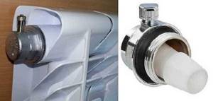
Automatic air release valve
Cleaning from salts
The main problem with automatic valves for venting air from the heating system is that the air outlet hole is often overgrown with salt crystals. In this case, either the air does not come out or the valve begins to “cry”. In any case, you need to remove it and clean it.
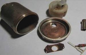
Automatic air vent disassembled
So that this can be done without stopping the heating, automatic air valves are installed in pairs with non-return valves. The check valve is installed first, followed by the air valve. If necessary, the automatic air collector for the heating system is simply unscrewed, disassembled (unscrew the lid), cleaned and reassembled. After this, the device is again ready to bleed air from the heating system.
Methods for purifying water from iron using a filter and aerator
The choice of the type of water deferrization plant with aeration depends on the type of metals contained. Iron may be present in tap water in the following forms:
- Fe(II) - dissolved divalent. It does not change the color of the liquid and is not visually noticeable.
- Fe(III) is insoluble trivalent. Forms a precipitate and gives a “rusty” color.
- Colloidal - tiny solid particles that create turbidity in water.
- Organic - part of organic pollutants.
- Bacterial - forms an iridescent film on the surface of the liquid, as well as a silty sediment at the bottom.
Ferric iron is the easiest to remove. It precipitates and is easily filtered. The remaining forms of iron must first be converted to the filterable form Fe(III). In this case, aeration is used to remove iron from the water. Manganese is found in raw water from underground sources in the form of Mn(II). Its concentration in untreated water can reach 0.1%. The divalent form of the element is partially dissolved and can form a precipitate when the liquid is heated very strongly. To purify water from manganese, it is converted into a trivalent or tetravalent form - it is converted into insoluble compounds (metal oxides, hydroxides, acid salts). This also produces a precipitate that can be caught by filtration.
Iron removal filters
Filtration plants for removing iron and manganese from water are divided into industrial and domestic. They differ in the degree of purification, productivity, type of action, cost, and complexity of maintenance.
By design, there are three categories of iron removal plants:
- Reagent filters . Here, the purified water passes through a granular filler that has a high sorption capacity. In this case, dissolved metal salts are converted into an insoluble form, which settles on the filter granules. To catalyze the process, potassium permanganate, chlorine dioxide, and sodium hypochlorite are used.
- Reagent-free filters . The housing of such a filter is filled with an active catalytic absorber. Previously, when passing through the aerator, oxidation of divalent iron to trivalent iron occurs, followed by precipitation of solid rust particles directly on the deferrization filter. Insoluble flakes settle on the sorbent and are washed off with a stream of water when washing the filter. For an iron removal plant to operate in this manner, aeration is required.
- Filters for complex water purification from iron and hardness . These are complex installations that include several stages of cleaning. They remove iron, manganese, ammonium, and harmful organic compounds from water. They also soften and clarify water. Multifunctional units are compact, economical, and have a simple regeneration system.
Reagent deferrization is used to purify water with low pH and high concentrations of iron, manganese, and hydrogen sulfide. To regenerate the filter material, backwash the filler with a special solution; the restoration process takes approximately 1.5 hours.
Reagent-free aeration units have a long service life, and their regeneration does not require the consumption of reagents. These filters trap iron, manganese, and dissolved corrosive gases. These are highly efficient units widely used in various industries.
Deferrization of water by aeration
Aeration of water to remove iron is a process of intensive saturation of water with oxygen, as a result of which the iron contained in it is oxidized to an insoluble form. According to the method of aerating water from iron, installations are:
- Pressure . Air is forced by a high-pressure air compressor into the water stream at the inlet of the aeration column or pipe. Excess air is discharged into a separator or air vent, and oxygen-enriched water enters the filter column with catalytic media. Here the final oxidation of iron occurs, as well as the precipitation of undissolved metal and suspended particles. Pressure aerators for iron removal are used even with high water flow rates and high iron content.
- Non-pressure . Such aeration and water deferrization stations operate at low environmental pressures. Because of this, gravity aeration with iron removal is usually used for low water flow rates and low iron concentrations. The liquid is supplied by a water pump through spray nozzles into a special open container. The interaction of iron and oxygen is ensured by the ejection and suffocation of water. Excess air is released through the air valve, and oxidized insoluble iron is deposited in the filter media of the installation.
- Electrochemical oxidation of iron by aeration . Aeration occurs through the use of an electrochemical reaction that converts different types of energy. These are modern, productive installations for water deferrization by aeration, characterized by small dimensions, low noise levels and ease of operation. Suitable for purifying water with high iron content.
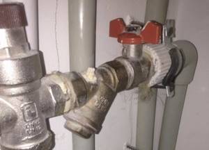
Features of installing an air vent in a private house
An air vent designed for heating communications in a private home must be installed strictly in a vertical position. For installation work you will need a threaded tee, FUM tape, and an open-end wrench.
The installation process is carried out in stages:
- Tee fastening. You will need a piece of pipe onto which a tee is fixed by soldering, glue or simple shrinkage.
- Preliminary check of the location of the vent at the highest point of the equipment. The device connection must have an upward direction.
- Installing the shut-off valve on the hexagon of the device using an open-end wrench.
- Connect the automatic air vent so that the protective cap with nipple faces upward.
- Screw the cap tightly to prevent debris from accumulating.
- Checking the tilt of the device (for radiator models). The battery section with the drain rises slightly.
After installation, the devices do not need to be adjusted - they will bleed air automatically.
It is better to install the air vent with a shut-off valve - this makes it easier to remove it for repair or replacement.
Features of a multi-stage scheme
The multi-stage deaeration scheme provides for the installation of automatic devices along the entire line. Connecting the vents in this way allows you to locally and simultaneously remove air pockets. The automatic device is placed in the zone of rotation, formation of a loop. To extend the service life of the valve, an additional filter is installed. Once assembled, the system operates with the radiator hot at the bottom but cold at the top.
In two-story houses, installation of diverter devices must be carried out on the top floor.
A corner, straight or radiator vent is suitable for the heating main of an apartment building or private building. The automatic device is simple, reliable and maintainable. After installing it, the owner does not have to waste time monitoring the system and manually bleeding air.
About hot water supply
First, let's find out why airing of the water supply system occurs and how it interferes. Let's start from afar.
The cold water supply of an apartment building or private building always has a dead-end distribution: the bottling goes into risers, they branch into connections, and the connections end with taps of plumbing fixtures. Water moves in a dead-end circuit only due to water intake.
Dead-end DHW circuit
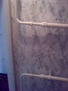
Until about the 70s of the last century, hot water supply systems (DHW) in all houses under construction were organized in the same way.
Dead-end hot water distribution
However, this wiring has two serious drawbacks:
- Having opened the hot water tap, the homeowner is forced to wait for several minutes for it to heat up. The wait is especially long at night and in the mornings, when in the absence of water supply the risers and hot water outlets cool down. This is not only inconvenient, but also contributes to unreasonably high water consumption;
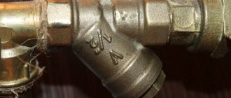
Please note: when recording hot water consumption using a mechanical water meter, you are forced to pay for the entire volume passing through it. In fact, a significant part of this volume does not meet the requirements of current operational standards: the DHW temperature must be within the range of +50 - +75°C.
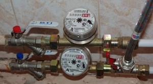
The mechanical meter in the photo records water flow through the hot water pipeline, regardless of its temperature
- Heating of bathrooms and combined bathrooms in apartment buildings is provided by a heated towel rail powered by a hot water supply system. It is clear that in the absence of water intake in the dead-end system it will cool down. For the apartment owner, this means dampness and cold in the bathroom, and in the long term, a greater likelihood of fungal damage to the walls.
The heated towel rail is mounted in the gap of the hot water supply line, and heats up only when drawing water
Circulation scheme
Since the late 70s - early 80s, hot water supply in new buildings gradually began to become circulating.
- Two hot water supply outlets are laid in the basement or subfloor of the house;
- Each bottling has an independent insertion into the elevator unit;
- The hot water supply risers are connected alternately to both dispensers and are connected by jumpers on the top floor or in the attic. From 2 to 7 risers can be combined into groups connected by circulation jumpers.
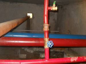
There are two hot water dispensers in the basement
Please note: installing lintels in the attic is extremely unwise in cold climates. The author encountered it in the Far East: at a temperature in a cold attic of -20 - -30 degrees, stopping circulation in the hot water system (for example, during an emergency shutdown of hot water) causes the water in the jumper to freeze within an hour.
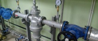
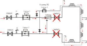
In order for water to continuously circulate through risers and bottlings, a pressure difference must be created between them. In the elevator unit and further, in the heating circuit powered from it, circulation is ensured by the pressure difference between the supply and return pipelines of the heating main. The obvious way to supply hot water is between the supply and return connections.
However, in this case, an unpleasant surprise awaits us: the bypass between the pipeline threads will catastrophically reduce the drop in the water jet elevator, preventing the heating from operating.
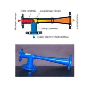
Appearance and operating principle of the water jet elevator
The problem can be solved simply and elegantly:
- The hot water supply cuts into the supply to the elevator at two points. Each of the inserts is equipped with shut-off valves;
- The flange between the inserts is equipped with a retaining washer. This is the name of a steel pancake in which a hole is drilled in the center with a diameter 1 mm larger than the diameter of the nozzle. During normal operation of the elevator and the associated movement of water along the supply line, such a washer creates a difference between the tie-ins of approximately 1 meter of water column (0.1 atmosphere);
- Exactly the same two tie-ins with the same retaining washer are mounted on the return pipeline.
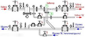
The simplest elevator unit with hot water circulation and two taps into the return pipeline
An elevator with hot water circulation taps has three operating modes:
- Hot water circulates from supply to supply . This scheme is used in spring and autumn, at a relatively low (up to 80 degrees) coolant temperature in a straight line of the heating main;
- From return to return. DHW switches to this mode in winter, when the supply temperature exceeds 80°C;
- From supply to return. So the hot water supply system with circulation is powered in the summer, when the heating is turned off, and the difference between the threads of the heating main is minimal or absent.
Air vent - how does it work?
When using the system, air gradually accumulates inside the automatic device and the float lowers. Together with him, he pulls the lever and the drain valve to the bottom. This leads to a smooth release of air to the outside. Now the float gradually rises, closing the drain valve. This way, only water remains inside the device. If air forms again, it again flows to the upper part of the system, where the automatic air vent is located. Its next accumulation and discharge occurs.
The Mayevsky valve is designed to discharge gas bubbles manually. To open the valve, you need to turn the plastic handle (if there is one) or twist it with a key or screwdriver. You should stop when hissing sounds appear, which serve as a signal that air is leaving the heating device.
In what cases are deferrization and aeration systems used?
An iron removal filter in combination with aeration is used for water from a well or well. To choose the right aeration and iron removal station, you need to know the standards of iron and manganese in water.
Iron standards
The quality of water used for drinking or cooking is regulated by sanitary standards SanPiN 2.1.4.1074-01. Here the hygienic requirements for drinking water are specified, indicating the maximum permissible concentrations (MAC) of the impurities contained.
According to the standard, the maximum permissible iron content in water from centralized water supply networks in populated areas is 0.3 mg/l. But this is a limiting indicator; the presence of iron can be noticed at a much lower concentration. The main signs of high Fe content:
- metallic taste of water;
- unpleasant pungent odor;
- turbidity, “rusty” tint of water - normally the liquid should be colorless;
- loss of loose sediment during prolonged settling of initially clear water;
- reddish coating on water storage tanks, rust stains on plumbing fixtures.
The aeration column is used precisely to oxidize iron and precipitate it. The characteristic “iron” taste and smell appear already at an iron concentration of 1.0-1.5 ml/g. With prolonged use of such water, a feeling of dryness and tightness of the skin occurs, and dermatitis and allergic reactions may occur. And a high concentration of iron (over 0.3 mg/l) leads to the failure of plumbing and water-consuming equipment.
Manganese standards
An iron remover with aeration, together with iron, reduces the concentration of manganese. The maximum permissible concentration of manganese in water according to SanPiN 2.1.4.1074-01 is 0.1 mg/l, but in developed countries this figure does not exceed 0.05 mg/l. Excessive presence of manganese can be noticed by the yellowish tint of the water and an unpleasant astringent taste.
Drinking water supersaturated with manganese leads to chronic liver diseases and negatively affects the condition of the skeletal system, kidneys, intestines, and brain. Poisoning with this metal leads to serious disorders of the nervous system. The manganese content in process water causes the deposition of dense foam on the inner surface of pipes and reduces the heat transfer coefficient of heat exchangers. To prevent chronic diseases and equipment breakdowns, we recommend a water deferrization complex with aeration.
Where are air vents installed?
Given how the automatic air vent works, the device is designed to be installed
:
- At the highest points of heating circuits (top of vertical risers, etc.), where air bubbles from the coolant tend to enter.
- At the ends of dead-end pipeline branches.
- As part of the safety group for boiler piping (primarily solid fuel) in a closed-type heating system. The automatic air vent is mounted on the manifold along with a pressure gauge and an emergency valve. The device helps to bleed air when the water jacket of a boiler unit is filled with coolant or quickly drain water from it when emptying a heat generator cut off from the heating circuit.
- On the circulation pump in order to improve its operation, if the design of the unit provides for the installation of a device for releasing air. Pumping airy coolant impairs the operation of the pump, an air lock causes it to stop, and the impeller and bearings wear out faster. The air vent also removes steam from the overheated coolant.
- On the pipeline of a working system if an area is detected where air constantly accumulates (this happens, in particular, if the angle of inclination of the pipes is not observed).
- For heating devices.
Risers and liners
Risers are responsible for the vertical distribution of water in apartments located one above the other. The connections perform the function of distributing liquid through taps and other plumbing fixtures inside the apartment.
In apartments, serial (tee) wiring is traditionally used. The collector type is more material-intensive and requires hidden installation of connections, which greatly complicates their further maintenance.
DHW systems are divided into two types:
- centralized,
- local (decentralized).
In centralized systems, a heating installation in a central heating point (centralized heating point) can serve one or more buildings within a microdistrict or village. Centralized circuits are designed and installed with circulation pipelines for uninterrupted supply of hot water. Without them, in the absence of water supply in the supply pipelines, the water cools down, and the consumer is forced to drain it, which leads to excessive water consumption on the meter. In addition, heated towel rails are installed, which cannot work in the absence of circulation.
Decentralized (local) hot water supply is used in cases where the construction of a centralized scheme is not economically profitable: with a low density of heat loads in rural settlements, etc.
DHW schemes are:
- With a dead-end pipeline, where, with low consumption or no water withdrawal, the water quickly cools down. This scheme is used in low-rise residential buildings with a short network, bath and laundry plants.
- With circulation risers. Similar schemes are used in multi-storey residential buildings and hotel complexes.