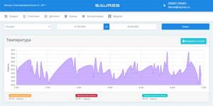
Convenient temperature monitoring
Live data and customizable temperature graphs are available through any web browser and the SAURES mobile app. We store data for a whole year. If you need to store longer, there is a paid option for this.
A demonstration room of the system with temperature sensors is available free of charge and does not require registration.
Test it now!
Go to your account
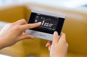
Why do you need to control your heating system?
The boiler control technique via GSM is carried out using a special device called a GSM module. The device has the form of a compact unit that can be easily installed on a wall or mounted on a DIN rail. Next, the boiler is controlled via the phone (by setting up an SMS in the required format) or using the Internet, then a special application is installed for this purpose.
As a result, it becomes possible to obtain the following benefits:
- the ability to create the required temperature regime in the house, regardless of the current time of year and while being in any convenient place;
- remotely prepare comfortable climatic conditions inside the house before visiting, because it is more pleasant to come to a country house if it is heated in advance;
- in winter frosts you will not have to worry about depressurization of the heating system, even if it is not possible to visit the country house immediately;
- receive notifications about current problems while outside the home;
- instantly stop the heating operation in emergency situations;
- use fuel in an economical mode;
- prevent the occurrence of complex consequences in an emergency situation, having the opportunity to turn off the boiler at any moment.
Thanks to GSM control, heating coordination moves to a new level, having the opportunity to influence current events while being (at the same time) away from the operating unit. This option opens up new opportunities for people who spend a lot of time on the road without being able to exercise daily control over the operation of the heating system.
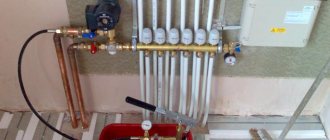
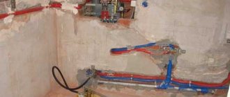
Automatic control of ball valves, relays, thermal heads
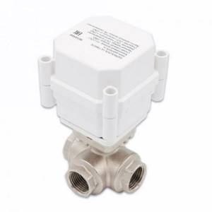
In our system, using Wi-Fi controllers, you can use too high or too low a temperature as an event to control ball valves, relays, and thermal heads.
You can close or open a tap, control a pump or boiler, change the direction of water flow using three-way ball valves, maintain the room temperature by controlling a heating radiator, and much more.
Example scenario: Automatic pressure release in a street pipeline (for example, in an irrigation system) when frost occurs.
Example scenario: Automatic switching of central hot water supply to an electric boiler.
Example scenario: Automatically maintaining the room temperature within a given range using thermal heads.
How to connect?
To connect and install the GSM module yourself, you must use the instructions included in the kit. Installation and startup of the device occurs as follows:
- De-energize the heater.
- Remove the protective casing from the boiler.
- Secure the module mount to the wall.
- Insert a SIM card and battery into the module, if necessary.
- Connect a gsm-based controller to the connector located in the boiler.
- Connect all sensors to the module.
- Connect the device to the network.
- Put on the boiler protective casing.
- Connect the boiler to the electrical network.
It is worth remembering that to work on a SIM card, you need to choose one of the best mobile operators with good signal quality. When the module is connected for the first time, the user needs to send an SMS to the controller’s SIM card with its number.
If the signal is weak, you must install the included antenna
To better understand the connection process, it is recommended to watch a detailed video to avoid mistakes.
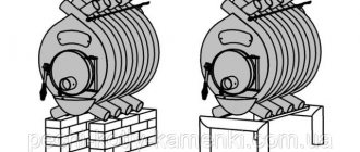
Gsm modules work perfectly with both electric and gas boilers; they can also function with exhaust models. The boiler itself must have an output for connecting the controller. This device helps save energy consumption and greatly simplifies the process of controlling the heating device.
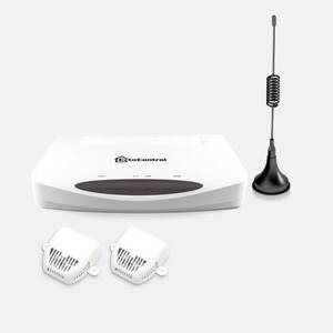
Two wireless technologies: Wi-Fi and NB-IoT
Our line of controllers includes models with Wi-Fi and NB-IoT modules. It's very easy to choose the right one.
- If your facility has a permanent Wi-Fi network, then choose Saures controllers with Wi-Fi.
- If there is no Wi-Fi network at the installation site, but there is NB-IoT network coverage (map on the MTS website), then use NB-IoT controllers.
- If both networks are present, then “choose with your heart”: the old and proven Wi-Fi or the new and advanced NB-IoT.
You can buy controllers for remote measurement of air temperature in our online store and from official dealers.
Go to the store
When purchasing an NB-IoT controller, data traffic for 6 years is already included in the price.

How to choose a GSM module, what should you take into account?
Devices running on the Gsm platform can be purchased both in city stores and on well-known trading platforms such as Aliexpress. Before buying such a module, you should decide what capabilities are expected from it? For example, whether the length of the antenna cable to be connected is important, as well as how many telephone numbers can be used at the same time. When choosing a module, you should consider the following factors:
- number of control zones;
- availability of outputs for connecting sensors of different purposes;
- the ability to expand functionality by updating the device’s firmware;
- the presence of a relay through which feedback is provided;
ability to monitor temperature and send readings to a mobile phone
A good module has adjustable temperature modes and response thresholds.
With its help, you can remotely control the operation of the boiler and make changes to the temperature. A high-quality device will make it possible to change power indicators, and will also instantly send an SMS notification about the activation of emergency sensors.
Do-it-yourself automatic home heating control. Part 1
Multifunctional devices BM8036 and NM8036 manufactured by Master Kit can be used as a central part of a control system for heating, cooling, ventilation, etc.
Based on the NM8036, one of our customers decided to make automatic home heating control and described in detail the process of implementing his idea: “In the article Heating Automation for the Home, I wrote about what kind of automation is needed for a heating system with a water heat accumulator (WTA). Based on the desired algorithm and the operating features of a heating system of this kind, I came to the conclusion that a programmable control unit is needed that performs not only the functions of a thermostat, but also a timer with a calendar. In principle, you can just take an old computer, some Pentium 2, write a program for it that will perform all the desired functions - and that’s the end of the matter. I admit, I still haven’t lost this mood yet. However, I suddenly remembered a company where you can buy a lot of different kits for a wide variety of tasks. This is Master Keith.
But I must say that this company supplies various kits for assembling radio-electronic devices. What is a kit? This is usually a printed circuit board and a set of parts for assembly. True, there are already assembled, ready-made devices. I, in fact, used this service before, collected something... And then, after rummaging quite a bit in its catalog, I discovered a device that, in general, quite meets my requirements. This is a 4-channel timer-thermostat NM8036.
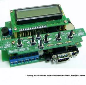
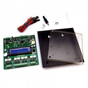
There is also an analogue of such a thermostat in the catalog, but with 8 channels: BM8036.
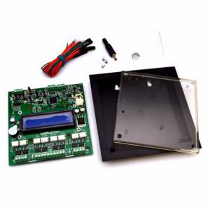
*the device is supplied soldered with installed power switches complete with a housing and 8 temperature sensors
If you take a closer look at both options, then my personal choice is 4-channel. Why? It can easily be expanded to 12 channels. More precisely, both devices can be converted into a 12-channel version. That is, install 12 devices under its control. And this is not my invention, the Master Kit website talks about all this. My choice fell on NM8036, since it is cheaper. However, the use of one or another option depends on the tasks, soldering skills, etc. (for some it will be easier and more convenient to use a ready-made device).
What devices could these be? Well, for example, electric valves of the heating system, circulation pumps, electric heating elements, fans, electrically controlled valves... I was blown away. Valves, fans... So, I’m already estimating that this thermostat will not only control the heating system, but also maintain the optimal storage temperature for vegetables in the basement.
It is worth noting that a huge number of temperature sensors can be connected to the inputs of this device. Digital sensors with high accuracy. And for electronics connoisseurs, there is also the possibility of connecting a couple more analog sensors to the ADC inputs.
But that’s not even the highlight of this unit. Its software core allows you to program the work without knowledge of any programming languages. Everything is at the level of human understanding in Russian. Although, of course, it will probably be difficult for a person far from such things to cope with this. At least not right away, not right away.
But what I especially liked was that this device can be connected to a computer and you can play around with it not using its standard buttons, but from the computer keyboard. View the program, change it, upload new firmware versions... Is it difficult, Master? I don't know, I don't think so. Today the age is such that 12-year-old grandchildren are no longer looking at the buttons on the keyboard. Am I dumber than them, or what? Dude, they won't catch us!
Well, in short, I assembled this device and debugged it. Now there is only one small thing left: to place the temperature sensors in their places and create a program according to the algorithm that I need for the system to work. And this is not at all a pipe dream. Look, Master, read how many people are already using this thermostat. I didn’t make any discovery here, I just found what I needed at an affordable price.
Well, what is required to completely assemble my control unit? I thought about it on my wish list and decided to use all 12 channels at once. Maybe not right away, but the control unit needs to be assembled completely. That's why:
1. Timer-thermostat NM8036 1 pc. 2. Executive relay unit NM4411 3 pcs. 3. Power supply PW1220D 1 pc. 4. Digital temperature sensor DS1822 4 pcs.
I bought all this in an online store. Temperature sensors, in fact, come complete with a timer, there are already 4 of them. But I also took 4 for expansion. They won’t be superfluous. And at a local store I looked at a housing for the control unit, where you can plug all these components.
Master Keith himself does not engage in trading; this is done by various dealer stores, including online stores. There are no supermarkets in my village, so I use online shopping.
Here is the build process
Now let's talk about the assembly and launch of the heating control unit based on the NM8036.
Master Keith has very good instructions for using the kit. There is a link to it on the set description page at the end.
But today I didn’t start the story to repeat these instructions. There are various underwater pebbles and cobblestones that are not mentioned in the instructions, but in my practice I either stumbled upon them, or miraculously avoided them, but I could have stumbled upon them. This is what I will talk about.
I will not tell or show how to solder elements to a printed circuit board. Of course, this is not done with a blowtorch and a certain minimum skill is, of course, highly desirable. The rules here are simple: accuracy and attentiveness, try not to overheat the conclusions and contact pads.
There are diagrams with sets, lists of elements are included, names are written on the elements - have, as they say, eyes and hands. But I want to remind you of one thing: after assembling, cleaning and washing, do not rush to turn it on immediately. Take, Master, a larger magnifying glass and check each soldering most carefully. EVERYONE! So that the circle is even, so that shorting solder snot does not stretch from it to other contacts. The lion's share of malfunctions arises from poor-quality soldering.
Correctly insert the processor (controller) into the socket. This is the largest microcircuit; it has a notch at the end, indicating the beginning of the conclusions. The wiring diagram shows where this notch should point.
Collected? Have you checked? Now check again. Test shot before launch. Shot? Well, cross yourself at the image and poke the power connector. Just keep in mind that if you insert it in the wrong place, the pleasure will be dubious, and the result will not be the same.
Look, near the COM connector there are two smaller connectors - on the right and on the left. The one on the right is a connector for connecting sensors. And the power connector is the one to the left of COM. So, the power connector fits very well into the sensor connector. Be careful, otherwise you risk getting into trouble.
COM connector. For what? To connect to a computer... and more. The controller outputs for controlling loads OUT0, OUT1, OUT2 and OUT3 are connected to the contacts of the same connector (see connector XS1 in the diagram). That is, these 4 outputs can be used directly from this connector.
Not bad, of course, but if you don’t use them here, and use the connector only to connect to a computer, then don’t try to use any cable for the connection. This cable can also have wires soldered to the output contacts. It is unknown how this may end. The instructions say how to unsolder the cable to connect to a computer - do so.
Further. These little blue terminal blocks (XS6 - XS9), to the left of the connectors, don’t need to be installed at all if you intend to use NM4411 sets for control. Moreover, you also don’t have to solder all the elements that are provided in these output stages. Everything that is available on this fragment of the NM8036 circuit (there are 8 more resistors and 4 optocouplers).
These elements are not needed (less rations - a more reliable device). How then to connect the controller outputs to the NM4411 inputs? So, how... directly.
I said that this set has only 4 outputs, to which, accordingly, only 4 loads can be connected. And the software, firmware of the controller can provide operation with 12 loads. In this case, each of them is connected directly to the controller contacts (although, of course, the first 4 can be taken from the COM connector, as standard).
How about directly?
If you look at the NM8036 board from the solder side, it will look something like this picture (click on it to enlarge). The outputs of control channels from 1 to 12 are numbered with corresponding numbers. Two analog inputs (A1 and A2) are also numbered, which are also processed by the new controller firmware.
If, Master, you watched the assembly video, then, of course, you noticed a bundle of wires soldered to the controller pins on the back of the board. Using this cable, I connected the indicated pins to the connector on the additional board.
And there another harness already went from this connector to the NM4411 executive relay boards and two switches, which were connected to the analog inputs of the controller. What are the switches for? I installed them to switch the operating modes of the heating system.
Controlling the heating of a private house with a boiler and a heat accumulator cannot be solved unambiguously. It’s not just a matter of “turning it on and off.” The operation of a boiler to accumulate thermal energy is a separate mode, different from the heat consumption mode. My first switch is to turn on/off the “Boiler” mode, which exactly corresponds to the operation of the boiler.
The second switch in my case turns on the heating of the bath. In standby mode, the temperature in the waiting room, sink and sauna is maintained at 16 degrees. When the heating is turned on, the temperature in the sink rises to 35 degrees.
The mode switch circuit is simple, it is a pair of 1 kohm resistors soldered to the toggle switch. The top resistor in the diagram is connected to pin 10 of the controller (VCC, +5V power supply), and the bottom resistor is connected to pin 11 (GND, common).
It remains to supplement this article with considerations for choosing a case. In my case, the choice of a plastic case, which I found in one of the local electrical goods stores, turned out to be very successful. Some crampedness in it was fully compensated for by a rather appropriate transparent window for placing the NM8036 unit with a display underneath. It also houses the power supply and 3 NM441 control boards of 4 channels each.
The keyboard and mode switches were secured to the inside of the lid. This resulted in a good heating control unit for a private home.
To be continued…"