Ventilation system calculation form
Plot number (see Fig. 2.2)
P
D,
Pa
R values
determined either from special tables or from a nomogram (Figure 3.2) compiled for steel round air ducts with diameter
d
.
The same nomogram can also be used to calculate air ducts of rectangular cross-section a b
, only in this case the value
d
is understood as the equivalent diameter
d
e = 2
ab
/ (
a
+
b
).
The nomogram also shows the values of the dynamic pressure of the air flow corresponding to the density of standard air ( t
= 20 o C; φ = 50%; barometric pressure 101.3 kPa;
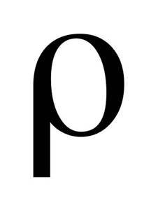
= 1.2 kg/m3). At density
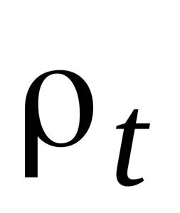
dynamic pressure is equal to the scale reading multiplied by the ratio
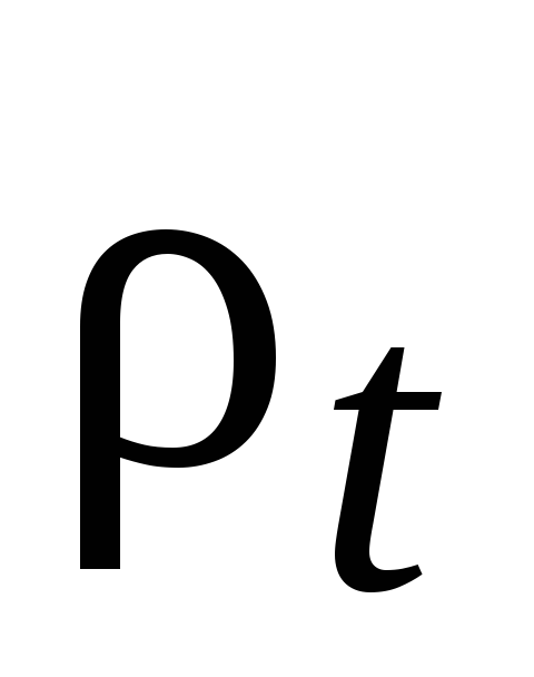
/1,2
Fans are selected according to aerodynamic characteristics, showing the graphical interdependence of their total pressure, flow, rotation speed and peripheral speed of the impeller. These specifications are based on standard air.
It is convenient to select fans using nomograms, which are summary characteristics of fans of one series. Figure 3.3 shows a nomogram for selecting centrifugal fans of the Ts4-70 * series, which are widely used in ventilation systems of agricultural industrial buildings and structures. These fans have high aerodynamic properties and are silent in operation.
From the point corresponding to the found feed value L
c, draw a straight line until it intersects with the ray of the fan number (fan no.) and then vertically to the line of the calculated total pressure
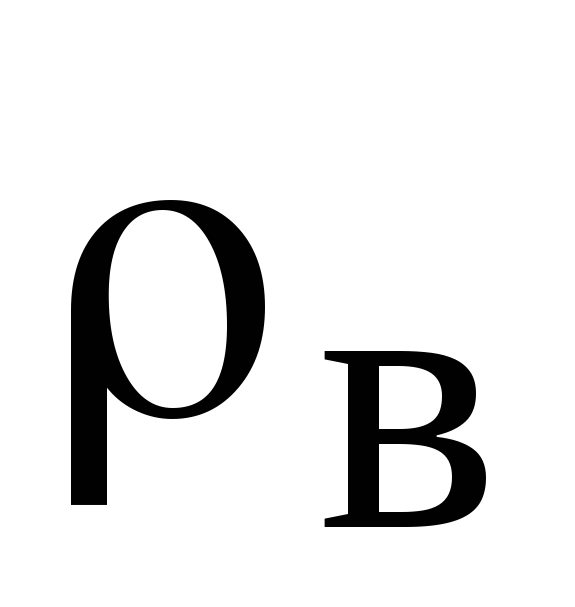
fan
The intersection point corresponds to the fan efficiency
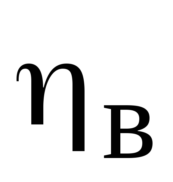
and the value of the dimensionless coefficient
A
, by which the fan rotation speed is calculated (min -1).
The horizontal scale of the nomogram shows the speed of air movement in the fan outlet.
The selection of a fan must be carried out in such a way that its efficiency is not lower than 0.85 of the maximum value.
Required power on the electric motor shaft to drive the fan, kW:
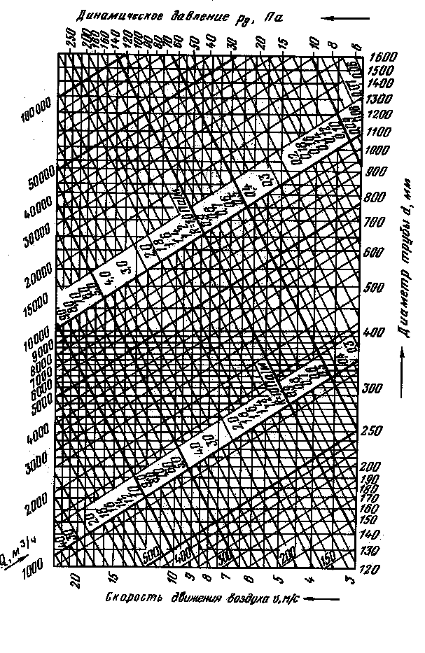
Fig. 3.2 Nomogram for calculations of round steel air ducts
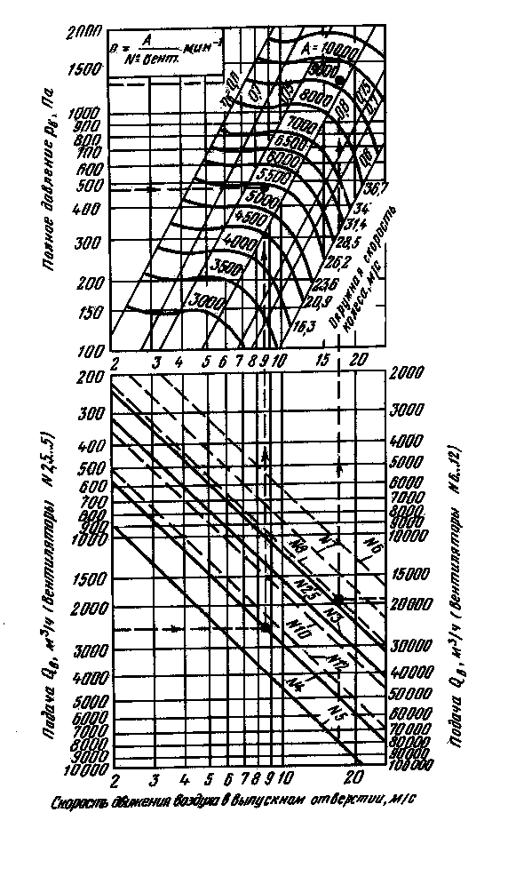
Fig.3.3 Nomogram for selecting centrifugal fans of the Ts4-70 series
Local resistance coefficient
First, let's define the local resistance coefficient. Local resistances are called point pressure losses associated with changes in the flow structure. There are many components in ventilation that play the role of local resistance:
- air duct rotation,
- narrowing or widening of the flow,
- air entry into the air intake shaft;
- “tee” and “cross”;
- supply and exhaust grilles and air distributors;
- air distributors;
- diffuser;
- dampers, etc.
Their KMS are calculated using certain formulas, and then they participate in determining local pressure losses. In mathematical terms, the local loss coefficient is the ratio of the loss of a known pressure in local resistance to the velocity pressure.

The coefficient of local resistance depends on the shape and type of local resistance, the roughness of the air duct and, oddly enough, on the Reynolds number. For dampers and other shut-off valves, the opening degree is added to the above.
The relationship between the CMR and the Reynolds number is expressed in the formula

Values of coefficients B
for some local resistances
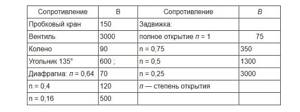
The larger the Re number, the less the coefficient depends on it. Complete independence of the local resistance coefficient from the number Re in the ventilation system occurs for sharp transitions at Re > 3000, and for smooth transitions - at Re > 10000.
The total coefficient of local resistance in a section of the air duct is equal to the sum of all local coefficients in this section.
In practice, there is no special time for calculating the CMC, so designers use tables from reference books and other sources. Moreover, why waste a lot of time searching for formulas and calculations if it has already been done for you. Many manufacturers of silencers, valves and grilles are happy to indicate the value of the local resistance coefficient in their catalogs. But, of course, if you haven’t found any data at all, then you need to resort to mathematics.
Local hydraulic resistance includes various devices and elements installed on pipelines in which the normal flow movement is disrupted as a result of its deformation with a change in the direction and value of the average speed and the occurrence of vortex formation. As a result of the deformation of a turbulent flow, intense mixing of particles and an exchange of momentum between liquid particles occurs.Elements and devices include shaped and pipeline fittings: bends (elbows), adapters, tees, crosses, diaphragms, screens, shut-off control valves (taps), gate valves, shutters, safety and control valves, suction tips installed at the inlet of the pump pipe , etc.
The simplest local hydraulic resistances can be divided according to the direction of the average velocity vector.
1. The speed is variable with a constant direction of fluid flow.
For example, the expansion of a pipe (channel) can be gradual or sudden; narrowing of the pipe (channel) - smooth or sudden.
2. The speed is constant when the direction of flow changes.
For example, the turn of a pipe (channel) in the form of a smooth or sharp one (see figure).
More complex local resistances include resistances in which the velocity vector changes in value and direction, as well as when flows merge or separate. For example, gate valves, valves, valves, etc., as well as tees, crosses (see figure).
In such resistances, as a result of sudden changes in direction and speed, a very significant deformation of the flow occurs with the occurrence of intense vortex formation.
Local pressure losses are the costs of specific mechanical energy caused by the work of friction forces and vortex formation to overcome local resistance by the fluid flow. Flow energy is expended to maintain vortices in a certain zone.
Weisbach proposed to determine local pressure losses using the formula:
For a quadratic resistance region ζ = ζsq. Typically, in hydraulic calculations, ζkv is taken.
The quadratic region is when the flow has a turbulent regime; in this regime, the resistance to fluid movement is proportional to the square of the speed.
The coefficient ζ is found empirically, and the values of ζkv for various local resistances, B, are given in hydraulic reference books.
In practice, plumbers and installation engineers are unlikely to encounter a task that requires immediate knowledge of these parameters like: [ B, ζ, ζkv
]. You will need them if you are defending a PhD thesis or inventing, for example, a special crane at high speeds. So you won't need it. In practice, these numbers are usually very small and are not taken into account. But there are exceptions.
Below we will analyze the main problems encountered in local resistance that should be taken into account.
In general, there are a lot of formulas, I won’t give you so many so as not to burden your head. In addition, most formulas are not even useful in practice.
Let's consider two options for local resistances, these are options for rounding the pipe:
1
. Rounded corner(s)
2
. Right angle - knee (b)
See picture.
Let's look at the second option first, since it causes greater hydraulic resistance than with a rounded corner.
To find the coefficient of local resistance due to knee rotation (see Fig. [b]), we use the formula:
This formula is applicable to small diameter pipes up to a maximum of 50mm. The larger the diameter, the lower the local resistance coefficient.
| ζ-coefficient of local resistance. β-angle of abduction (elbow). |
Also, for a clear understanding, I will give a table:
This table corresponds to experiments with pipes with a diameter of 30 mm.
It can be seen that at 90° the local resistance coefficient is approximately equal to unity.
We insert the resulting local resistance coefficient into the formula:
And we get the pressure loss in meters.
In practice, this is usually a very small number and is not significantly noticeable. But if you have very high fluid speeds and the number of such local resistances is in the tens, then you should definitely count them. Each loss in local resistance is simply added to the rest of the number if they are connected in series (one after another).
An equally important formula for finding local resistance on bends with a twisted corner (see Fig. [a]). These can also be bent pipes at a certain radius and a certain angle.
This formula is valid provided:
| d is the internal diameter of the pipe, converted to meters. R is the corner radius, converted to meters. β-pipe bending angle. |
This formula will be needed by those who install warm water floors, in which it is very important to understand that each bend of the pipe is an additional local resistance. Therefore, the fewer turns there are, the less pressure loss there will be, the easier and faster the fluid will flow. Therefore, it is very advisable to use the snail method when laying out heated floors. Since the snail method allows you to lay out the pipe on the floor surface so that there are fewer turns in it, thereby reducing pressure loss.
For those who want to make a warm water floor with their own hands, here is more information: Do-it-yourself water heated floor.
Table: (Value of the resistance coefficient ζ for a 90° bend at various roundings).
I think you already remember that we insert the resulting coefficient into the formula:
and we get the loss of pressure at the local resistance. If there are a lot of them, and there are a lot of them especially in heated floors. You just need to find the pressure loss at one local resistance and multiply the resulting answer by the number of turns.
Well, that’s actually all that is useful to us for calculating local resistance. If something is not clear, write a comment, I will definitely answer.
Next: Professional calculation of pipe diameter for water supply
| Like |
| Share |
| Comments (+) [ Read / Add ] |
All about the country house Water supply Training course. Automatic water supply with your own hands. For Dummies. Malfunctions of the well automatic water supply system. Water wells Well repair? Find out if you need it! Where to drill a well - outside or inside? In what cases does cleaning a well make no sense Why pumps get stuck in wells and how to prevent it Laying a pipeline from a well to a house 100% Protecting the pump from dry running Heating Training course. Do-it-yourself water heated floor. For Dummies. Warm water floor under laminate Educational Video course: According to HYDRAULIC AND THERMAL CALCULATIONS Water heating Types of heating Heating systems Heating equipment, heating batteries Heated floor system Personal article on heated floors Operating principle and operating diagram of a heated water floor Design and installation of a heated floor Do-it-yourself water heated floor Basics materials for heated water floors Installation technology of water heated floors System of heated floors Laying step and methods of laying heated floors Types of water heated floors All about coolants Antifreeze or water? Types of coolants (antifreeze for heating) Antifreeze for heating How to properly dilute antifreeze for the heating system? Detection and consequences of coolant leaks How to choose the right heating boiler Heat pump Features of a heat pump Heat pump operating principle About heating radiators Methods of connecting radiators. Properties and parameters. How to calculate the number of radiator sections? Calculation of thermal power and number of radiators Types of radiators and their features Autonomous water supply Scheme of autonomous water supply Construction of a well Cleaning a well with your own hands Experience of a plumber Connecting a washing machine Useful materials Water pressure reducer Hydraulic accumulator. Operating principle, purpose and configuration. Automatic air release valve Balancing valve Bypass valve Three-way valve Three-way valve with ESBE servo drive Thermostat for radiator Manifold servo drive. Selection and connection rules. Types of water filters. How to choose a water filter for water. Reverse osmosis Sludge filter Non-return valve Safety valve Mixing unit. Principle of operation. Purpose and calculations. Calculation of the CombiMix Gidrostrelka mixing unit. Operating principle, purpose and calculations. Indirect heating storage boiler. Principle of operation. Calculation of a plate heat exchanger Recommendations for the selection of PHE when designing heat supply facilities About contamination of heat exchangers Indirect water heating water heater Magnetic filter - protection against scale Infrared heaters Radiators. Properties and types of heating devices. Types of pipes and their properties Indispensable tools for a plumber Interesting stories A scary tale about a black installer Water purification technologies How to choose a filter for water purification Let's think about sewerage Sewage treatment plants in a rural house Tips for a plumber How to evaluate the quality of your heating and plumbing system? Professional recommendations How to choose a pump for a well How to properly equip a well Water supply for the garden How to choose a water heater An example of installing equipment for a well Recommendations for the configuration and installation of submersible pumps What type of water supply accumulator should you choose? Water cycle in an apartment - vent pipe Removing air from a heating system Hydraulics and heating engineering Introduction What is hydraulic calculation? Discrepancy in hydraulic calculation Physical properties of liquids Hydrostatic pressure Let's talk about resistance to the passage of liquid in pipes Modes of fluid movement (laminar and turbulent) Hydraulic calculation for pressure loss or how to calculate pressure loss in a pipe Local hydraulic resistance Professional calculation of pipe diameter using formulas for water supply How to choose a pump according technical parameters Professional calculation of water heating systems. Calculation of heat loss of the water circuit. Hydraulic losses in a corrugated pipe Heat engineering. Author's speech. Introduction Heat transfer processes Thermal conductivity of materials and heat loss through the wall How do we lose heat with ordinary air? Laws of thermal radiation. Radiant warmth. Laws of thermal radiation. Page 2. Heat loss through a window Factors of heat loss at home Start your own business in the field of water supply and heating systems Question on hydraulic calculations Designer of water heating Pipe diameter, flow speed and coolant flow. We calculate the diameter of the heating pipe. Calculation of heat losses through the radiator. Power of the heating radiator. Calculation of the power of radiators. Standards EN 442 and DIN 4704 Calculation of heat loss through building envelopes Find heat loss through the attic and find out the temperature in the attic Selecting a circulation pump for heating Transfer of thermal energy through pipes Calculation of hydraulic resistance in a heating system Distribution of flow and heat through pipes. Absolute schemes. Calculation of a complex associated heating system Heating calculation. Popular myth Calculation of heating of one branch along the length and KMS Calculation of heating. Selection of pump and diameters Heating calculation. Two-pipe dead-end Heating calculation. Single-pipe sequential heating calculation. Two-pipe associated Calculation of natural circulation. Gravity pressure Calculation of water hammer How much heat is generated by pipes? We are assembling a boiler room from A to Z... Heating system calculation Online calculator Calculation program Heat loss of the room Hydraulic calculation of pipelines History and capabilities of the program - introduction How to make a calculation of one branch in the program Calculation of the KMS angle of the outlet Calculation of the KMS of heating and water supply systems Pipeline branching - calculation How to calculate in the program single-pipe heating system How to calculate a two-pipe heating system in a program How to calculate radiator flow in a heating system in a program Recalculation of radiator power How to calculate a two-pipe associated heating system in a program. Tichelman loop Calculation of a hydraulic separator (hydraulic arrow) in the program Calculation of a combined circuit of heating and water supply systems Calculation of heat loss through enclosing structures Hydraulic losses in a corrugated pipe Hydraulic calculation in three-dimensional space Interface and control in the program Three laws/factors for selecting diameters and pumps Calculation of water supply with self-priming pump Calculation of diameters from the central water supply Calculation of water supply for a private house Calculation of a hydraulic arrow and collector Calculation of a hydraulic arrow with many connections Calculation of two boilers in a heating system Calculation of a single-pipe heating system Calculation of a two-pipe heating system Calculation of a Tichelman loop Calculation of a two-pipe radial distribution Calculation of a two-pipe vertical heating system Calculation of a single-pipe vertical heating system Calculation of a warm water floor and mixing units Recirculation of hot water supply Balancing adjustment of radiators Calculation of heating with natural circulation Radial distribution of a heating system Tichelman loop - two-pipe associated Hydraulic calculation of two boilers with a hydraulic arrow Heating system (not Standard) - Another piping scheme Hydraulic calculation of multi-pipe hydraulic arrows Radiator mixed system heating - passing from dead ends Thermoregulation of heating systems Pipeline branching - calculation Hydraulic calculation for pipeline branching Calculation of a pump for water supply Calculation of warm water floor contours Hydraulic calculation of heating. Single-pipe system Hydraulic heating calculation. Two-pipe dead-end Budget option for a single-pipe heating system for a private house Calculation of the throttle washer What is KMS? Calculation of a gravity heating system Designer of technical problems Extension of a pipe Requirements SNiP GOSTs Requirements for a boiler room Question for a plumber Useful links for a plumber - Plumber - ANSWERS!!! Housing and communal problems Installation work: Projects, diagrams, drawings, photos, descriptions. If you're tired of reading, you can watch a useful video collection on water supply and heating systems
Table of local resistance coefficients
We have analyzed technical literature and other sources and provide you with tables with CMR values for different elements of the system for your use. In our case, these are catalogs from VEZA, Belimo, a reference book by the designer N, N, Pavlov and a reference book by R.V. Shchekin.
With this material, the editors of the magazine “Climate World” continue the publication of chapters from the book “Ventilation and air conditioning systems. Design recommendations for industrial and public buildings.” Author Krasnov Yu.S.
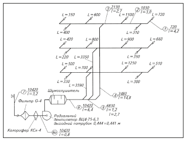
The aerodynamic calculation of air ducts begins with drawing an axonometric diagram (M 1: 100), putting down the numbers of sections, their loads L (m 3 / h) and lengths I (m). The direction of the aerodynamic calculation is determined - from the most distant and loaded area to the fan. When in doubt when determining a direction, consider all possible options.
The calculation begins from a remote section: the diameter D (m) of a round or the cross-sectional area F (m 2 ) of a rectangular air duct is determined:
The recommended speed is as follows:
| at the beginning of the system | near the fan | |
| Administrative buildings | 45 m/s | 812 m/s |
| Industrial buildings | 56 m/s | 10/16 m/s |
The speed increases as you approach the fan.
According to Appendix H from [30], the nearest standard values are taken: DCT or (a x b)st (m).
|
| Rice. 1. Axonometric diagram of the air duct |
Actual speed (m/s):
| or |
Hydraulic radius of rectangular ducts (m):
| Reynolds criterion: |
(for rectangular air ducts Dst=DL).
Hydraulic friction coefficient:
λ=0.3164 × Re-0.25 at Re≤60000,
λ=0.1266 × Re-0.167 at Re 3 /h
| length L, m | υrec, m/s | section a × b, m | υf, m/s | Dl,m | Re | λ | Kmc | losses in the area Δр, pa | ||
| PP grid at the outlet | 0,2 × 0,4 | 3,1 | — | — | — | 1,8 | 10,4 | |||
| 1 | 720 | 4,2 | 4 | 0,2 × 0,25 | 4,0 | 0,222 | 56900 | 0,0205 | 0,48 | 8,4 |
| 2 | 1030 | 3,0 | 5 | 0,25× 0,25 | 4,6 | 0,25 | 73700 | 0,0195 | 0,4 | 8,1 |
| 3 | 2130 | 2,7 | 6 | 0,4 × 0,25 | 5,92 | 0,308 | 116900 | 0,0180 | 0,48 | 13,4 |
| 4 | 3480 | 14,8 | 7 | 0,4 × 0,4 | 6,04 | 0,40 | 154900 | 0,0172 | 1,44 | 45,5 |
| 5 | 6830 | 1,2 | 8 | 0,5 × 0,5 | 7,6 | 0,50 | 234000 | 0,0159 | 0,2 | 8,3 |
| 6 | 10420 | 6,4 | 10 | 0,6 × 0,5 | 9,65 | 0,545 | 337000 | 0,0151 | 0,64 | 45,7 |
| 6a | 10420 | 0,8 | Yu. | Ø0.64 | 8,99 | 0,64 | 369000 | 0,0149 | 0,9 | |
| 7 | 10420 | 3,2 | 5 | 0,53 × 1,06 | 5,15 | 0,707 | 234000 | 0.0312×n | 2,5 | 44,2 |
| Total losses: 185 | ||||||||||
| Table 1. Aerodynamic calculation |
| Note. For brick channels with an absolute roughness of 4 mm and υf = 6.15 m/s, correction factor n = 1.94 (32, Table 22.12.) |
The air ducts are made of galvanized sheet steel, the thickness and size of which correspond to approx. N from [30]. The material of the air intake shaft is brick. Adjustable grilles of the PP type with possible sections: 100 x 200; 200 x 200; 400 x 200 and 600 x 200 mm, shading coefficient 0.8 and maximum air outlet speed up to 3 m/s.
Local head losses
This page contains information on local resistance coefficients, which can be used to calculate local pressure losses in engineering practice problems
Gate valve
When calculating pipeline systems, the resistance coefficient of an open valve is assumed to be ζzadv = 0.1 - 0.2 . If the valve is closed by a certain amount, then the resistance coefficient directly depends on the degree of closure. Below is a table of the dependence of the valve resistance coefficient on the degree of closure. The greater the degree of closure, the greater the resistance coefficient.
| Closure degree (dh)/d | 1/8 | 2/8 | 3/8 | 1/2 | 5/8 | 3/4 | 7/8 |
| ζrear | 0,07 | 0,26 | 0,81 | 2,06 | 5,52 | 17,0 | 97,8 |
Ball valve
The resistance coefficient of a ball valve depends on its diameter (nominal diameter). Below is a table with coefficients. The diameter of the tap is given in inches (since it is most often connected to pipes with a thread), but below is the corresponding diameter in mm
| D, inches | 1/2 | 3/4 | 1 | 1 1/4 | 1 1/2 | 2 |
| D, mm | 15 | 20 | 25 | 32 | 40 | 50 |
| ζ | 0,26 | 0,13 | 0,12 | 0,11 | 0,103 | 0,101 |
According to the rules of the Russian language, in relation, in this case, to shut-off valves, the element of which is a ball, the correct pronunciation and spelling will be ball valve , and not ball valve. Ball means color (smoky gray)
Wikipedia
Valve
The local valve resistance coefficient for calculations can be taken equal to 6
ζvent = 6
Butterfly valve
The resistance coefficient of the butterfly valve for technical calculations can be taken equal to 0,15 — 0,25
.
Check valve
The resistance coefficient of the check valve for technical calculations can be taken equal to 1,7
.
Smooth turn
The drag coefficient for a smooth flow rotation depends on the rotation angle (α). For standard 90° bends, coefficient ζ = 0.5 - 0.6 . The resistance coefficient when turning at an arbitrary angle (α) can be found by the formula: ζpov = ζ 90 α/90
Flip flop
The local drag coefficient during a sharp turn depends on the steering angle (α). This relationship is presented in tabular form below
| α | 0 | 20 | 30 | 45 | 60 | 75 | 90 | 110 | 130 | 150 | 180 |
| ζpov | 0 | 0,13 | 0,16 | 0,32 | 0,56 | 0,81 | 1,19 | 1,87 | 2,59 | 3,20 | 3,60 |
Sudden expansion
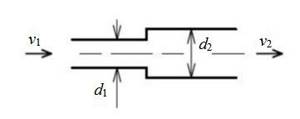
The head loss can be calculated from the speed before (v₁) or after the diameter change (v₂)
Sudden contraction
The head loss due to a sudden contraction can also be calculated from the velocity (v₂) after the contraction using the formula below:
Smooth expansion (expanding transition)
The local resistance coefficient for a standard expanding junction can be taken as ζtrans.ext. = 0.25
! When calculating the head loss, the speed is taken over the smaller diameter!
.
Smooth narrowing (tapering transition)
The local resistance coefficient for a standard tapering transition can be taken as ζtrans.constriction. = 0.1
When calculating pressure loss, the speed is also taken over the smaller diameter
Check valve with mesh
When calculating the pressure loss on a check valve with a mesh, which is installed in certain cases on the suction pipeline from a pump for drawing water from water bodies, the local resistance coefficient can be taken: ζrev.cl = 5.0 - 10.0
.
Pipe entrance
a) ζin = 0.5
b) ζin = 0.2
c) ζin = 0.15
d) ζin = 0.5 - 1.0
The coefficient of local resistance at the entrance to the pipe from the reservoir depends on how the entry point is “designed”. Rounded edges (option B) reduce hydraulic resistance. If the pipe is placed inside (option D), then the resistance coefficient, on the contrary, is greater.
Pipe entrance with a turn
The resistance coefficient at the entrance to the pipe from the tank ζin.α also depends on the angle of rotation α. The larger the angle, the greater the local resistance.
| α | 90 | 75 | 60 | 45 |
| ζin.α | 0,50 | 0,59 | 0,70 | 0,81 |
Exit to the tank below the liquid level
The pressure loss at the exit from the pipeline into the tank under the liquid level is equal to the velocity pressure of the flow at the exit point, i.e. resistance coefficient ζ out = 1
.
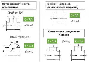
Losses associated with fluid flow through tees
