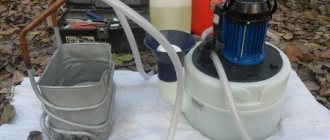
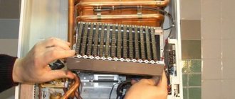
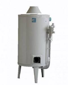
Automatic gas water heater AGV-80
Automatic gas water heaters of the AGV-80 type were manufactured by the Rostov Gas Equipment Plant and were intended for local water heating of premises or hot water supply. Currently, the devices are not in production, but many of them have been in operation for more than 40 years and continue to work. Initially, the device was intended to be used only for hot water supply; it had a 0.6 MPa safety valve in its design. Subsequently, AGV-80 began to be used for open heating systems, which became its main application.
AGV-80 has the following technical characteristics:
- heat load – 6,000 kcal/hour;
- heated room area – up to 60 m²;
- water temperature setting – from 40 to 90 °C;
- Tank capacity – 80 liters.
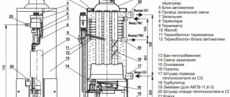
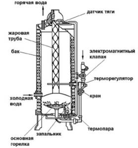
The basis of the water heater is a welded metal tank 3-4 mm thick, which is a heat exchanger. The inside of the tank is zinc coated, which provides the AGV-80 with a long service life. The top of the tank is covered with a casing made of sheet steel. Thermal insulation made of fiberglass ensures that the surface temperature of the casing does not exceed 40 °C. The main burner of the water heater is installed in the firebox, bounded at the top by the bottom of the tank. The igniter supplies flame to the main burner and thermocouple. The thermostat ensures that the water temperature in the tank is maintained within the range from 40 to 90 °C. Closing of the solenoid valve when the igniter flame goes out should occur within 60 seconds, and when the draft sensor is activated - within 20-60 seconds.
Automatic gas water heater AGV-80
Inside the tank, along its entire height, there is a flame tube into which a heat flow extender (turbulator) is inserted, which helps to increase the efficiency of the water heater. The main burner AGV-80 was initially made of cast iron, later steel was used.
The solenoid valve is the basis of the automatic safety system, which ensures that the gas supply is stopped when the igniter goes out. There is also an automatic system that ensures that the gas supply is stopped if the draft in the chimney is disrupted. When it is triggered, the gas supply to the igniter first stops, and then the solenoid valve closes. This principle of automatic operation is called “with gas removal from the igniter.” The solenoid valve works together with the thermocouple.
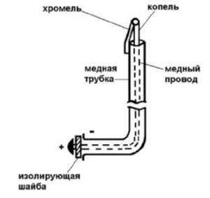
A thermocouple consists of two metals connected together: chromel and copel, which form a hot junction. Chromel is connected to a copper tube, and copel is connected to a copper wire, which is insulated from the tube along the entire length of the thermocouple with insulation based on asbestos thread. When the end of a thermocouple is heated, it produces thermoelectromotive force (electrical voltage). The end of the copper tube is flared and is fitted with a union nut, which, when tightened, ensures contact between the thermocouple and the valve solenoid. The thermocouple contact is made of solder. To ensure that the contact is isolated from the copper tube, an insulating washer is installed.
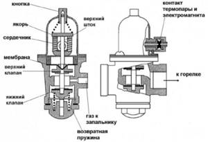
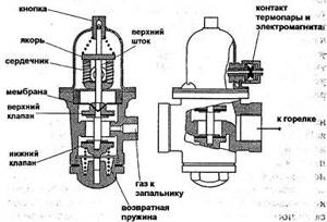
The solenoid valve consists of two parts: gas and electric, between which is sandwiched a membrane that prevents gas leakage. The electrical part contains an electromagnet to which a thermocouple is connected. In the gas part there are two valves located on the same stem. They will shuffle down when you press the button. At the same time, they are pressed upward by the return spring.
Electromagnetic valve AGV-80
The valves can be in three positions: uppermost – the gas supply to the main burner and igniter is shut off; extreme lower - the gas supply to the main burner is shut off, and the igniter is open; and intermediate - gas flows to both the main burner and the igniter.
In the uppermost position, the lower valve is pressed against the seat by the return spring. In the figure, this position of the valves is shown on the right. The gas that entered from the left inside the gas part cannot go further either to the main burner or to the igniter.
When the button is pressed down, it uses the stem to move the valve to its lowest position. In this case, the lower valve moves away from the seat and allows gas to flow upward. At the same time, the upper valve is pressed against its seat, so gas does not flow further. It can only go to the igniter. At the same time, in the electrical part, the armature is pressed against the core of the electromagnet.
After igniting the igniter, its flame heats the thermocouple junction, which after 1 minute produces a current to the electromagnet, which begins to hold the armature. If the button is smoothly released, the valve system, under the action of the return spring, will begin to move upward until the upper rod rests its shoulders against the drawn anchor. In this case, the valves will be installed in the middle (working) position, in which gas flows to both the igniter and the main burner. In Figure 95 this position of the valves is shown on the left.
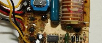
Speaker repair
AGV – 80 gas heating boiler. Technical characteristics of agv-80:
- Heat load 6000kcal/h
- Water temperature setting 40 - 90gr/C
- Heated room area up to 60m2
Main components of the AGV-80 heating boiler.
- Galvanized tank (80 liters), thermal insulation, min. cotton wool. In the center of the tank is a flame tube with a heat flow extender.
- The main burner, in front of it, the tap regulates the gas supply.
- Automatic security.
- For flame, solenoid valve, thermocouple, igniter.
- For draft, tee, connected pipe, draft sensor.
- Temperature-thermostat.
Boiler solenoid valve. The boiler solenoid valve consists of two parts: gas and electromagnetic. There is a membrane between them. The thermocouple consists of two metals, chromel and copel, welded together. The flame heats the boiler thermostat, generating an electric current that magnetizes the core. By pressing the start button, the armature is pressed against the core by a pusher, while the paired valves move inside the gas part, opening the gas to the boiler igniter and compressing the return spring. At the end of the thermocouple warming up for 60 seconds, you must smoothly release the boiler button; under the action of the return spring, the paired valves are shifted back - 2.3 mm. Gas opens to both the igniter and the main burner of the boiler. The valve cannot return completely to its original position. They are held by an anchor magnetized to the core. If the igniter goes out, then the thermocouple of the heating boiler cools down and the magnet releases the armature; the return spring pushes the valve to its original position, no gas flows to the burner.
Malfunctions of the gas heating boiler AGV-80
- Contamination of the surface of the core and armature (clean, degrease)
- Thermocouple burnt out (Replace)
- No electrical contact.
Automatic traction (with gas removal from the igniter)
Gas from the electromagnetic valve of the heating boiler flows through the tee to the igniter, as well as through the connecting tube to the draft sensor installed under the hood of the device. The draft sensor is a bimetallic plate with a plug, which, during normal draft, closes the gas from the connecting tube. When the draft is covered, combustion products come out from under the hood and heat the bimetallic plate. It unbends, the plug opens the gas from the connecting tube, and gas is supplied to the igniter. Response time from 10 to 60 seconds.
Gas boiler thermostat. Operation accuracy 5gC, thermostat parts.
- Frame.
- Toggle lever system.
- Valve with spring.
- A brass tube with an invectar rod is screwed into it.
- Lever for thermostat.
When the water in the tank is heated, the brass tube lengthens, but the intar rod does not. The rod moves behind the tube and stops pressing on the system of closed levers, which, under the action of a spring, closes the valve with a click, blocks the passage of gas to the burner; when the water cools, the brass tube shortens; the rod presses on the levers, they close and turn off the valve. When the setting lever is rotated counterclockwise, the response temperature increases.
Malfunction of the boiler thermostat.
- The thermostat does not work and cannot be adjusted: The lever system has stretched or burst.
- The large or small levers are deformed.
- The supporting edges of the levers are worn
- The valve spring has weakened.
There is dirt under the valve.
AGV, or automatic gas water heater, is an element of the heating system, thanks to which it becomes easy to operate along with a fairly long service life. However, the presence of these characteristics is possible only if the gas boiler is properly installed and properly maintained.
Epilogue
In conclusion, it is worth recalling that the repair of AGV, along with the maintenance of gas boilers, are quite difficult operations that must be carried out by specialists. Only by observing this condition can the risk of damage to housing and injury to its inhabitants be eliminated.
Repair of AGV, OAGV, gas heating boilers 8-903605-49-99
The main burner AGV-80 was made of cast iron, later it was made of steel.
⇐ PreviousPage 7 of 10Next ⇒
The solenoid valve is the basis of the automatic safety system, which ensures that the gas supply is stopped when the igniter goes out. There is also an automatic system that ensures that the gas supply is stopped if the draft in the chimney is disrupted. When it is triggered, the gas supply to the igniter first stops, and then the solenoid valve closes. This principle of automatic operation is called “with gas removal from the igniter.” The solenoid valve works together with the thermocouple.
Rice. 30. Thermocouple AGV-80
The thermocouple consists of two metals connected to each other: chromel and copel (Fig. 30). Chromel is connected to a copper tube, and copel is connected to a copper wire, which is insulated from the tube along the entire length of the thermocouple with insulation based on asbestos thread. When the end of a thermocouple is heated, it produces a thermo-emf . (electrical voltage). The end of the copper tube is flared and a union nut is placed on it, which, when tightened, ensures contact between the thermocouple and the valve solenoid.
The thermocouple contact is made of solder. To ensure that the contact is isolated from the copper tube, an insulating washer is installed.
Rice. 31. Electromagnetic valve AGV-80
The solenoid valve (Fig. 31) consists of two parts: gas and electric, between which a membrane is sandwiched that prevents gas leakage. The electrical part contains an electromagnet to which a thermocouple is connected. In the gas part there are two valves located on the same stem. They move down when you press the button. At the same time, they are pressed upward by the return spring.
The valves can occupy three positions : uppermost—the gas supply to the main burner and igniter is shut off; extreme bottom - the gas supply to the main burner is shut off, and the igniter is open; and intermediate - gas flows to both the main burner and the igniter.
In the uppermost position, the lower valve is pressed against the seat by the return spring. In Fig. 31 this position of the valves is shown on the right. The gas that entered from the left inside the gas part cannot go further either to the main burner or to the igniter.
When the button is pressed down, it uses the stem to move the valve to its lowest position. In this case, the lower valve moves away from the seat and allows gas to flow upward. At the same time, the upper valve is pressed against its seat, so gas does not flow further. It can only go to the igniter. At the same time, in the electrical part, the armature is pressed against the core of the electromagnet.
After the igniter is ignited, its flame heats the thermocouple junction, which after 1 minute produces a current to the electromagnet, which begins to hold the armature. If the button is smoothly released, the valve system, under the action of the return spring, will begin to move upward until the upper rod rests its shoulders against the drawn anchor. In this case, the valves will be installed in the middle (working) position, in which gas flows to both the igniter and the main burner. In Fig. 31 this position of the valves is shown on the left.
When the igniter goes out , the thermocouple will cool down, stop giving current to the electromagnet, it will stop attracting the armature, and the entire valve system, under the action of the return spring, will move to the uppermost position, at which the lower valve will be closed. Gas will not go to the igniter and the main burner.
The most common malfunction of safety automatics based on a solenoid valve is the inability to be in the open position when there is a pilot flame - “ the valve does not hold.”
The reasons may be:
1. Violation of the electrical circuit between the thermocouple and the electromagnet - open or short circuit. Maybe:
-lack of contact between the thermocouple and electromagnet terminals;
- violation of the insulation of the copper wire of the thermocouple and short circuit with the tube;
-excessive tension of the union nut and rupture of the solder at the point of contact of the sleeve with the base;
- violation of the insulation of the turns of the electromagnet coil, shorting them to each other or to the core;
- separation of the copel core from the chromel thermocouple tube;
- disruption of the magnetic circuit between the armature and the core of the electromagnet coil due to oxidation, dirt, grease film, etc. In this case, it is necessary to clean the surfaces using a piece of coarse cloth.
2. Insufficient heating of the thermocouple:
- the working end of the thermocouple is smoked;
- the hole in the igniter head or its nozzle is clogged;
- the igniter head is installed incorrectly.
3.During operation, the thermocouple may burn out and must be replaced.
The design, principle of operation and possible malfunctions of solenoid valves used on other household gas-using equipment are in many ways similar to the design, principle of operation and malfunctions of the AGV-80 solenoid valve.
The traction automation consists of a traction sensor installed under the AGV-80 hood and a tube connecting the sensor to a tee on the solenoid valve.
Rice. 32. Traction sensor AGV-80
The draft sensor (Fig. 32) consists of a bimetallic plate, at the end of which there is a valve with a seal and a bracket that is attached to the body of the water heater. A bimetallic plate is attached to the bracket from above using two screws and nuts.
The bracket has a hole into which a fitting fits from below, clamped with a nut from above to fix the position.
The fitting has a tapered end, which turns the 2.5 mm diameter through-drilling inside the fitting into a valve seat. A tube with a tension nut is connected to the fitting, which is connected to a tube going to the solenoid valve.
A tee is installed on the solenoid valve fitting that supplies gas to the igniter, to which tubes are attached with union nuts that supply gas to both the igniter and the draft sensor installed under the AGV-80 hood.
In the absence of draft, the combustion products, coming out from under the hood, heat the bimetallic plate, which unbends, and the valve with a seal moves away from the conical end of the fitting. Gas from the tube connecting the draft sensor to the solenoid valve begins to be discharged. Due to the fact that the diameter of the hole in the fitting exceeds the diameter of the hole in the throttle installed in the tee, the gas supply to the igniter will sharply decrease. It will stop heating the thermocouple, which will stop producing current, and the solenoid valve will close. The gas supply to the main burner and igniter will stop.
Failure - wear of the seal, which does not provide a hermetically sealed seal of the sensor fitting. In this case, the gas will be released and the pilot flame will decrease. Automatic traction control “with gas removal from the igniter”, installed on other household gas-using equipment, works in a similar way.
The thermostat (Fig. 33) is located along the gas flow below the solenoid valve. It stops the gas supply to the main burner when the set water temperature is reached and resumes the gas supply after it has cooled.
Rice. 33. Temperature regulator AGV-80
The thermostat consists of a body, a brass tube with an Invar rod running inside, a lever system, a valve with a spring, and a setting regulator. One end of the brass tube is screwed into the thermostat housing, and the Invar rod is screwed into the free end of the brass tube placed in the tank. The second end of the rod rests against a lever located in the thermostat housing. The brass tube is located in the tank and heats up and cools down along with the water.
The lever system consists of two hinged levers and a spring. An Invar rod rests on one end of the system, and the other end of the lever system acts on the valve. The lever system can be in two positions - open and closed. The valve is constantly pressed against the seat in the thermostat housing by a spring, which tends to block the passage of gas to the main burner. The tuning regulator consists of a tightening lever with a clamp, which is placed on an Invar rod. Using a lever and a clamp, the rod can be rotated in the thread of the brass tube, shortening or lengthening its free end. When you rotate the adjustment lever counterclockwise, the temperature at which the thermostat operates increases.
When the water in the tank is heated, the brass tube lengthens, and the Invar rod practically does not change its length (very low linear expansion coefficient). The rod stops pressing on the lever system, which moves to the closed position and stops pressing on the valve. The valve, under the action of a spring, closes the gas passage to the burner.
Once the water has cooled , the brass tube is shortened and the Invar rod presses against the end of the lever system, which moves to the open position. The valve, under the action of the second end of the lever system, opens the passage of gas to the burner, which lights up from the igniter.
Malfunctions of the AGV-80 thermostat:
1. The thermostat does not adjust and does not work:
— the large or small lever is deformed;
— the levers have moved out of place;
— the supporting edges of the levers are worn out;
— the spring of the lever system is skewed.
2. The thermostat operates, but does not stop the gas supply:
— the valve spring is weak;
— dirt got under the valve;
— the valve stem jams in the guide sleeve.
It should be noted that the valves of many thermostats are specially made in such a way that when closing the valve allows part of the gas to flow to the burner, which must operate in the “Low flame” mode.
AOGV-23
The gas heating device with a water circuit AOGV-23 is designed for heating premises with an area of 140-200 m2 (depending on climatic conditions). AOGV-23 has the following technical characteristics:
— thermal power — 23.2 kW;
— nominal gas pressure — 130 mm w.c.;
— tank capacity — 64 l;
- water temperature setting - 50-90°C.
Rice. 34. AOGV-23
The device (Fig. 34) is made in the form of a cylindrical floor cabinet, the front side of which is closed with a door. The basis of the AOGV-23 is a vertical reservoir (tank) made of steel, into which three sections are welded to improve heat transfer. At the bottom of the tank there is a firebox, there is a window for ignition and observation of combustion. The combustion products pass through the center of the tank and give off heat to the water, then they enter the smoke exhaust pipe. There is also a pipe passing through the tank through which gas is supplied to the automation unit.
The AOGV-23 burner is an injection burner , it has a round shape and is made of cast iron. The burner nozzle has a disk that moves along the thread. It serves to regulate the supply of primary air.
The AOGV-23 automation (Fig. 35) is assembled into a single unit; it controls the igniter flame, chimney draft and water temperature.
The solenoid valve serves to completely stop the gas supply to the main burner and igniter when the igniter goes out. When the pilot light is lit and its flame heats the end of the thermocouple, the thermocouple current flows through the electromagnet winding. The attractive force of the electromagnet is sufficient to hold the armature in the down position. In this case, the upper valve of the automation unit is open, gas flows to the igniter and to the main burner. If the pilot light goes out, the thermocouple current will disappear and the electromagnet will release the armature. Under the action of the spring, the upper valve will block the gas access to the igniter and the main burner.
If the armature is not held by the electromagnet while the igniter is burning, then the device cannot be used. In this case, it is prohibited to hold the button pressed in any way, as this will turn off the automation unit.
The thermostat is designed to automatically regulate water temperature. The automation unit contains a bellows, which is connected to a thermal cylinder by a capillary tube. The thermal cylinder is placed in the tank. “thermocylinder - bellows” system is filled with kerosene.
As the temperature of the water in the tank increases, the kerosene begins to expand and the bellows corrugations diverge.
Rice. 35. Automation unit AOGV-23
The rod lifts up and, using a lever, brings the lower valve closer to the seat, reducing the passage of gas to the main burner. With a further increase in temperature, the valve rises up to the end, switching the burner to the “low flame” mode. As the water cools, the kerosene decreases in volume and the bellows contracts. The rod and lever move down, opening the bottom valve. The gas supply to the main burner increases .
A certain position of the upper edge of the nut corresponds to a certain temperature on the setting scale. The higher the nut is screwed, the higher the bellows is raised, and with it the valve. Accordingly, less gas passes through and the setting temperature is lower.
It is forbidden to unscrew the nut below the line indicating 90°C. This leads to the automation being turned off and the water heating above the permissible temperature. It is prohibited to tighten the nut to change from the current temperature to a lower one when the water in the tank has not cooled down. If the setting temperature was 80°C, but you need to set it to 60°C, you should wait until the water cools down. An attempt to compress the bellows when the water is not cooled can lead to its rupture.
Automatic traction control consists of a traction sensor and a wire connecting the sensor to an electromagnet. The draft sensor is installed under the hood of the device. It is a bimetallic plate that, when cold, presses the contact and closes the electromagnet circuit. If the draft in the chimney is disrupted, the combustion products heat the bimetallic platinum, it unbends and opens the electromagnet circuit. The solenoid valve closes and blocks the passage of gas to the igniter and the main burner. The automatic response time for traction is 10-60 seconds.
Malfunctions
1. The electromagnet armature is not held by the core when the igniter is burning:
- oxidation of the contacts of the thermocouple and electromagnet, traction sensor - clean the contacts with emery cloth;
- contamination of the poles of the core and the surface of the electromagnet armature - clean the surfaces with a rough cloth;
- thermocouple burnt out - replace;
- the igniter flame does not touch the thermocouple - adjust the relative position of the igniter and thermocouple.
2.Heating water more than 5-6°C above the temperature set by the thermostat adjusting nut:
— the thermostat is not adjusted;
— kerosene has leaked from the “thermal cylinder-bellows” system due to a violation of its tightness - replace the “thermal cylinder-bellows” unit with a serviceable one.
3. The response time of the automatic traction control is less than 10 seconds:
- the draft sensor is not adjusted - adjust by moving the draft sensor fitting towards the bimetallic plate.
4. The automatic response time for traction is more than 60 seconds:
- the draft sensor is not adjusted - adjust by removing the draft sensor fitting from the bimetallic plate.
AOGV-17.5
The gas water heating device AOGV-17.5 is designed for heating residential and public buildings with an area of up to 150 m2.
AOGV-17.5 has the following technical characteristics:
— thermal power — 17.5 kW (15,000 kcal/h);
-water temperature - 40-90°C.
-nominal pressure of natural gas - 130 mm.in.st.
Rice. 36. AOGV-17.5
The device is intended for water heating of residential and public premises. AOGV-17.5 has a rectangular shape formed by the side walls and the front opening door (Fig. 36).
Heat exchanger AOGV-17.5 is stamped welded, assembled from sections. The sections are tightened with pins. The main burner is located under the heat exchanger - a sectional cast burner made of aluminum alloy.
The AOGV-17.5 is equipped with an Arbat automatic system, which controls the presence of a flame on the igniter and the draft in the chimney, and also regulates the heating temperature of the water in the heat exchanger.
Automation "Arbat" performs the following functions:
1) gas supply to the main burner and igniter through manual control;
2) manually turning off the gas supply to the main burner when the igniter is operating;
3) automatic shutdown of the gas supply when the igniter goes out or the draft in the chimney is disrupted;
4) instantaneous shutdown of the gas supply by pressing the switch button;
5) maintaining the water temperature within specified limits by automatically regulating the gas flow to the main burner;
6) switching the main burner to the “Small flame” mode when the set temperature is reached;
7) automatic shutdown of the main burner in the “Small flame” mode when the water temperature rises above the set one.
Gas through the gas pipeline enters the automation system, which is controlled using the start and stop buttons, as well as the thermostat knob. The Arbat automation (Fig. 37) consists of an electromagnetic valve operating by current generated by a thermocouple and a temperature control valve controlled by a bellows.
The automation works as follows. Before starting work, the thermostat knob must be moved to the “O” mark, which will close the thermostatic valve. When you press the start button, the blocking valve first closes, and when pressed further, the solenoid valve opens. Through the throttle, the gas enters the distribution chamber, and then to the igniter, where the gas is ignited. After holding the start button for 10-60 seconds, the thermocouple warms up and the current it produces becomes sufficient to hold the solenoid valve in the open position. When the start button is released, the blocking valve rises with it, opening the gas supply to the thermostatic valve and the main burner.
To open the thermostatic valve, the thermostat knob is set to one of the numbers opposite the body mark, which achieves a certain degree of valve opening - the gap between the seat and the valve seal.
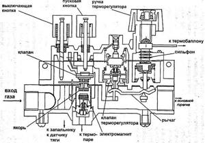
Fig. 37. Automation "Arbat"
When the thermocylinder heats up, the thermostatic liquid expands and flows through the capillary into the bellows, which expands and moves down a spring-loaded rod that interacts with the lever. The increased movement of the bellows through the lever causes the thermostatic valve to move to close - the gas supply to the main burner will decrease. If the valve closes completely, the burner will operate in the “Low flame” mode. If, during this operating mode, the water temperature continues to increase above the set value, then further impact on the spring-loaded rod from the bellows causes the bypass valve to operate, which leads to a complete shutdown of the main burner.
When the igniter goes out , the thermocouple cools, the solenoid valve is activated and the gas supply stops.
If the draft is disrupted, the bimetallic disk of the draft sensor heats up from the heat of the combustion products, bends and opens the nozzle, dumping gas from the distribution chamber, which leads to the igniter going out and the solenoid valve closing.
When you press the shutdown button, the gas supply to the main burner and igniter is immediately stopped.
⇐ Previous7Next ⇒
Recommended pages:
Use the site search: