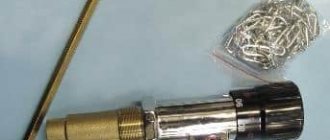
Gas burner device VESTGAZKONTROL PG-16M with automatic equipment 630 EUROSIT (Italy).
The gas burner device VESTGAZCONTROL PG-16M is used to modernize or replace gas automatics in old boilers, which allows increasing the efficiency of heating equipment by almost 20%. The gas burner device VESTGAZCONTROL PG-16M is intended for heating the coolant and (or) structural elements of heating equipment.
The device is designed for operation on natural gas in accordance with GOST 5542–87 with a pressure of 1274+100 Pa. GGU Westgazcontrol PG-16M provides economical combustion of natural gas with the ability to automatically regulate thermal power and shut off the gas supply in the event of an emergency. Automation Westgazcontrol PG-16M is equipped with an automatic control device - gas valve 630 EUROSIT (SIT, Italy).
The gas valve 630 EUROSIT does not require a power supply.
The gas valve 630 EUROSIT allows you to:
- ignition of the pilot burner using a piezoelectric element; - regulation of the coolant temperature from 40°C to 90°C; - regulation of the maximum gas flow; - regulation of the minimum gas flow; - regulation of the gas flow to the pilot burner;
and provides:— automatic maintenance of a given coolant temperature;— automatic shutdown of the device in the event of a sudden shutdown of gas;— automatic shutdown of the device in the absence of draft and during reverse draft;— the ability to operate the device at reduced gas pressure.
The use of micro-flare burners made of stainless steel in the Westgazcontrol PG-16 gas automation system ensures: - gas savings of up to 20% compared to conventional burners; - reduction in CO emissions into the atmosphere; - reduction in the intensity of soot deposition in the chimney; - reliable operation of the burner throughout its entire life. operation.
Specifications:
Gas burner device VESTGAZKONTROL PG-16M with automatic equipment 630 EUROSIT (Italy)
Multifunctional gas supply regulator with a modulating thermostat and the function of complete modulating shutdown of the main burner - 630 EUROSIT is a non-volatile device and is available in various designs and is intended for use in convectors, water heaters, boilers, grills and other gas-consuming equipment that requires precise temperature control.MAIN CHARACTERISTICS
Control knob with positions “off”, “ignition” and “temperature selection” (MS). Thermoelectric flame protection system with blocking of gas supply to the main burner after switching off (GM). Maximum gas flow setting device (RQ) or, optionally, pressure regulator (PR). Screw for setting the minimum gas flow (“by pass”). Modulation thermostat with the function of completely turning off the main burner (TN). Gas outlet to the pilot burner with gas flow adjustment screw (RQ). Inlet filter and pilot burner filter (FL). Connections for measuring gas pressure. Gas supply, optionally from the side or from below. Options for gas connections of the multifunctional regulator: pipe with external thread or pipe connection using a nut with a seal.
WORKING SCHEME
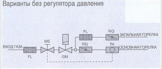
Options without pressure regulator
Options with pressure regulator
TECHNICAL DATA
The following technical data refers to standard EN 126 - “Multifunctional control devices for gas appliances”.
• Connections - Rp 1/2 ISO 7 • Any operating position • Gas used (families) I, II and III • Maximum gas inlet pressure 50 mbar • Regulator setting range 3..18 mbar • Operating ambient temperature 0..80 ° C • Pressure regulator (optional) Class C • Torsional and bending stability Group 2 • Thermoelectric protection system (when using SIT thermocouples of the 200 or 290 series) - ignition time < 10 sec. — reset time < 60 sec. — estimated number of ignition cycles 10,000 • Manual reset system estimated number of reset cycles 10,000
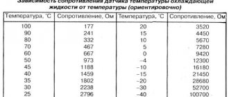
CHARACTERISTICS
The characteristics of the thermostat with the function of completely turning off the main burner are shown in the following table and graph:
GAS CONSUMPTION
Gas flow Q (15 °C, 1013.25 mbar) as a function of the pressure difference before and after the valve, control knob in position 7, cold thermal cylinder.
Adjustable flow Q (15 °C, 1013.25 mbar) as a function of the pressure difference before and after the valve, control knob in position 7, cold bulb in accordance with the EN 88 standard
EXPLOITATION
Ignition of the pilot burner
Make sure the control knob is in the "off" position, turn the control knob to the Press the control knob position and light the pilot, holding the control knob for a few seconds (Fig. 1). Release the control knob and check that the pilot burner is lit (Fig. 2). If the pilot burner goes out, repeat the ignition procedure.
Temperature selection
Turn the control knob to the position corresponding to the selected temperature (Fig. 3).
Duty position
When the control knob is turned from the position corresponding to the selected temperature to the position, the main burner goes out, but the pilot burner remains lit.
Turning off the boiler
Turn the control knob to the “Off” position (Fig. 4).
● Attention
Restarting the device after an emergency shutdown can be done approximately 60 seconds after the flame control device is turned off. Turning the control knob from the “Pilot” position is possible only after the flame control thermocouple has cooled. When cooled, the thermocouple stops producing thermoEMF, which holds the thermoelectric flame control device in the blocking position.
INSTALLATION
«630 EUROSIT
» complies with current safety standards. The installation of a multifunctional regulator on gas-consuming equipment must be carried out in accordance with the specific requirements that exist for this equipment. In particular, compliance with the requirements regarding the thermoelectric protection system and, if present, the pressure stabilizer must be checked. All installation and configuration operations must be performed by qualified personnel. The multifunction controller is not intended for outdoor use.
MECHANICAL CONNECTIONS
General recommendations
Do not damage the sealing parts. Do not loosen the assembly screws. Don't remove the shortcuts. Avoid shocks (impacts, falls, etc.). Remove dust caps only during installation. Do not exceed the recommended tightening torque. Make sure gas flow is in the direction indicated by the arrow on the regulator body. Take care to ensure that foreign materials do not enter the valve during installation. In particular, check the cleanliness of the inlet and outlet pipes. Do not subject the multi-function controller to bending moment exceeding 35 Nm and torque exceeding 25 Nm. Use only special wrenches when making connections. The regulator has 3 pairs of mounting holes.
● Warning
Some versions of the multifunction gas regulator are supplied without certain parts. Therefore, when installing regulators, it is necessary to check the presence of the following components: • screw for adjusting the minimum gas flow (3) (Fig. A) • screw for adjusting the maximum gas flow (5) (Fig. A) or, optionally, a pressure regulator (2′) (Fig. A')
If not, install as follows:
• check the correctness of the accessory part code • insert the minimum gas flow adjustment screw into the hole (14), the maximum gas flow adjustment screw or pressure regulator into the hole (15) • insert the components and tighten them completely. Tightening torques: - adjustment screws 7 Nm - pressure regulator: 1 Nm
Gas connection
Use gas pipe with Rp 3/8 ISO 7 thread. Tightening torque: 25 Nm. It is possible to connect a 012 mm tube using an O-ring and a nut (codes 0.958.025 and 0.957.007). Tightening torque 15 Nm. The valve has two inlet ports (10) and (12) and two outlet ports (11) and (13). Holes that have not been used must be closed with plugs (code 0.972.058). Tightening torque 7 Nm.
Pilot burner connection
output (8) Tubes with diameters of Ø 4 mm, Ø 6 mm or Ø 1/4″ can be used. Use nuts and o-rings of the appropriate size. Tightening torque 7 Nm.
● Warning
After completing the work, check the connections for leaks.
INSTALLATION AND ADJUSTMENT PARAMETERS
All adjustments must be made in accordance with the specific requirements of the equipment to which the multifunction controller is installed. Check the inlet and outlet pressure using the gas pressure fittings (b) and (7). After measuring the pressure, carefully plug the fittings with the appropriate screws. Recommended tightening torque: 2.5 Nm.
Setting the maximum and minimum gas flow
These settings are made with a cold bulb.
Setting the maximum gas flow (version without pressure regulator) - fig. A.
Turn the control knob (4) to position 7. Fully tighten the adjustment screw (2), and then gradually turn it out until the required gas flow is achieved.
● Warning
Once fully tightened, do not unscrew the screw more than two turns.
Disabling the maximum gas flow function
Fully tighten the adjustment screw (2), and then turn it out two turns and lock it. Disabling can also be done by replacing the adjustment screw (2) with a plug (code 0.972.057). In this case, the plug must be completely screwed in.
Setting the maximum gas flow (version with pressure regulator) - fig. A'
Turn the control knob to position 7. When you turn the adjustment screw (2′) clockwise, the gas flow increases.
Disabling the pressure regulator function
Turn the adjustment screw (2′) fully clockwise.
Setting the minimum gas flow
Slowly turn the control knob clockwise to the minimum power position (close to the main burner off position). When turning the adjustment screw (3) counterclockwise, the gas flow increases. It is also possible to use screws with calibrated holes (optional) instead of screws for adjusting the maximum and minimum gas flow. In this case, the screws must be tightened with a tightening torque of 7 Nm.
Setting the gas supply to the pilot burner
When turning the screw (5) clockwise, the gas flow decreases.
Disabling the gas supply setting function for the pilot burner
Fully tighten the adjustment screw (5′) and then back it out two turns until it locks.
Changing the type of gas
Check whether the equipment on which the multifunction regulator is installed can use the appropriate type of gas. Set the gas pressure at the regulator outlet given in the equipment manufacturer's instructions in accordance with the previous instructions. For gas of the III family: disable the function of setting the maximum gas flow or pressure regulator; disable the function of adjusting the gas flow to the pilot burner.
● Important
After completing all adjustments and adjustments, check the tightness of the seals and the correct operation of the equipment. Flame separation or breakthrough is strictly prohibited at the corresponding maximum and minimum gas pressure. After completing the adjustment work, secure the seals and/or adjustment screws with paint.
REPAIR
Only one type of repair work is allowed - replacing the magnetic unit. This operation should only be performed by qualified personnel in accordance with the spare parts installation instructions.
PARTS AND ACCESSORIES
Screws with a calibrated hole for maximum gas flow Screws with a calibrated hole for minimum gas flow Pressure regulator 3-18 mbar - 0.907.630
3/8″ plug for unused gas connection hole - 0.972.058
Fitting for connecting the gas supply tube to the pilot burner. Tube Diameter:
Ø 4 mm – 0.958.030 Ø 6 mm – 0.958.031 Ø 1/4″ – 0.958.032
Sand-colored cover with screw - 0.973.044 Sand-colored cover with screw and piezo igniter - 0.073.954 Remote control adapter - 0.997.209
Other accessories available upon request
DIMENSIONS
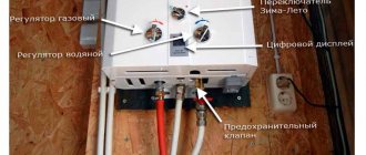
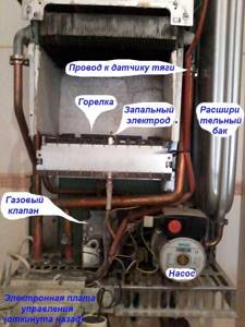
Wall unit electronics
A special feature of these heat generators is electronic control of the processes of ignition, combustion and maintenance of coolant temperature. That is, wall-mounted gas boilers (and some floor-standing ones) are equipped with energy-dependent automation powered by electricity.
An automatic gas boiler was created for maximum convenience for owners of apartments and private houses. To start the heater, just press 1 button and set the desired temperature. Let us briefly describe the operating algorithm of the unit and the elements involved in it:
- After these startup steps, the heat generator controller collects sensor readings: coolant and air temperature, gas and water pressure in the system, and checks the presence of draft in the chimney.
- If everything is in order, the electronic board supplies voltage to the electromagnetic gas valve and at the same time a discharge to the ignition electrodes. The wick is missing.
- The main burner ignites and gives full power in order to heat the coolant as quickly as possible. Its operation is monitored by a special flame sensor. The controller includes a built-in circulation pump.
- When the coolant temperature approaches the set threshold, which is recorded by the overhead sensor, the combustion intensity will decrease. Staged burners switch to low power mode, and modulating burners smoothly reduce the fuel supply.
- Having reached the heating threshold, the electronics will shut off the gas. When the sensor detects cooling of the water in the system, automatic ignition and heating will be repeated.
The instructions for the wall-mounted gas boiler indicate that the unit is designed to operate in a closed heating system, so the automation monitors the water pressure. If it drops below the permissible limit (0.8-1 Bar), the burner will go out and will not light until the problem is corrected.
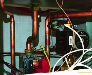
Many imported boilers operate according to an energy-dependent scheme, for example, Buderus Logano, Viessmann and so on. How the installation of electronic gas equipment occurs, the master will tell you in an accessible language in the video:
Automation eurosit 630 faults
| | Home | Instructions | 630 EUROSIT | |
Multifunctional gas supply regulator with a modulating thermostat and the function of complete modulating shutdown of the main burner - 630 EUROSIT is a non-volatile device and is available in various designs and is intended for use in convectors, water heaters, boilers, grills and other gas-consuming equipment that requires precise temperature control.
Control knob with positions “off”, “ignition” and “temperature selection” (MS). Thermoelectric flame protection system with blocking of gas supply to the main burner after switching off (GM). Maximum gas flow setting device (RQ) or, optionally, pressure regulator (PR). Screw for setting the minimum gas flow (“by pass”). Modulation thermostat with the function of completely turning off the main burner (TN). Gas outlet to the pilot burner with gas flow adjustment screw (RQ). Inlet filter and pilot burner filter (FL). Connections for measuring gas pressure. Gas supply, optionally from the side or from below. Options for gas connections of the multifunctional regulator: pipe with external thread or pipe connection using a nut with a seal.
Options without pressure regulator
Options with pressure regulator
The following technical data refers to standard EN 126 - “Multifunctional control devices for gas appliances”.
• Connections - Rp 1/2 ISO 7 • Any operating position • Gas used (families) I, II and III • Maximum gas inlet pressure 50 mbar • Regulator setting range 3..18 mbar • Operating ambient temperature 0..80 ° C • Pressure regulator (optional) Class C • Torsional and bending resistance Group 2 • Thermoelectric protection system (when using SIT thermocouples 200 or 290 series) - ignition time ● Attention Restarting the device after an emergency shutdown can be done after approximately 60 seconds after switching off the flame control device. Turning the control knob from the “Pilot” position is possible only after the flame control thermocouple has cooled. When cooled, the thermocouple stops producing thermoEMF, which holds the thermoelectric flame control device in the blocking position.
«630 EUROSIT
» complies with current safety standards. The installation of a multifunctional regulator on gas-consuming equipment must be carried out in accordance with the specific requirements that exist for this equipment. In particular, compliance with the requirements regarding the thermoelectric protection system and, if present, the pressure stabilizer must be checked. All installation and configuration operations must be performed by qualified personnel. The multifunction controller is not intended for outdoor use.
Do not damage the sealing parts. Do not loosen the assembly screws. Don't remove the shortcuts. Avoid shocks (impacts, falls, etc.). Remove dust caps only during installation. Do not exceed the recommended tightening torque. Make sure gas flow is in the direction indicated by the arrow on the regulator body. Take care to ensure that foreign materials do not enter the valve during installation. In particular, check the cleanliness of the inlet and outlet pipes. Do not subject the multi-function controller to bending moment exceeding 35 Nm and torque exceeding 25 Nm. Use only special wrenches when making connections. The regulator has 3 pairs of mounting holes.
Some versions of the multifunction gas regulator are supplied without certain parts. Therefore, when installing regulators, it is necessary to check the presence of the following components: • screw for adjusting the minimum gas flow (3) (Fig. A) • screw for adjusting the maximum gas flow (5) (Fig. A) or, optionally, a pressure regulator (2′) (Fig. A')
If not, install as follows:
• check the correctness of the accessory part code • insert the minimum gas flow adjustment screw into the hole (14), the maximum gas flow adjustment screw or pressure regulator into the hole (15) • insert the components and tighten them completely. Tightening torques: - adjustment screws 7 Nm - pressure regulator: 1 Nm
Use gas pipe with Rp 3/8 ISO 7 thread. Tightening torque: 25 Nm. It is possible to connect a 012 mm tube using an O-ring and a nut (codes 0.958.025 and 0.957.007). Tightening torque 15 Nm. The valve has two inlet ports (10) and (12) and two outlet ports (11) and (13). Holes that have not been used must be closed with plugs (code 0.972.058). Tightening torque 7 Nm.
Pilot burner connection
output (8) Tubes with diameters of Ø 4 mm, Ø 6 mm or Ø 1/4″ can be used. Use nuts and o-rings of the appropriate size. Tightening torque 7 Nm.
After completing the work, check the connections for leaks.
INSTALLATION AND ADJUSTMENT PARAMETERS
All adjustments must be made in accordance with the specific requirements of the equipment to which the multifunction controller is installed. Check the inlet and outlet pressure using the gas pressure fittings (b) and (7). After measuring the pressure, carefully plug the fittings with the appropriate screws. Recommended tightening torque: 2.5 Nm.
Setting the maximum and minimum gas flow
These settings are made with a cold bulb.
Setting the maximum gas flow (version without pressure regulator) - fig. A.
Turn the control knob (4) to position 7. Fully tighten the adjustment screw (2), and then gradually turn it out until the required gas flow is achieved.
● Warning
Once fully tightened, do not unscrew the screw more than two turns.
Disabling the maximum gas flow function
Fully tighten the adjustment screw (2), and then turn it out two turns and lock it. Disabling can also be done by replacing the adjustment screw (2) with a plug (code 0.972.057). In this case, the plug must be completely screwed in.
Setting the maximum gas flow (version with pressure regulator) - fig. A'
Turn the control knob to position 7. When you turn the adjustment screw (2′) clockwise, the gas flow increases.
Disabling the pressure regulator function
Turn the adjustment screw (2′) fully clockwise.
Setting the minimum gas flow
Slowly turn the control knob clockwise to the minimum power position (close to the main burner off position). When turning the adjustment screw (3) counterclockwise, the gas flow increases. It is also possible to use screws with calibrated holes (optional) instead of screws for adjusting the maximum and minimum gas flow. In this case, the screws must be tightened with a tightening torque of 7 Nm.
Setting the gas supply to the pilot burner
When turning the screw (5) clockwise, the gas flow decreases.
Disabling the gas supply setting function for the pilot burner
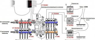
Remote control of the boiler using multifunctional thermostats
When the house has an outdated heat supply system without any hint of the ability to connect electronic units, there are no three-way valves and other automatic equipment - you can buy universal thermostats on the market that can easily be combined into a branched system into many zones with the ability to control heating via the Internet.
The kit of such equipment includes an electronic controller, where all settings for each zone take place.
It doubles as a WI-FI transmitter-receiver and through this channel “communicates” with electronic thermostats installed on each battery.
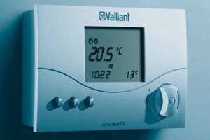
Remote control of the boiler using a Vaillant programmer
It has a separate channel connection with the boiler shutdown unit. Heating parameters can be changed either on the controller itself manually or via the Internet.
Types of gas boiler draft sensor
There are two types of gas boilers. The first is boilers with natural draft, and the second is equipment with forced draft. Each type needs its own type of equipment.
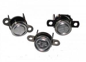
An open combustion chamber combined with properly selected chimneys guarantees normal natural draft. The sensors for these boilers contain a bimetallic strip connected to an electrical contact. The operating principle is quite simple.
The closed combustion chamber, with the help of blowing devices, detects the forced draft equipment, which contains a sensor, the so-called pneumatic relay. The device controls the operation of the fan and the exhaust rate of combustion gases. Structurally, the device consists of a membrane that bends during normal draft under the pressure of flue gases. As soon as the gas pressure drops below normal, the membrane reduces deflection and the contacts open and the gas valve closes. Sensors ensure normal operation of the heating device. The device is a fundamental element of boiler protection, because with low draft, the process of re-drafting flue gases is possible and combustion products leave the boiler not towards the street, but go into the room.
The most common breakdowns in the control unit
Since the control unit is a whole system, a failure can occur from any deviation of a component of this system. The most common malfunctions and their causes:
- the burner went out - air got into the gas pipeline;
- heating problems - poor gas supply, lack of oxygen;
- boiler overheating - closed contacts, prolonged operation at high temperatures, factory defective sensors;
- breakdown of the pneumatic relay (draft sensor) - incorrect connection, fan breakdown, incorrect smoke exhaust system;
- breakdown of the temperature sensor - incorrect connection of contacts, short circuit, overheating of the board;
- breakdown of the pressure switch - low water pressure in the pipes, defective contacts in the circuit board.
Most of these problems are easily fixed, even described in the instructions, but some require the intervention of a specialist.
You should not replace sensors or other parts yourself - this can be dangerous.
Conclusions and useful video on the topic
On the presented video you will find brief instructions for installing a gas boiler equipped with an automatic Eurosit system.
A modern gas boiler is a rather complex design that provides many useful functions. The automation of most models greatly facilitates their operation, taking over the control of the mechanisms and monitoring their operation. .
This significantly increases the level of safety during the operation of the heating system, and also increases its efficiency by selecting the optimal mode.
Do you need to adjust the automation of your gas boiler? Do you want to tackle this problem yourself and want to clarify some points? Don’t be shy – ask your questions under this article, and our experts will try to help you.
Or have you successfully adjusted the automation and want to share your experience with other users? Write your tips, add photos depicting the main points - your recommendations will be very useful to other owners of the same boiler.
Functions and principle of operation of security automation
In accordance with regulatory documents, automation equipment for boiler installations must stop their operation by cutting off the fuel supply in the following situations:
- the draft in the chimney is insufficient and there is a danger of burning;
- the gas pressure in the supply pipeline is too low or, conversely, too high;
- The flame on the igniter went out.
The listed situations can lead to the main burner going out and the room becoming gassed, which is unacceptable. For this reason, safety automatics for gas boilers must be installed on all old-style boilers where it was not provided by the manufacturer. Although it is often cheaper to replace a heater than to purchase and install automation on an old one. In addition to preventing gas contamination of the room or fumes, its functions also include maintaining the temperature of the coolant at a certain level specified by the user.
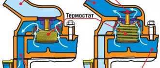
To understand how the automation of a gas boiler works, let’s briefly analyze its structure. It should be noted that both foreign and Russian manufacturers use the same operating principle in their products, although the design of the devices may differ significantly. Automatic gas valves from Italian manufacturers are traditionally considered the simplest and most reliable, which is why they are most common.
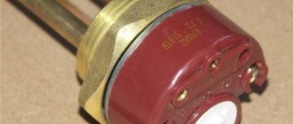
A prominent representative of such gas appliances is the Italian automatic SIT, or rather, its most popular modification 630 EUROSIT, whose device is shown below.
All structural elements are placed in one housing, to which gas pipelines are connected. In addition, a capillary tube from draft and temperature sensors (thermocouples), a gas supply line for the igniter and a cable from the piezoelectric element are connected to the device. Inside there is a shut-off solenoid valve, whose normal state is “closed,” as well as a gas pressure regulator and a spring valve.
Any automatic gas boiler equipped with a combined gas valve EUROSIT or another is started manually. Initially, the fuel path is blocked by an electromagnetic valve, which opens by pressing the adjusting washer, after which the fuel fills the chambers of the device and goes through a small gas pipeline to the igniter. While holding the washer, press the button of the piezoelectric device and ignite the igniter, heating the temperature-sensitive element for 10-30 seconds. This, in turn, generates a voltage that keeps the solenoid valve open, after which the adjusting washer can be released.
Then everything is simple, we turn the washer to the required division and thereby open access of fuel to the burner, which is independently ignited by the igniter. Since the automation of gas boilers is designed to maintain the set temperature of the coolant, human intervention is no longer required. The principle here is this: when heated, the medium in the capillary system expands and acts on the spring valve, closing it when it reaches a high temperature. The burner goes out until the thermocouple cools down and the gas supply resumes. You can study the operation of Italian SIT automation in detail by watching the video.
Automation Eurosit 630 (Eurosit 630)
The Eurosit gas valve is one of the most used.
It can be found on both domestic and imported boilers. Main advantages: multifunctionality of the gas supply regulator, modulation thermostat and the function of full modulation switching on the main burner. It works both from liquefied fuel cylinders and from a gas tank, without the use of electricity. Used in various types of gas-consuming equipment that require precise temperature control. Basic principles of operation of Eurosit 630 automation.
Ignition of the pilot burner.
- Check that the knob position matches the “off” icon.
- Move the control knob to the “asterisk” position.
- Keep the control knob pressed for a few seconds. Then release and make sure the pilot burner turns on. If the pilot burner goes out, repeat step 3.
Temperature selection.
Use the control knob to set the temperature. The gas will begin to flow into the main burner, where it will be ignited using the pilot burner.
Power modulation.
The thermostatic system regulates gas flow and gas pressure in the main burner depending on the system capillary sensor. The colder the sensor, the greater the power and vice versa. The graph schematically shows how the power changes from maximum to minimum and then until the burner is completely turned off.
Duty position.
Move the control knob from the set temperature to “asterisk”. The main burner will go out, but the pilot burner will remain lit.
Shutdown.
Set the knob to the off position. The valve will close completely, but the thermoelectric protection magnet will remain temporarily activated until the thermocouple sensor cools down. During this period of time, restarting of the thermoelectric system is mechanically prevented. The function is called "interlog". It ensures ventilation of the combustion chamber before the next burner start-up.
Automatic 630 EUROSIT. Adjustment.
Today, the Rostov Boiler Equipment Plant CJSC Rostovgazoapparat produces Siberia boilers, widely known in our country. The author of these lines had the honor of installing such a boiler in his own home. Everything would be fine, but in severe frosts problems with the insufficient power of this device began to appear. At first, I was guilty of power, since the area of the heated house is 95 square meters. m. and the declared boiler power is 11.6 kW. Naturally, the power reserve is small, since the recommended reserve should be + 30% of the area of the house. My boiler must be at least 12.5 kW. that is, for heating 125 sq.m. Now a brief background for buyers of Siberia boilers.
WARNING Some versions of the multifunction gas regulator are supplied without certain parts. Therefore, when installing regulators, it is necessary to check the presence of the following components:• minimum gas flow adjustment screw 3 (Fig. A)• maximum gas flow adjustment screw 2 (Fig. A) or, optionally, pressure regulator 2' (Fig. A*) If not, proceed as follows:• check that the accessory code is correct• insert the minimum gas flow adjustment screw into hole 14 (Fig. B), the maximum gas flow adjustment screw or pressure regulator into hole 15 (Fig. B)• insert the accessories and tighten completely. Tightening torques: - adjustment screws 7 Nm - pressure regulator: 1 Nm Gas connection Use a gas pipe with Rp 3/8 ISO 7 thread. Tightening torque: 25 Nm. It is possible to connect a tube diameter of 12 mm using an o-ring and a nut (codes 0.958.025 and 0.957.007). Tightening torque 15 Nm. The valve has two inlet ports 10 and 12 (Figure D) and two outlet ports 11 and 13 (Figure D). Holes that have not been used must be closed with plugs (code 0.972.058). Tightening torque 7 Nm. Connecting the pilot burner, pin 8 (Fig. D) Tubes with diameters of 4 mm, 6 mm or 1/4″ can be used. Use nuts and flares of the correct size
Tightening torque 7 Nm. ATTENTION After completing work, check the connections for leaks
Setting the maximum and minimum gas flow
These settings are made with a cold bulb.
Setting the maximum gas flow
(version without pressure regulator) - (
Fig. A
). Turn control knob
4
to position
7
.
Fully tighten the adjustment screw 2
, and then gradually turn it out until the required gas flow is achieved.
WARNING
Once fully tightened, do not back out the screw more than
two
turns.
Disabling the maximum gas flow function
Fully tighten the adjustment screw
2
, and then turn it out two turns and lock it.
Disabling can also be done by replacing adjustment screw 2
with a plug (code 0.972.057). In this case, the plug must be completely screwed in.
Setting the maximum gas flow
(version with pressure regulator) - (
fig. A*
). Turn the control knob to position
7
.
When turning the adjustment screw 2' clockwise (VERSION WITH PRESSURE REGULATOR)
, the gas flow increases.
Disabling the pressure regulator function
2'
adjustment screw fully clockwise.
Setting the minimum gas flow
Slowly turn the control knob clockwise to the minimum power position (close to the main burner off position).
When turning adjustment screw 3
counterclockwise, the gas flow increases.
It is also possible to use screws with calibrated holes (optional) instead of screws for adjusting the maximum and minimum gas flow. In this case, the screws must be tightened with a tightening torque of 7 Nm.
Setting the gas supply to the pilot burner
When screw
5
clockwise, gas consumption decreases.
ATTENTION After completing all adjustments and adjustments, check the seals for tightness and proper operation of the equipment. Flame separation or breakthrough is strictly prohibited at the maximum and minimum gas pressure, respectively.
After completing the adjustment work, secure the seals and/or adjustment screws with paint.
I present questions and answers from the old site; if you don’t find anything useful for yourself, write below in the comments.
Automatic 630 EUROSIT
Automation for boilers 630 eurosit. Do-it-yourself setup and adjustment of the 630 eurosit automation at home.
How_to_set up_automation_evrosit_630
| | Home | Instructions | 630 EUROSIT | |
Multifunctional gas supply regulator with a modulating thermostat and the function of complete modulating shutdown of the main burner - 630 EUROSIT is a non-volatile device and is available in various designs and is intended for use in convectors, water heaters, boilers, grills and other gas-consuming equipment that requires precise temperature control.
Control knob with positions “off”, “ignition” and “temperature selection” (MS). Thermoelectric flame protection system with blocking of gas supply to the main burner after switching off (GM). Maximum gas flow setting device (RQ) or, optionally, pressure regulator (PR). Screw for setting the minimum gas flow (“by pass”). Modulation thermostat with the function of completely turning off the main burner (TN). Gas outlet to the pilot burner with gas flow adjustment screw (RQ). Inlet filter and pilot burner filter (FL). Connections for measuring gas pressure. Gas supply, optionally from the side or from below. Options for gas connections of the multifunctional regulator: pipe with external thread or pipe connection using a nut with a seal.
Options without pressure regulator
Options with pressure regulator
The following technical data refers to standard EN 126 - “Multifunctional control devices for gas appliances”.
• Connections - Rp 1/2 ISO 7 • Any operating position • Gas used (families) I, II and III • Maximum gas inlet pressure 50 mbar • Regulator setting range 3..18 mbar • Operating ambient temperature 0..80 ° C • Pressure regulator (optional) Class C • Torsional and bending resistance Group 2 • Thermoelectric protection system (when using SIT thermocouples 200 or 290 series) - ignition time ● Attention Restarting the device after an emergency shutdown can be done after approximately 60 seconds after switching off the flame control device. Turning the control knob from the “Pilot” position is possible only after the flame control thermocouple has cooled. When cooled, the thermocouple stops producing thermoEMF, which holds the thermoelectric flame control device in the blocking position.
«630 EUROSIT
» complies with current safety standards. The installation of a multifunctional regulator on gas-consuming equipment must be carried out in accordance with the specific requirements that exist for this equipment. In particular, compliance with the requirements regarding the thermoelectric protection system and, if present, the pressure stabilizer must be checked. All installation and configuration operations must be performed by qualified personnel. The multifunction controller is not intended for outdoor use.
Do not damage the sealing parts. Do not loosen the assembly screws. Don't remove the shortcuts. Avoid shocks (impacts, falls, etc.). Remove dust caps only during installation. Do not exceed the recommended tightening torque. Make sure gas flow is in the direction indicated by the arrow on the regulator body. Take care to ensure that foreign materials do not enter the valve during installation. In particular, check the cleanliness of the inlet and outlet pipes. Do not subject the multi-function controller to bending moment exceeding 35 Nm and torque exceeding 25 Nm. Use only special wrenches when making connections. The regulator has 3 pairs of mounting holes.
Some versions of the multifunction gas regulator are supplied without certain parts. Therefore, when installing regulators, it is necessary to check the presence of the following components: • screw for adjusting the minimum gas flow (3) (Fig. A) • screw for adjusting the maximum gas flow (5) (Fig. A) or, optionally, a pressure regulator (2′) (Fig. A')
If not, install as follows:
• check the correctness of the accessory part code • insert the minimum gas flow adjustment screw into the hole (14), the maximum gas flow adjustment screw or pressure regulator into the hole (15) • insert the components and tighten them completely. Tightening torques: - adjustment screws 7 Nm - pressure regulator: 1 Nm
Use gas pipe with Rp 3/8 ISO 7 thread. Tightening torque: 25 Nm. It is possible to connect a 012 mm tube using an O-ring and a nut (codes 0.958.025 and 0.957.007). Tightening torque 15 Nm. The valve has two inlet ports (10) and (12) and two outlet ports (11) and (13). Holes that have not been used must be closed with plugs (code 0.972.058). Tightening torque 7 Nm.
Pilot burner connection
output (8) Tubes with diameters of Ø 4 mm, Ø 6 mm or Ø 1/4″ can be used. Use nuts and o-rings of the appropriate size. Tightening torque 7 Nm.
After completing the work, check the connections for leaks.
INSTALLATION AND ADJUSTMENT PARAMETERS
All adjustments must be made in accordance with the specific requirements of the equipment to which the multifunction controller is installed. Check the inlet and outlet pressure using the gas pressure fittings (b) and (7). After measuring the pressure, carefully plug the fittings with the appropriate screws. Recommended tightening torque: 2.5 Nm.
Setting the maximum and minimum gas flow
These settings are made with a cold bulb.
Setting the maximum gas flow (version without pressure regulator) - fig. A.
Turn the control knob (4) to position 7. Fully tighten the adjustment screw (2), and then gradually turn it out until the required gas flow is achieved.
● Warning
Once fully tightened, do not unscrew the screw more than two turns.
Disabling the maximum gas flow function
Fully tighten the adjustment screw (2), and then turn it out two turns and lock it. Disabling can also be done by replacing the adjustment screw (2) with a plug (code 0.972.057). In this case, the plug must be completely screwed in.
Setting the maximum gas flow (version with pressure regulator) - fig. A'
Turn the control knob to position 7. When you turn the adjustment screw (2′) clockwise, the gas flow increases.
Installation recommendations
A simple automated unit for monitoring and controlling a heating system of the XITAL type can be installed with your own hands if you carefully understand the operating instructions. Mounting the device and installing the sensors is not particularly difficult, as is their connection. The included cables are long enough to carry the sensors throughout your home. But there are nuances that must be taken into account when organizing heating control.

The first is the presence of good GSM coverage at your place of residence. It happens that in one place there is coverage from several cellular operators, but none of them works reliably. In this case, KCITAL is equipped with two slots for SIM cards to duplicate messages. The second caveat is that before inserting the SIM card into the slot, you must contact the operator and disable the sending of any advertising content in the form of SMS. Such messages arriving at the device number may cause malfunctions in its operation.
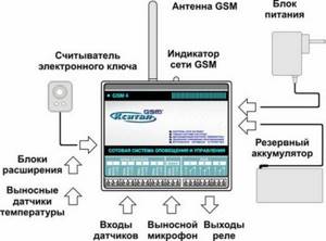
The same recommendations can be given regarding devices that interact with the owner via the Internet. The cable connected to the LAN input should not come from a router or modem powered by a 220 V network. Otherwise, if there is a power outage, the communication channel will also be lost. The devices themselves must always have their own battery, which can ensure their operation for at least 3 days. Detailed recommendations for installing XITAL can be obtained by watching the video:
Elements of safety and comfortable operation
The group of automatic devices for boilers includes many elements that can be divided into two large groups: mechanisms that ensure safe operation, and devices that facilitate comfortable operation of the boiler.
The following parts are responsible for safe operation:
- thermostat;
- draft and flame control sensors;
- safety valve.
The flame control sensor consists of a thermocouple and an electromagnetic gas valve that shuts off or turns on the gas supply.
The flame temperature regulator ( thermostat ) maintains the required temperature of the coolant and also provides protection against overheating. This module turns the boiler on or off as soon as the coolant reaches a critical point (maximum or minimum).
The draft control module stops gas supply to the burner as soon as the location of the bimetallic plate changes due to increased temperature (it bends when heated, blocking the pipe through which the fuel is supplied).
We examined temperature, draft, pressure and flame sensors in more detail in this article.
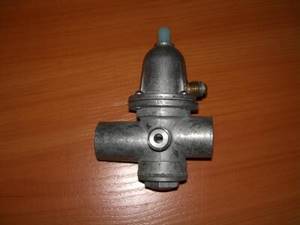
The safety valve is used to regulate, distribute and shut off the gas flow
In a heating system, a safety valve is an integral component of pipeline fittings, which is important in controlling the volume of coolant involved in the circuit.
The hole in the valve through which gaseous fuel moves is called the seat. To turn off the device, you need to close it with a disk or piston.
Depending on the number of operating positions, gas valves can be one-, two- and three-stage, as well as modeling:
- Single-stage devices have only two operating positions: on/off.
- The two-stage device is equipped with one input and two outputs, and the valve opens when it is turned to an intermediate position, due to which the switching occurs more smoothly.
- A three-stage device is equipped with boilers that have two power levels.
- Modulating valves are used to smoothly change the power rating of devices.
Automation, used for convenience, includes options that are usually performed by users of heating systems. These include auto-ignition of the burner, self-diagnosis, selection of the optimal operating mode, and others.
Types of volatile systems and operating principles
In order to avoid dangerous situations, it is recommended to purchase automatic equipment for a gas boiler. It is necessary to close and open the valve electronically. This happens after the temperature sensor gives a signal.
Devices that regulate the temperature in the house and ensure safety include:
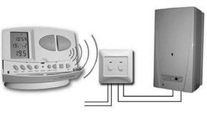
- The daily programmer can program all operations of the heating boiler for 24 hours. After a day has passed, the cycle will repeat. You can connect the programmer to the heating boiler wirelessly via radio or wired. Using a two-wire cable, you can connect a daily programmer from Saunier Duval, model ExaCONTROL. It is necessary for time programming of the temperature in the circuit for heating water and the temperature of the coolant in the heating circuit.
- The room thermostat is connected to the gas boiler using a cable. Such a device works on a simple principle: after the temperature reaches the required level, a signal is sent to the gas supply valve, then the boiler turns off. If the temperature drops, the boiler automatically turns on. The electromechanical thermostat SEITRON TAM011MI is produced on the basis of a membrane block filled with gas. The thermostat can be controlled by a temperature sensor. If the temperature has become optimal, the sensor closes or opens the contacts, thus turning the boiler on or off.
- Weekly wireless programmer. Consider the Auratin 2025 model, which can work between a receiver and a transmitter at a distance. If there are concrete walls, then the distance will be 30 meters, if in open space - 300 meters. The programmer can provide a comfortable temperature in the room due to high accuracy of adjustment. It is convenient to use the device, since the display is backlit and its color can be selected. 6 programs can be configured. You can connect an external temperature sensor, as there is a special connector.
Types and principle of operation of automation for boilers
This definition means a system of actuating and control devices aimed at maintaining specified modes, as well as promptly responding to emergency situations.
This ensures the safe use of boilers with minimal human involvement in the processes occurring in the device.

The design of gas boilers includes various types of automatic devices (electronic and mechanical) that are designed to maintain efficient, safe operation
All automation used for the correct functioning of heating devices can be divided into two fundamental groups:
- autonomous, not dependent on external power supply;
- devices that require an external source of electrical current to operate.
Let's look at each group of devices in detail.
How do energy-dependent devices function?
Such systems are complex electronic units that require electricity to operate.
At the same time, these devices allow you to regulate the fuel supply and the degree of heating by turning off or opening the tap, which helps save heating costs.

The operation of the electronic system is carried out on the basis of information transmitted by sensors to the control unit. After analyzing and processing the data on the controller and microprocessor, the commands are sent to the boiler drives
Problems solved by automatic devices:
- opening/closing the gas supply system valve;
- starting the device in automatic mode;
- preset or emergency shutdown of the boiler;
- adjusting the burner flame level using the existing temperature sensor;
- displaying data on the screen for visual reading (air temperature, water heating level, etc.).
In addition, modern automatic devices can have a number of additional functions that greatly facilitate the operation of boilers.
These include:
- management of equipment operation and monitoring of its functioning;
- protection of the heating system from malfunctions of the three-way valve;
- protection of equipment from freezing (if the temperature in the room suddenly drops, the device automatically starts the boiler into operation);
- self-diagnosis, which allows you to detect defects in components and parts, as well as identify malfunctions in the functioning of components. This option allows you to timely identify a malfunction that could lead to a serious breakdown requiring major repairs or a complete replacement of the boiler.
At the same time, reliable and stable operation of electronic automation devices for gas boilers can only be carried out under certain conditions.
Namely:
- no power surges;
- strict adherence to the recommended temperature regime;
- no problems associated with long service life.
If these rules are violated, high-tech devices can quickly fail.
There is a wide range of such automation on the market, which may involve programming or do without it. Such devices include the devices listed below.
Thermostat for measuring room temperature
The air temperature measurement sensor is located in the room, but is connected by cable to a boiler located in this or another room. The device not only monitors the heating level of the room, but also regulates the operation of the heating device.
As soon as the temperature drops below the designated level, the thermal device sends a signal to the boiler, upon receiving which the heating equipment automatically starts working.
Separate control units provide the ability to connect a temperature sensor located in the room. In this case, the set temperature will be automatically maintained in the heated space
When a comfortable level of air temperature in the device is reached, the valve closes, after which the operation of the boiler, and, consequently, the heating of the room stops, which helps to save fuel.
Our other article contains detailed information about the types and connection diagrams of a thermostat for a heating boiler.
Daily programmer for 24 hours
Like a regular thermostat, the device regulates the operating mode of a gas boiler, but has expanded capabilities.
Using this device, you can set a program for the operation of heating equipment for 24 hours, providing different levels of heating during certain periods of the day (for example, lowering the temperature in rooms at night or when people are unoccupied).
Most devices provide automatic repetition of the cycle, and to change it, you need to change the program. Connecting such a device can occur either using a cable or through a special radio channel.
Long term weekly programmer
Unlike the device described above, the weekly device allows you to schedule the operation of the boiler in advance for seven days at once.
Devices of this type, as a rule, provide several different modes, and it is also possible to create your own programs for the operation of heating devices.
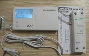
Easy to program, the Auraton-2025 device has 3 factory and 7 user modes that allow you to optimally adjust the air temperature. Light sensor turns off the display at night, saving energy
All data is transmitted to a backlit display, which allows you to comfortably track information. Since the range of the programmer is 30 meters or more, it can be placed in living rooms.
Operating principle of non-volatile automation
At the same time, individual boiler parts that perform the control function do not require the use of electricity.
They are adjusted manually, as well as under the influence of geometric changes that occur in mechanisms under the influence of heat.
In mechanical devices, the boiler is started by pressing the washer on the valve. As a result of this, the latter opens in forced mode, letting in fuel that goes to the igniter
Despite the large range of models with electronic equipment, options with mechanical control are also very popular.
This can be explained by several reasons:
- Democratic price. Prices for such devices are significantly lower than for fully automatic analogues.
- Ease of use. The simplicity of the non-volatile automation device used in mechanical models allows even a person who is not related to technology to quickly understand the settings.
- Reliability. Mechanical devices do not depend on power surges or complete power outages, so they can function without a stabilizer, which is desirable when working with volatile equipment.
The disadvantages of such models include lower accuracy of adjustments, as well as the need to monitor the operation of the boiler.
As for the settings, it is done manually. Each mechanical device is equipped with a temperature scale, the numbers of which indicate the maximum values (from min to max). The operating temperature is set by selecting the required mark on the gradation bar.
After starting the unit, the thermostat is responsible for its operation. The operating element of this device is a rod, which, contracting when cooled, opens the gas supply valve, and then increases in size due to the increase in temperature and shuts off the flow of blue fuel.
Using a similar process, you can also reduce or increase the heat level.
Types of gas valves
The main element of the automation system is the electromagnetic gas valve. This hydraulic device is used to regulate gas flow by transmitting electrical power to the valve coil. The core, which is connected to the valve seat, is drawn into the coil under the influence of electromagnetic forces.
The valve can be of several types depending on the operating position of the seat:
- Modulating valves are installed on gas boilers with the ability to smoothly change power.
- Single stage valves. They have only two positions: “open” and “closed”. After power is supplied, the valve takes its extreme position and the full gas consumption for which the boiler is designed occurs.
- Two-stage valves. This view can be fully opened with a time delay through an intermediate position. Thanks to this design, heating equipment starts smoothly. Single-stage and two-stage valves are used for single-stage burners only.
- Three stage valves. Such elements can be installed on devices where there are two power levels.
Advantages
Thus, we have completely disassembled the principle of operation of a heating system using an electronic or mechanical thermostat. This is a very convenient solution for several reasons:
Source
Control knob with positions “off”, “ignition” and “temperature selection” (MS). Thermoelectric flame protection system with blocking of gas supply to the main burner after switching off (GM). Maximum gas flow setting device (RQ) or, optionally, pressure regulator (PR). Screw for setting the minimum gas flow (“by pass”). Modulation thermostat with the function of completely turning off the main burner (TN). Gas outlet to the pilot burner with gas flow adjustment screw (RQ). Inlet filter and pilot burner filter (FL). Connections for measuring gas pressure. Gas supply, optionally from the side or from below. Options for gas connections of the multifunctional regulator: pipe with external thread or pipe connection using a nut with a seal.
READ Plantronics voyager edge how to connect
Options without pressure regulator
Options with pressure regulator
«630 EUROSIT
» complies with current safety standards. The installation of a multifunctional regulator on gas-consuming equipment must be carried out in accordance with the specific requirements that exist for this equipment. In particular, compliance with the requirements regarding the thermoelectric protection system and, if present, the pressure stabilizer must be checked. All installation and configuration operations must be performed by qualified personnel. The multifunction controller is not intended for outdoor use.
Do not damage the sealing parts. Do not loosen the assembly screws. Don't remove the shortcuts. Avoid shocks (impacts, falls, etc.). Remove dust caps only during installation. Do not exceed the recommended tightening torque. Make sure gas flow is in the direction indicated by the arrow on the regulator body. Take care to ensure that foreign materials do not enter the valve during installation. In particular, check the cleanliness of the inlet and outlet pipes. Do not subject the multi-function controller to bending moment exceeding 35 Nm and torque exceeding 25 Nm. Use only special wrenches when making connections. The regulator has 3 pairs of mounting holes.
Some versions of the multifunction gas regulator are supplied without certain parts. Therefore, when installing regulators, it is necessary to check the presence of the following components: • screw for adjusting the minimum gas flow (3) (Fig. A) • screw for adjusting the maximum gas flow (5) (Fig. A) or, optionally, a pressure regulator (2′) (Fig. A')
If not, install as follows:
• check the correctness of the accessory part code • insert the minimum gas flow adjustment screw into the hole (14), the maximum gas flow adjustment screw or pressure regulator into the hole (15) • insert the components and tighten them completely. Tightening torques: - adjustment screws 7 Nm - pressure regulator: 1 Nm
Pilot burner connection
output (8) Tubes with diameters of Ø 4 mm, Ø 6 mm or Ø 1/4″ can be used. Use nuts and o-rings of the appropriate size. Tightening torque 7 Nm.
After completing the work, check the connections for leaks.
INSTALLATION AND ADJUSTMENT PARAMETERS
All adjustments must be made in accordance with the specific requirements of the equipment to which the multifunction controller is installed. Check the inlet and outlet pressure using the gas pressure fittings (b) and (7). After measuring the pressure, carefully plug the fittings with the appropriate screws. Recommended tightening torque: 2.5 Nm.
Setting the maximum and minimum gas flow
These settings are made with a cold bulb.
Turn the control knob (4) to position 7. Fully tighten the adjustment screw (2), and then gradually turn it out until the required gas flow is achieved.
● Warning
Once fully tightened, do not unscrew the screw more than two turns.
Disabling the maximum gas flow function
Fully tighten the adjustment screw (2), and then turn it out two turns and lock it. Disabling can also be done by replacing the adjustment screw (2) with a plug (code 0.972.057). In this case, the plug must be completely screwed in.
READ How to connect a flash drive to a Sony xperia smartphone
Disabling the pressure regulator function
Turn the adjustment screw (2′) fully clockwise.
Setting the minimum gas flow
Slowly turn the control knob clockwise to the minimum power position (close to the main burner off position). When turning the adjustment screw (3) counterclockwise, the gas flow increases. It is also possible to use screws with calibrated holes (optional) instead of screws for adjusting the maximum and minimum gas flow. In this case, the screws must be tightened with a tightening torque of 7 Nm.
Setting the gas supply to the pilot burner
Disabling the gas supply setting function for the pilot burner
Fully tighten the adjustment screw (5′) and then back it out two turns until it locks.
Changing the type of gas
Check whether the equipment on which the multifunction regulator is installed can use the appropriate type of gas. Set the gas pressure at the regulator outlet given in the equipment manufacturer's instructions in accordance with the previous instructions. For gas of the III family: disable the function of setting the maximum gas flow or pressure regulator; disable the function of adjusting the gas flow to the pilot burner.
After completing all adjustments and adjustments, check the tightness of the seals and the correct operation of the equipment. Flame separation or breakthrough is strictly prohibited at the corresponding maximum and minimum gas pressure. After completing the adjustment work, secure the seals and/or adjustment screws with paint.
PARTS AND ACCESSORIES
Fitting for connecting the gas supply tube to the pilot burner. Tube Diameter:
Source

You are not authorized - you cannot write on the forum or view files
Page: 1
How to choose the right model
The main criterion is the specification of the model. There are devices that are suitable only for certain models of boilers from one manufacturer; they are produced as additional equipment for the boiler; information about their purpose is usually contained in the name itself. Of course, if this is possible, it is better to choose a GSM module from the same manufacturer as the boiler (it will be tailored to a specific line of models and their specifics).
But there are also universal models that are suitable for absolutely any boiler that has the appropriate terminals; it is these universal GSM modules that are discussed in the article.
Today, the choice of universal GSM modules is small (about 20-25 models), so it is difficult to identify a sufficient number of criteria. We recommend studying the most famous and successful models (see below) and choosing from them, studying the functionality and convenience of each, comparing prices
But we also recommend paying attention to criteria such as:
- The presence of an application and web interface that significantly simplifies management and allows you to see and analyze work statistics.
If the manufacturer has not provided interface examples, it is worth looking for screenshots in the image search of any search engine. An example of the web interface of ZONT modules, the interface is available in your personal account on the manufacturer’s website. - Standard equipment. Some modules are supplied with external temperature sensors, which can be placed in rooms remote from the boiler room and be guided by their measurements, which is an obvious advantage. A good option is the one with an external antenna, which allows you to seriously improve the quality of communication, and in some cases, when you move the antenna higher, you can even catch a signal that is missing on the ground floor or in the basement of a remote house.
- The capacity of the built-in battery should be at least 100-150 mAh, with these parameters it will be enough for 2-4 hours of operation of the module.