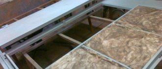
The Babington burner was originally used to heat buildings and ran on diesel fuel.
The burner's inventor, Robert Babington, patented his device in 1979, and after the patent expired, information about the invention became publicly available.
After this, many craftsmen came up with the idea of using waste oil in the burner instead of diesel fuel.
This is how the modern burner design arose, which is still used today.
Do-it-yourself waste oil burner manufacturing features
The easiest way to make a burner is using a small gas cylinder or a blowtorch. To work you need to prepare:
- the above container;
- welding machine;
- grinder;
- a piece of 1.5-inch pipe;
- a round plate equal to the inner diameter of the pipe;
- a piece of wire 6 - 8 mm;
- bolt with a through internal hole for the oil supply nozzle;
- a thick round blank for the lid.
Beginning of work
- Two holes are drilled tangentially in the cylinder: from the bottom (for the mixture of air and oil to enter), and from the top for the flame to exit. Tubes with a diameter of 1.5 inches are welded. One is a continuation of the other, only a little higher; so that the fire swirls inside and does not immediately fly out into the street.
- An ignition hatch is made on top and equipped with a heavy lid so that it does not open during operation due to the pressure of incoming air.
Air flow control
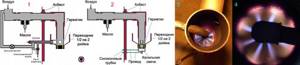
The pressure and amount of air supplied for combustion is regulated by a homemade damper (it is made according to the throttle principle, like in a carburetor).
The flap is installed in the supply pipe upstream of the fuel injector as follows:
- A hole for the rotary axis is drilled strictly according to the diameter of the existing workpiece.
- A round plate is cut along the inner diameter of the pipe, which in the closed position can completely block the hole.
- A rotary axis is made in the shape of the letter “L” and a damper is mounted on it with small bolts.
- In front of the damper, a hole is drilled or a slot is cut in the supply pipe to remove “excess” air (in case there is a lot of it for the burner).
The principle of feeding waste into the burner itself
To supply oil, a diffuser is installed in the intake pipe immediately behind the damper. The diffuser is a chiseled ring insert that slightly narrows the flow area. Thanks to it, a vacuum is created and oil (or other liquid fuel) flows through the nozzle and mixes with air.
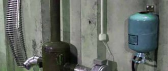
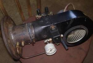
For the supply pipeline, it is preferable to use metal pipes. A freon tank is well suited for the fuel tank, and the needle valve allows you to precisely regulate the oil supply.
Simple homemade burner
The oil must be separated from water and filtered.
Principle of operation
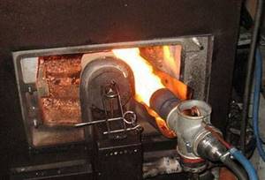
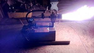
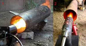
The fuel is supplied by gravity to the nozzle and is sucked in by air passing through the diffuser. The resulting mixture ignites inside the cylinder, and the torch is blown outside. Thus, the source of heat is the burner itself (heats up to a crimson glow) and the torch.
The flame can even be used to melt some metals such as copper, aluminum and others that have a lower melting point.
Operating principle of the burner during mining
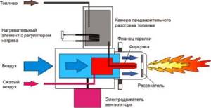
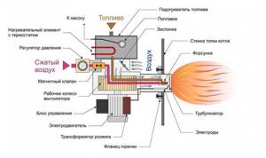
The design and principle of operation of the burner during mining is associated with forced heating and partial evaporation of the fuel. After fuel is supplied to the burner device, it is sent to the preliminary preparation chamber, where it is heated to the required temperature and oxidized.
The combustion of the air-fuel mixture occurs in a flame torch. Electrodes located directly in front of the spray nozzle are responsible for igniting the air-fuel mixture.
To maintain combustion intensity, air flow turbulence created by fan blades is used. The operating principle of the burner is identical to devices operating on diesel fuel or liquefied gas.
There is a certain classification of burner devices according to the type of power control. The consumer is offered the following types of burners:
- Single-stage burners have a simple design and operating principle. Heating of the coolant is carried out in 100% power mode. When the required temperature is reached, the burner simply turns off until the coolant cools down to the set values. After this, combustion resumes. The operating principle used in a single-stage burner device is ineffective and leads to significant waste of fuel.
Two-stage burners are modules that operate continuously without shutting down. The heating principle is as follows. The burner operates at 100% until the coolant reaches the required temperature. After this, it switches to a reduced power of 30 or 40%. The burner does not turn off completely. Smooth two-stage and modulating burner blocks have a similar operating principle.
The cost of two-stage and modulation burners is quite high, but the costs are fully recouped due to savings on fuel combustion, reaching 15-20% compared to single-stage analogues.
Preparing waste for combustion in a boiler
By itself, oil burns poorly; when burned under normal conditions, it releases a large percentage of soot and soot. The waste contains debris and metal inclusions. To normalize operation, the burner has two important components:
- Filtration system – used oils are purified before combustion. The filter is installed on the fuel supply line and before supply to the injector. The filtration system is ineffective if highly contaminated viscous oil is burned. Filters quickly become clogged, which leads to the boiler stopping.
Preheating chamber – the waste must be heated before being supplied to the nozzle. Oil brought to a certain temperature is more easily ignited and burns with a minimal non-combustible residue in the form of soot.
Organization of oil supply to the burner
Automatic waste oil burners use the principle of forced fuel supply. This device is more effective than the drip method used in homemade boilers.
In automatic burners, a pump is responsible for supplying fuel. Pressure is created in the fuel line, under which the heated waste material is supplied to the nozzle and sprayed. At the same time, a fan operates, creating a turbulence of air flows with its blades. Fine dust injected into the combustion chamber twists into a spiral and ignites, forming a flame torch.
Excess oil is returned to the fuel storage tank. The coherence of the operation of all components is ensured by the boiler automation, which simultaneously controls the pump, nozzle, and recirculation system.
Fire ignition and maintenance system
It has been experimentally proven that the optimal combustion temperature of a used oil flame is approximately 180°C. At this combustion intensity, the waste material burns completely, with virtually no smoke residues or soot.
The boiler contains several systems to ensure that the combustion temperature reaches the specified parameters:
- The pre-treatment unit is in the chamber, the engine oil is heated to 80-90°C.
Turbine - combustion intensity is achieved by constantly pumping air into the combustion chamber.
Ignition – electrical ignition is carried out. Immediately behind the nozzle, there are two electrodes that ignite the air-fuel mixture automatically.
Increased soot formation indicates a malfunction of one of the units of the ignition or fire maintenance system.
Drilling holes
In order for the air flow to atomize the fuel as efficiently as possible, the hole should be as small in diameter as possible. The priority is 0.010 inches. Although holes up to 0.020 in size are also considered acceptable. To obtain them, special thin drills are used. If you look at them from the side, they will seem intermittent. In any case, the drilling process should be done slowly and carefully. Compressed air will flow through these holes.
As for spraying using air, this option is more preferable than gas. This is due to the low cost of the resource. While you have to pay for gas, you don’t have to pay for air. In addition, you need very little of it, so you can use ordinary compressors, such as those used on aquariums. In principle, the Babington burner, the drawings of which you can find in this article, is almost ready for use. There are a few small parts left.
Do it yourself
The process of making a Babington burner is not very complicated and, if you have all the necessary materials and tools, it will only take a few days, depending on the skills of the person.
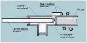
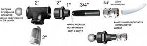
To manufacture this unit you will need the following materials:
- steel tube DN10,
- metal tee with a diameter of 50 millimeters with internal thread;
- a metal sphere (or hemisphere) with a diameter of less than 50 millimeters;
- copper tube DN10 at least one meter long;
- metal elbow DN10 with external thread;
- a bend with a diameter of 50 millimeters with an external thread, a length of at least 10 centimeters;
You will also need a minimum set of tools:
- angle grinder (grinder) or hacksaw for metal;
- perforator;
- special chuck for thin drills;
- drill;
- drill with a diameter of 0.1–0.3 millimeters;
- soldering iron;
Preparatory stage
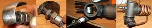
Before starting assembly, you need to make a hole in the sphere (hemisphere). This is one of the most difficult and critical stages, since the hole must be made exactly in the middle. Otherwise, the burner torch will be directed to the side, which in turn can negatively affect the quality of the product and its efficiency.
In addition, drilling holes of this diameter is a difficult task, since thin drills can break. Therefore, this process must be carried out carefully and slowly.
Step-by-step instruction
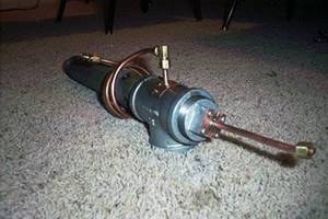
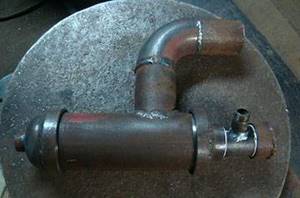
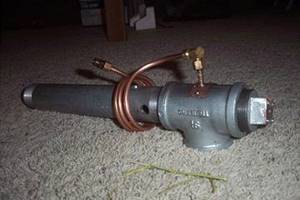
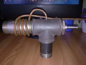
Once the sphere or hemisphere is ready, you can begin assembly. It is very simple and consists of several simple manipulations:
- The metal squeegee will act as a nozzle. It is cut to the required length and screwed into the tee. After this, a hole is drilled in the side of the burner, large enough so that the jet can be ignited through it.
- On top of the tee, closer to the nozzle, a hole is made for a copper tube through which fuel will be supplied to the device.
- An elbow is attached to the copper tube to connect the fuel line.
- A copper tube makes several turns (2-3 will be enough) around the nozzle. They must be done at some distance from the drive. This will allow the oil to be heated to the desired temperature before it hits the sphere.
- In the sphere, at the opposite end of the small hole, another hole is drilled along the outer diameter of the steel tube. The tube is hermetically inserted into the sphere. This is necessary so that the air exits only through a small hole, and pressure is created inside it. If a hemisphere is used instead of a sphere, then the tube is soldered at the small hole and sealed.
- From the opposite end from the nozzle, a metal tube with a sphere is inserted into the tee. She is fixed in it.
- Thus, the burner is ready for use. All that remains is to connect a compressor to the tube with the sphere, which will pump air into it and a fuel line to the copper tube.
- If desired, this system can be improved by connecting a pump to supply oil. You can also install a control unit with control sensors. This will make this system automatic and more secure.
Step by step guide
Step one is to drill a hole in the sphere. This cannot be done using conventional tools, because the hole diameter should be from 0.1 to 0.3 mm. You need a special drill and a special chuck. If you have a drill with a diameter of 0.1 mm, but the power of such a torch is not enough, you can make two or three holes. Such holes are drilled at high speeds.
When the sphere has a hole, it is attached to the air supply tube. Then the structure is installed inside the tee. A rubber plug is placed at the outlet of the tube from the housing, which is necessary to prevent air under pressure from escaping out. A hole is drilled in the plug through which the tube will pass.
Fuel supply
Amateur craftsmen often supply drip furnaces with single-stage fuel: an oil tank, a ball valve, and a supply tube. Firstly, this is dangerous: for convenience and safety of starting the stove, the valve must be placed closer to it. The supply tube gets quite hot when fuel is supplied from the bottom. If the heating passes through the pipe past the valve, up to which there is a solid column of fuel in the pipe, this could lead to disaster. Secondly, the fuel supply to the furnace is unstable: as the tube warms up, the drops become more frequent, because the oil thins out. If it flows in a trickle, then it is again dangerous.
The drip supply of oil to the furnace during processing should be organized according to a 2-stage scheme: main (storage) oil tank - valve - supply dropper - supply tank (tank) - free flow from it at least 60 mm from the bottom (for additional sedimentation of sludge) - working dropper. The fuel supply is opened when the kindling in the bowl (see below) is lit. While the oil drips into the tank to the level of the drain, you can slowly adjust its flow, and then it drips into the bowl drop by drop.
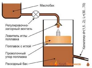
Scheme of safe power supply of a drip furnace from a supply tank with a safety valve and capillary
This system, however, is not completely safe. If in a hurry, out of ignorance, or simply trying to quickly warm up from the cold, open the valve too much, the consumables will immediately fill, fuel will rush into the stove, and it will throw out a tongue of fire and start spitting burning spray. It would be correct to build a drip oil supply system into the furnace with a safety float valve and a metering capillary (see figure on the right).
Since different metals are wetted by waste in different ways, and its properties vary significantly from batch to batch, the length of the capillary will need to be selected: the oil is fed under a gravitational pressure of 120-150 mm (from a suspended container) at room temperature, and the capillary is selected so that it drips more often, but with drops clearly visible to the eye. A diesel fuel drip furnace can be used from the same feeder, but the capillary will need to be taken with a clearance of 0.6-1 mm and a length 2.5-3 times longer than for mining. There is only one drawback to this scheme for supplying fuel to a drip furnace: the exhaust is dirty fuel, and the capillary will have to be cleaned periodically.
Nozzle
First you need to make a spherical nozzle; fuel will flow through it in the future. Make a hole in the sphere, the diameter should be approximately 0.25 mm
Please note that the power of a homemade burner depends on the diameter. The smaller the diameter, the lower the power and vice versa
All difficulties await you in the manufacture of the nozzle. The channel for air passage must be made perfectly smooth. It is necessary that the air hits forward and not against the walls of the nozzle. The best option is to make a hole on a special machine.
But if luck smiles on you and you find a jet with the desired diameter, then do not miss the opportunity and place it in the center of the spherical element. If you can’t find a hemisphere, you can use a small piece of sheet metal with a jet attached inside. As a result, you will receive an oil spray nozzle. Heated fuel will flow into it, and atomization occurs due to the incoming air. When installing such a device in a universal boiler, you get an effective and cheap heat source.
Equipment restructuring
It is much easier to build a burner from scratch than to do any modifications that require investment. For example, customer reviews indicate that rebuilding a diesel burner for maintenance costs fantastic amounts. The design is complex, requiring fuel heating. It is easier to order a ready-made spray device from China or purchase a domestic product, and the best option is to make the burner yourself.
A blowtorch burner is also not the best option. You need to remember how the soldering lamp does not stop working. Gasoline is poured into it, which is supplied to the atomizer under displacing air pressure. The spray device itself is preheated, since the fuel must burn in an evaporated state. Since gasoline is considered a highly purified fuel, it easily flows through the spray device without clogging it with impurities.
The use of a burner during mining is associated with the constant risk of fire, so having a fire extinguisher in the boiler room is strictly a priority!
In the case of used oil, everything is much more problematic - it contains very small particles of metal, gaseous, liquid and solid substances of gasoline, gasoline itself, various fractions of decomposed oil and other contaminants. The spray device in the blowtorch will become dirty very, very quickly. There are certain ways to update the spray device, but they are not justified. Thanks to this, we will further consider how to make a Babington burner with your own hands and save yourself from difficulties and high expenses.
Advantages and disadvantages of a liquid fuel burner
This equipment has a lot of advantages, the main ones are:
- Easy to make with your own hands and use.
- Wide distribution of drawings for the manufacture of fixtures.
- Cheapness of used oil used as fuel. These devices are perfect for transport organizations and companies where there is a lot of waste. In this way, waste can be disposed of and space heating can be carried out.
- Efficiency and functionality of devices.
- Mobility of the device.
Despite the listed advantages, the burner also has a drawback. It is quite demanding on the quality of used oil.
Complete photo and video instructions for making a burner using a blowtorch
Furnaces and boilers that operate during mining have long taken a good place among devices for heating premises. Mining is an inexpensive and sometimes free type of fuel; it is sometimes used for this purpose in car repair shops and garages. Many specialists, when choosing a design, ask themselves: is it possible to convert a gasoline lamp for soldering into a burner during testing?
Principle of operation
In most known oil burners, the oil-air mixture is supplied through a nozzle under pressure. In contrast, in the Babington system, oil is supplied by a low-pressure pump and flows freely over a surface shaped like a sphere or close to it. The fuel forms a thin film and evaporates, carried away by a stream of air supplied under pressure into a small (up to 0.3 millimeter) hole in the center of the sphere. Oil vapor and air mix, forming a torch of the fuel mixture. This torch is ignited and heats what needs to be heated - the walls of the furnace or the liquid heat exchanger of the boiler.
Operating principle
Some of the oil does not have time to evaporate and burn and flows below the hole, ending up in the fuel collection pan. The waste then flows from the sump into the fuel tank and is reused.
To increase the fluidity and volatility of the mining, it is heated. The heated waste is sprayed into droplets of a smaller volume, which also improves the quality of the fuel mixture and the overall efficiency of the device.
Finished equipment
HVAC and heating equipment stores sell burners using waste fuel (oil). An analogue of real stores are online portals for selling equipment. The list of available burners in terms of power and capabilities is extremely wide, as is the price range. The majority of the market is occupied by the following manufacturers:
- The stove is a “Gnome” class burner. Price niche from 40 thousand rubles. up to 450 thousand. Power range 35 - 1000 kW. Comparable to Amalthea burners.
- NORTEC is the most popular Chinese manufacturer. Budget options for 60 kW cost 75 thousand rubles. There are universal models of 1500 kW and costing more than 570 thousand rubles.
- Euronord is another Chinese company, the range of burners is 40 - 236 kW, priced at 90 - 150 thousand rubles. respectively.
- The domestic company Olympia has the highest price, up to 780 thousand rubles. for 500 kW, but the manufacturer has a RosTest certificate.
For the most part, store burners are ejection devices equipped with automatic systems, fuel heating and safety sensors. All control is carried out from an electronic remote control. There is also equipment for attachment to a boiler or heater. As you can see, even the most budget options have a decent price.
Starting the furnace
It has already been said implicitly that you need to start the drip furnace slowly and smoothly. Usually, for this they use a torch made from a knitting needle with a piece of foam rubber or a rag: let some drops in and place the torch. When it gets wet, they wait until a puddle drips into the bowl, light a torch, and pour oil into it.
There is a much more convenient and safer way to start a drip stove: a wad of toilet paper soaked in the same oil. They put it in a bowl, set it on fire and slowly regulate the drips, no longer worrying about kindling. Toilet paper is almost pure cellulose; it burns without leaving a residue. Tourists have been warming themselves in tents this way for a long time: the roll is inserted into a wood chip stove, poured with half a glass of alcohol (which also burns without a trace), or the whole thing, darling, and set on fire from above. A lot of heat is generated, and an insignificant amount of fluffy ash can simply be blown out. In the oven it will fly out into the chimney.
Additional Tips
When using a homemade burner, there are usually increased requirements for compliance with fire safety rules
Important to remember:
- Do not leave a working nozzle unattended.
- It is prohibited to install the equipment in a residential area.
- To heat the heating main boiler, a special room is usually made without flammable coating on the walls, ceiling and floor.
- To increase operating efficiency, heavily contaminated waste is enriched with clean oil.
- Reliable ventilation is built in the boiler room to remove gases and smoke after fuel combustion.
- Carry out regular maintenance and equipment reliability checks.
If used correctly, a homemade burner will last for many years. The savings from using this type of heating are obvious, because the used oil has already been paid for, and if not for the homemade firebox, it would have to be disposed of.
Final stage
Homemade exhaust burners bring joy to consumers with a powerful flame. However, to ensure their operation without interruption, you should carefully consider the design of external components. In our burner, waste oil flows through a spherical sprayer, but is not completely directed to the nozzle - a significant part is sent to the drain tank. From here it flows into the key tank, where there is a low-power tubular-type heating element. If you do not want to transfer fuel manually, use any suitable oil pump.
The pump itself is placed between 2 tanks - it sucks waste oil from the drain tank and directs it to the key tank. As a result, we acquire a fuel cycle. Customers can only top it up occasionally, since some of it gradually burns at the outlet of the spray device.
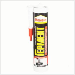
In order for the assembled device to last longer, all connections must be lubricated with high-temperature sealant.
As for the tubular heater, it should be equipped with a thermostatic valve. It is necessary for the first preparation of fuel. Used oil is quite viscous, and for the spray device to work, it must be more liquid. Due to this, it needs to be warmed up. However, not to a temperature of +250-300 degrees, as is done in evaporative burners, but only to +70 degrees. In this state, it is quite liquid enough to fall off in the form of very small drops from the surface of the spherical sprinkler.
As a result, we ended up with three energy-consuming nodes:
- Air blower - used to create a fuel-air mixture;
- Tubular-type heating element - converts used oil into a liquid state;
- Oil pump - drives unused waste oil from one tank to another.
We will not be able to make the burner non-volatile, since it is impossible to free ourselves from the air blower or the tubular heater.
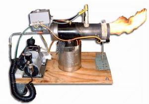
DIY Babington burner
A worthy alternative to store-bought burners would be to make your own waste oil burner. First you need to decide on the type of device. Ejection circuits are difficult for home production, and evaporation circuits have a limited scope of application. This means that the best option would be the Babington device, which was originally intended to run on diesel fuel.
The key operating principle of this burner is that a stream of compressed air is supplied directly through the waste layer. Also, the device does not have bottlenecks that could become clogged with dirt. To create burner units you will need the following materials:
- The fuel unit is a tank with a heating element with a power of up to 1 kW made of stainless metal. A sump with a pipe, a drain with an inch thread and a 2/1-inch adapter for draining excess waste oil into the tank. Copper tube with a diameter of 1 cm and a thickness of up to 0.15 cm. An oil pump with an electric motor, equipped with an oil filter with a large mesh (can be removed from a car or motorcycle).
- Pneumatic unit - a compressor with a permissible pressure of 2-4 atm., a tube for an air stream with a diameter of 1-1.5 cm.
- The fuel-air mixing chamber is an empty metal ball or hemisphere with sufficient thickness for a 0.3 mm hole (nut with a plug, brass door handle, etc.).
- A nozzle that directs the flame in the desired direction. Length 20-40 cm, external thread with a diameter of 2 inches.
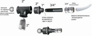
- Connecting parts (fittings) and transition parts (adapters) allowing you to assemble the entire unit into a single burner.
Preparing burner modules for assembly
The role of the key part is given to the hemisphere in which the used oil is mixed with oxygen. You need to drill a hole in it, which affects the power of the future burner. For a 15 kW heating boiler, a nozzle with a single hole of 0.2 mm is suitable. Greater burner power can be achieved with 3-4 holes of 0.1-0.25 mm, with a mandatory distance of 0.8-1 cm (so the torches from each hole will not extinguish each other). One quarter-centimeter hole consumes 2 liters of waste oil per hour of operation.
The fuel tank is made of corrosion-resistant metal, as is the fuel sump. The latter is equipped with a tube through which waste oil flows back into the tank. A plug is made at the bottom of the sump to drain the dirty residue. A heating element equipped with a regulator is built into the tank, which will turn it off at 70°C.
The role of the body is played by a cross or tee, to which the nozzle and adapters are mounted. At the top there is an oil supply, at the rear there is a compressed air supply, at the bottom there is an adapter for draining excess fuel. The role of adapters is played by plugs with holes for air and oil supply pipes.
The pump motor for supplying waste is connected to a network with a voltage of 220V. Oil (waste) from the tank flows through a copper tube, on the one hand, wound three times around the nozzle, and on the other, led into the tank through an oil filter.
The air tube is attached to a hemisphere with a drilled nozzle and a plug adapter is installed. The hemisphere itself is positioned in such a way that the fuel from the copper fuel tube completely covers the nozzle, and the remainder flows into the sump. The duct compressor is also connected to the household network.
Preparing fuel for the burner
A device operating on waste oil consumes any type of waste. Motor oils with high water content are mixed with diesel fuel (or clean oil) before filling. Mining with moderate contamination can be poured immediately.

It is advisable to let edible oils stand before use, then drain the remainder. Fuel oil and viscous fuels and lubricants need to be heated to 70-80°C. For greater efficiency, 10% diesel fuel is added to synthetic and mineral oils when filling.
Safety precautions
- There must be fire extinguishers in the room where the device is used.
- If the floor and walls of the room are made of flammable material, they are sheathed with asbestos or metal.
- Fuel is stored at a distance insufficient for ignition from burner operation.
- Oily stains are removed in a timely manner.
- A working burner must not be left unattended.
The Babington burner is a reliable device with an extended service life and is designed to bring savings to the owner.
Do-it-yourself burner: operating principle
If you look at photos, pictures and drawings, it becomes obvious that the secondary oil forms a thin film on a curved surface. Through a groove, gas or air is supplied into the container under low pressure. After heating, the oil is atomized by this air flow, ensuring high-quality ignition.
It was this method of ignition that became the basis for inventions that have become widespread in homemade devices and drip burners using waste oil, produced in factories. Used oil is essentially free fuel, a used suspension. Therefore, it is considered more advantageous compared to other heat sources:
You can make a waste oil burner yourself
- solid fuel and briquettes for a homemade pellet burner;
- gasoline and diesel fuel;
- electricity;
- natural gas;
- kerosene;
- fuel oil.
The first devices using kerosene, diesel fuel and oil smoked heavily and emitted an unpleasant odor. Later they offered a do-it-yourself gasoline burner and devices using other combustible raw materials, but an active search was underway for budget fuel. Oil turned out to be a suitable source of heat, but the soot and smell negated all the benefits. Therefore, all the efforts of the inventors went into eliminating these disadvantages of the burner for waste oil boilers. This should have been facilitated by complete combustion, heating and filtration of contaminated fuel.
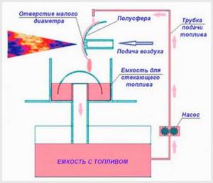
How to build your own apparatus based on the Babington burner principle: drawings
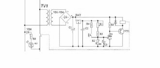
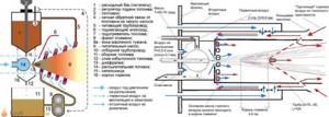
The principle of operation of a homemade burner, made based on the idea of Robert Babington, is clear from the drawings, where the components of the unit are visible:
Drawing of a waste oil burner according to Babington
- waste oil tank;
- waste tray;
- fuel supply pipe;
- a small fuel pump for supplying portions of oil;
- hemisphere for spraying with a small hole;
- heating chamber with heating element (may be missing).
The used oil evaporates and flows down the hemisphere. These oily vapors are mixed with the air mass, resulting in a fuel mixture. The remaining oil that has not had time to be utilized flows into the pan, and from there through the tube back into the fuel tank.
This unit, based on Babington's patent, designed to burn liquid fuel, is quite simple. Therefore, it can be reproduced from scrap parts in a home workshop. Success depends on the exact compliance of the parts with their intended purpose and on the coordinated operation of all components. Therefore, before making a burner with your own hands, you should carefully calculate all the parameters.
The design of the burner is quite simple, so it can be made from available materials
Design Features
The design is based on a hemisphere (ball) through which fuel flows in a wide stream from top to bottom. The hemisphere has a very narrow hole through which an air stream is supplied. The air sprays oil along its path, forming a stream of finely dispersed mixture, which is ignited and burns safely.
Air is supplied to the hemisphere under low pressure (up to 0.5 atm) by a compressor, and oil drains from a pressure equalizer tube (same level with overflow). But the viscosity of the oil should not be high and stabilized. To do this, it is heated in a copper tube, which wraps around the burner in 2–3 turns, which stabilizes the thickness of the flow on the hemisphere, and hence the combustion power.
Productivity (power) is actually determined by the area of the hole in the hemisphere and the thickness of the oil flow (its viscosity), i.e. the volume of oil that the air stream will spray per unit time. Unatomized oil flows back into the tank with a pump or into a sump, depending on the design.
And another important point that is sometimes forgotten: holes are made in the burner nozzle (preferably adjustable), through which secondary air is drawn in, with which complete combustion occurs.
This is interesting: Do-it-yourself water heating of a private house, design diagrams
Burner features
In order to burn the oil effectively, it will need to be heated first and then sprayed. For this purpose, an electric heating element is installed. But the energy consumption will be quite large. And the main thing for you in manufacturing is to achieve minimal losses when using the device. The burner must be a source of very cheap heat, which cannot be realized when using heating elements.
If you can’t warm up the oil first, you need to try to atomize it. The simplest burners made according to the Babington scheme can be successfully used in boilers. The design is extremely simple - fuel flows over a spherical surface. A thin hole is made in the latter; compressed air is supplied through it. It turns out that the oil is blown away from the sphere, small drops are formed, which can be ignited.
Operating principle of the burner
The burner works by atomizing fuel with a stream of high-pressure air. The fuel flows down a spherical surface in which a small hole is drilled. Inside the sphere there is a tube through which air flows under pressure. It bursts through a narrow hole, tears off part of the fuel and sprays it, forming a conical torch.
The rest of the fuel flows by gravity into a special settling tank, which is located under the sphere. It can then return to the main reservoir.
Some consider the principle of operation of a torch to be similar to the principle of operation of a blowtorch, but there is a significant difference between them.
Operating principle of the burner during mining
In a blowtorch, air displaces the fuel, but does not mix with it. And in a Babington burner, a stream of air passes directly through the fuel stream, forming a cone of atomizing aerosol. This ensures better contact of small droplets with oxygen in the air and allows the fuel to burn more efficiently. That is why it became possible to burn oils, while a blowtorch uses gasoline.
Kinds
These devices may differ from one another in several ways. First of all, if possible, regulate the power. There are three varieties:
Single stage

These are the simplest burners, the thermal output of which, also known as power, is always constant.
The amount of incoming heat is regulated by periodically turning on/off the burner.
The advantage of this device is its low cost.
The disadvantage is that all elements of the boiler, and especially the heat exchanger, operate with maximum thermal load and under conditions of sudden temperature changes. And this negatively affects the durability of the heat generator.
Two-stage
Such devices can operate in two modes: with maximum performance and half. Half mode is used as an intermediate mode for smoothly reaching maximum power, or as the main mode in relatively warm weather.
A two-stage burner is more expensive than a single-stage burner, but the boiler equipped with it operates in a gentle mode, and therefore lasts longer.
Modulated
The most expensive type of diesel burner, which is characterized by the ability to smoothly regulate power over a wide range - from 10% to maximum. Such burners do not turn off, but operate constantly - with the productivity that is required at the moment. This not only reduces the thermal load on the heat exchanger and furnace, but also eliminates temperature changes.
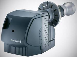
Diesel burner M 302
In addition, fuel consumption is reduced. After all, the operating scheme of one- and two-stage burners assumes some overheating of the coolant, as a result of which the amount of heat loss increases (it is proportional to the difference in temperature inside the room and outside).
If the boiler is equipped with a modulating burner, no overheating occurs (the temperature is maintained at the set point all the time), so heat loss, and therefore fuel consumption, becomes minimal.
Other types
Diesel burners also differ in the method of supplying primary air, which is used to prepare the fuel-air mixture. On this basis they are divided into two types:
- Diffusion (atmospheric): the simplest burners in which air is sucked in due to the pressure drop in a moving liquid stream. But with this method it is not always possible to ensure the supply of a sufficient amount of oxygen, so the fuel may not burn completely. The consequences are a drop in the efficiency of the installation and the formation of a large amount of soot.
- Pressurized or blown burners: Equipped with a fan that provides forced air supply in any volume. They cost a little more, but the fuel burns completely under any conditions.
Particularly powerful heat generators are equipped only with forced-air burners.
What is a Babington burner?
A homemade oil burner can be used for various purposes, for example, to work with a combination boiler or as part of a simple liquid fuel stove. The main task is to assemble a spray device that will produce a powerful flame. Here are the requirements:
- Minimum electrical energy consumption;
- Ease of manufacture;
- Greater efficiency;
- Excellent homemade performance even on contaminated fuel.
We have already told you that in order to burn waste oil well, you need to heat it or spray it. It will not be difficult to heat it up to a high temperature using a tubular heater, but this is dangerous due to excessive costs of electrical energy. A liquid burner must become a source of inexpensive heat, but in the case of electric heating (evaporation), this is unrealistic - tariffs for housing and communal services in our country are quite high.
Since we cannot ensure the heating of the used oil with its further evaporation, therefore, it is necessary to try to spray it. Actually, this is what makes it possible to do this with the Babington burner, which has an extremely simple design. If we take the simplest drawing, we will see that fuel here flows along a spherical surface in which a thin hole is made - air is supplied through it, coming out of the air blower. A jet of air blows away particles of used oil from the surface of the sphere, resulting in the formation of a fuel-air mixture.
The above diagram gives, albeit somewhat simplified, but still quite intelligible explanation of the working principle of the burner.
The resulting mixture is ignited, and the burner flame is used for one purpose or another. For example, nothing prevents you from installing a burner in a combination boiler, which will work with a wide variety of fuels. It is also possible to make boilers yourself; there is nothing complicated about it. An interesting point is that there is practically no disappearance here - the process actually occurs at a low temperature, due to the pressure of air from a very thin hole.
The Babington burner is a very simple device, but to make it you will still need some skills, which, apart from experimental methods, are unlikely to be obtained anywhere.
The Babington burner has many positive qualities. First of all, it does not require pre-purification of used oil, and there are very, very many impurities in it - it’s not for nothing that it has such a black color. Secondly, it is not difficult to manufacture. If you love and can work with tools, you can easily assemble it and have a simple and effective heat source at your disposal.
The evaporative burner during exhaust requires another heat source. This leads to the need to use a significant amount of electrical energy or to a more complicated design - it is necessary to somehow heat the fuel so that it begins to disintegrate into flammable fractions. Babington's circuit is much simpler - it is difficult to do without an air blower, but it can do without evaporation. It takes into account the simplest spraying of fuel, after which it lights up without much difficulty.
Manufacturing recommendations
There are several useful recommendations that will help in making a burner:
- The hole should be exactly in the center of the sphere, and its axis should coincide with the axis of the air duct. Otherwise, the torch will hit to the side, and this creates additional danger.
- Instead of drilling a hole, you can use a ready-made jet. To do this, a hole slightly smaller than the outer diameter of the nozzle is drilled with a conventional drill, then it is modified manually, and the nozzle is simply hammered inside.
- If there is more than one hole, the distance between them should not be less than 7 mm.
- To ignite, you need to make a hole in the side of the nozzle.
- In the simplest case, fuel should be supplied to the burner by gravity, but a fuel pump can also be used.
- Even a low-power compressor (for example, from a refrigerator) can cope with air injection. The working pressure inside the sphere does not exceed 4 Bar (4 * 105 Pa).
It is not necessary to use a heating element in the design. When starting the burner, you can use a propane torch, hot water, or even an old coffee maker to preheat the oil.
How to make a burner yourself
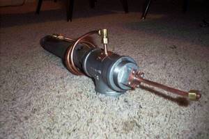
The simplicity of the burner design allows it to be easily manufactured in a home workshop or garage. Let's look at how to make a burner of the simplest design.
First of all, you should select materials:
- The body of the future burner is a steel tee with internal thread. Inner diameter – 50 mm.
- The nozzle is made from a squeegee (a piece of threaded pipe). The outer diameter must be 50mm to fit the body. The nozzle length is not less than 100 mm.
- Connection to the fuel line is made through elbow DN 10.
- The fuel line is a copper pipe DN 10, at least a meter long.
- The air duct is a steel tube of the same diameter.
- A metal sphere or hemisphere that can fit freely into a tee.
- Fuel tank and settling tank.
- Heating element for fuel.
The fuel tank should not be located in close proximity to the flare. Otherwise, a fire will occur.
How the burner came to be
Back in 1969, inventor Robert Babington was awarded a patent for this burner. True, today its term has long expired. In 1979, Babington proposed a new burner design. It was fundamentally different in that it had a double air spray. This invention was very similar to the Airtonic burner, which was also made using the technology of this inventor. It was used for military purposes in a field kitchen. Naturally, the burner was powered by diesel fuel and was irreplaceable. The final version was proposed by John Archibald. Many people call this man the inventor of the Babington burner. But it is impossible to give a definite answer. And it is unlikely that this plays a significant role for us. The most important thing is to be able to create such a unit with your own hands and ensure its efficient operation. Fortunately, doing this is not as difficult as it might seem at first glance.
Security measures
- A burner using oils and other GSPs can be dangerous if installed and operated incorrectly. To avoid a fire, a number of measures must be observed:
floors and walls made of flammable materials are sheathed with metal or asbestos sheets; fuel reserves are stored at a safe distance; oil leaks must be removed in a timely manner; electrical elements of the installation must be carefully insulated to avoid sparking in the oil spray area; The burner must be placed out of reach of air currents and drafts.
A burner with an open nozzle must not be left running unattended!
The Babington burner, unlike a blowtorch converted for working in mining, is a reliable and durable unit that does not require complex maintenance. It is enough to periodically clean the fuel system, tank and sump, blow out the air duct in idle mode, and also monitor the serviceability of the compressor and oil pump. A working burner is a reliable and economical unit with a long service life.
The idea of using used machine oil as burner fuel is not new. There are many different schemes for making such a device on the Internet. And the popularity of such products is only growing. This is understandable, because such a device will be very useful in everyday life, heating a country house or utility room.
In addition, it has a number of advantages:
- Most of the proposed schemes are simple, and anyone with a minimum of necessary skills and tools can assemble it.
- The fuel for this burner is very affordable. It can mainly be found in auto repair shops, where there is simply an overabundance of it. Thus, used oil can be obtained for free or for a minimal amount.
- The question of recycling used oil often arises, and such a burner will help dispose of it without harming the environment.
- This device is multifunctional and can be used as a regular burner or an oil heating system.
- Such a device, as a rule, is mobile, as it is light in weight and size.
- This burner is universal in the type of fuel used. In fact, it can operate on any combustible fuel, be it used engine oil, gasoline, kerosene or any other.
Among the many schemes, one is the most interesting in terms of simplicity, functionality and unpretentiousness. This miracle unit is called a Babington burner. It is named after its creator and its device was unavailable for a long time due to a patent. But the patent has expired and now anyone can bring the scheme to life.
The principle of its operation is very simple and includes the following stages and parts:
- Preheated fuel falls on the sphere, spreading over it evenly, forming a thin film.
- A compressor is connected to the sphere itself, pumping air. A very small hole is made in the sphere, with a diameter of 0.1-0.3 mm. Air under pressure exits the sphere through this hole. Passing through the fuel, the air disperses it, forming something like an aerosol.
- Next, this jet is ignited and a burning torch is obtained.
- The rest of the unused waste flows into the settling tank and can be reused.
- In order for unused waste oil to be automatically supplied to the sphere again, it is necessary to connect a pump to the system, which will supply fuel from the sump.
Preheating the fuel solves 2 problems at once:
- Increased fluidity. The heated waste oil spreads better over the surface of the sphere and is atomized much more easily by the supplied air.
- Facilitates the process of igniting the torch. At the same time, it is not only easier to launch the device, so to speak, but the efficiency also increases.
The advantages of this scheme include:
- Versatility in fuel use. Such a burner is practically independent of the degree of contamination of the liquid energy carrier.
- No filtering required. Due to the fact that there are no narrow passages in the system, except for the air hole, it does not require filtration, unlike factory analogues.
Schemes and designs
Ejection
Another feature of mining as a fuel is that it is very difficult to supply all the air necessary for its combustion under pressurization; a lot of it is required. Therefore, by pressurizing in burners of this type, fuel is mainly drawn out from the ejector nozzle and atomized, and air for afterburning is sucked directly into the flame. This scheme makes it possible to use electric power of up to 100 W for supercharging, and the rest is spent on heating the fuel with a heating element. In general, the idea is this: we use part of the electrical power (with a significant increase, by the way) necessary for pressurization with more fluid fuel to heat the waste, and a generally conventional ejection burner works on it.
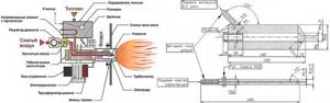
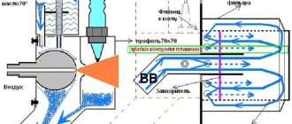
Diagram of the ejection burner during testing and drawings of the nozzle for it
A well-known diagram of the design of an ejection burner during testing and drawings of its heart - the nozzle for approx. 3-30 kW are given in Fig. Such a burner is installed on a blind flange in the combustion opening of the furnace/boiler, and secondary air is sucked into the torch through the ash pan. However, in addition to the nozzle, there are still subtle points in this design.
Turbulizer
The first of them is an air flow turbulator (swirler in the diagram in the figure above). Pressurization of the ejector burner during processing can be provided by a built-in volute fan or, through a gearbox, by the pneumatic system of the enterprise or by an industrial (possibly domestic of a similar design) piston compressor. For a burner power of about 3-15 kW, boost from a refrigeration compressor of 250 W electric is also possible.
Depending on the method of pressurization, the design of the turbulator changes. The compressor or compressed air distribution for driving pneumatic tools provides, under the conditions necessary for fuel ejection in the burner air jacket, an air flow that is too powerful and fast. The same is possible with a snail that is too powerful, for example taken from old trash. In this case, the turbulator should be an annular diaphragm around the nozzle with wide, slightly curved outer blades, pos. 1 and 2 in Fig. A pseudo-laminar jet of air from the diaphragm will pull the fuel out of the nozzle and ensure its stable ignition (see below), and 3-5 cm from the diaphragm, the burning oil mist will be picked up by a powerful whirlwind, atomized until it evaporates and is completely burned.
Design of the turbulator (swirler) of an ejection burner during testing, depending on the pressurization method
If the air flow is optimal (built-in volute by calculation) or weak (compressor from a refrigerator), then a turbulator made of many narrow, more curved internal blades is combined with the diaphragm, and an annular gap of 0.5-1.5 cm is left along the edge of the turbulator. Diaphragm - the swirler has less resistance to the air flow, a weak but immediately well-twisted vortex effectively sucks out and sprays the fuel, and the annular flow from the gap prevents the vortex from spreading to the sides until the fuel evaporates in the torch.
Note: the appropriateness of one or another turbulator for a particular burner is determined by experience - fuel ignition should be stable, and there should be no flameouts throughout the entire burner power adjustment range. You need to start with the diaphragm with the outer blades, bending them more and more. If it doesn’t work out, you need to switch to a turbulator diaphragm with internal blades.
Ignition
The second subtlety is igniting the torch. An auto candle with a removed “foot” (body lamella) is not very suitable, because designed to ignite light fuel vapor with a short spark, and not heavy fog with a long spark.
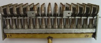
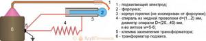
Method of igniting the fuel of an ejection burner during production using two electrodes
The burner torch must be ignited during production using electrodes for igniting liquid fuel boilers, see fig. The distance between the dischargers (spouts, points) of the electrodes is required to be 3-8 mm (for burners 3-30 kW), and the distance from the bare metal parts of the electrodes to the nearest metal parts of the structure must be at least three times greater. Turning on the nozzle: at the moment of ignition, the spark gaps must be in the oil mist emitted by the nozzle and ignite it with a spark among themselves. Ignition with a spark from a spark gap to the injector will produce a weak, unstable flame that can easily be disrupted by fluctuations in boost or fuel supply.
To ignite with two spark gaps, a special ignition transformer with an insulated secondary winding of 6-8 kV is required. Its terminals are connected to the ignition electrodes with wires in thick, from 2 mm, heat-resistant insulation made of silicone or Teflon (fluoroplastic). The latter is better: when heated to 150 degrees, the penetration resistance of fluoroplastic-4 remains approx. 80 kV per 1 mm, and silicone will not exceed 20 kV/mm. Such a huge margin of electrical strength is necessary due to severe contamination of the wires during operation.
A special ignition transformer is expensive because... These are produced for boilers from 20 kW. If the burner power is up to 15 kW (and for the Babington burner described below), you can use a single-wire ignition circuit from a car ignition coil with a spark from the electrode to the nozzle; This means the presence of only one high-voltage wire. The condition is manual switching to the mode: the burner is lit at minimum power and manually brought to the standard setting, making sure that the torch does not clog in convulsions or break.
To ignite the burner during testing using a single-wire circuit, the body terminal of the transformer is connected to the burner body and the nozzle with different return wires. The spark is not a direct current, but a pulsed discharge, and the electrical circuit becomes sensitive to the presence of reactivity in it. The electrical reactivity of the massive burner body is greater than that of the nozzle, which already makes it easier for the spark to choose the nozzle. If you additionally include a small inductance in the body return wire (see figure), then single-wire ignition will become quite stable.
Burner ignition circuit for testing with one electrode
About automation
Burners for testing, the operating mode of which is set from a remote control (for example, the well-known NORTEC) are very expensive, but without automation there is no point in installing a homemade ejection burner for testing: even with a fixed power and filling with fuel from the same batch, it is necessary to regulate simultaneously to obtain a stable flame fuel heating and air supply. Therefore, homemade ejection burners during development (excluding samples, just to tinker with them) are made semi-automatic with manual power setting and the use of relatively inexpensive automation from heating boilers, see for example. video
Video: burner in operation with automation
Babington burner
Robert Babington himself, who patented his burner in 1979, admitted that, having despaired of coming up with a nozzle that would not become clogged from working out, he remembered one of Murphy’s laws, which states: “If the iron still doesn’t want to work, try making it it's the other way around." Babington tried blowing air through a thin layer of oil - it worked. The fog began to set in, and how to burn it is a known matter.
This technical solution was possible due to the fact that oil is a rheological liquid. Simply - superfluid. It is not only exotic helium II that is superfluid. There are plenty of rheological fluids all around us. Anyone who has forgotten an open jar of sunflower oil on the table will immediately understand.
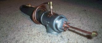
The design of the Babington burner and the combustion chamber (afterburner) for it
The design of the Babington burner is shown on the left in the figure, and on the right is the design of the combustion chamber (afterburner) for it. The disadvantage of this burner is already visible here: to burn the waste by more than 95%, a 3-stage air supply is required (except for atomization), and partially heated. Although boost is still not required.
The Babington burner operates quite simply: fuel drips onto a spray head with a spherical surface, which ensures its uniform spreading. It drips in excess so that the air always has something to blow off. The oil thrown out by a jet of air from the nozzle in the head forms a mist, which is set on fire. The fuel film constantly creeps onto the nozzle due to the rheological properties of the oil. Excess fuel flows into the collection tank, from where the feed pump supplies it through the heater back to the supply tank (feeder). Often, instead of a float turning on the pump, the feeder is provided with the excess in the tank draining directly into the collection tank; In this case, the feed pump operates continuously. However, the Babington burner also has enough design nuances.
Is a full sphere necessary?
The power removed from one Babington burner nozzle is limited by the finite value of oil fluidity. Therefore, the heads of powerful Babington burners are literally riddled with pores. If no more than 5-7 kW is required from the burner, it is possible to use part of the spherical surface instead of a technologically complex full-spherical head.
Design of a Babington burner with a head in the form of part of a sphere
The design of a Babington burner with a partially spherical spray head is shown in Fig. (how to make one is described in detail and with photos here: diyworkplace.ru/14-diy-oil-burner.html). In addition to the availability of materials, it is good to learn how to adjust the fuel supply with this burner: a little more, the oil flows behind the blade of the head, stinks, burns, and clogs the spray chamber.
The sphere is still better
The spherical head in the Babington burner is also better because it saves fuel: in a burner with a partially spherical head, a good portion of the return burns until it is impossible to use. In the end, it turns out that there is still a quarter or more in the tank, but the burner does not start.
How to make a Babington burner spray head from inexpensive materials for a completely different purpose, widely available, is shown in the figure:
How to make a Babington burner spray head from scrap materials
The good thing about a curtain rod plug is that its cut surface is flat and even. Drilling a nozzle hole in such a head blank is not difficult on a conventional drilling machine. If it moves away from the pole of the sphere within 1-2 mm, it’s okay. The main thing is that the axes of the nozzle and the sphere will be parallel and the torch will shoot evenly. You can even increase the power of the burner by drilling 3-4 holes around the pole of the sphere no closer than 6 mm from each other in a triangle or square. All that remains is to decide - how to drill?
How to make a 0.25 hole with a 0.6 drill
The permissible limits for the diameter of the Babington burner nozzle are 0.1-0.5 mm. Less maximum power is removed from a narrow nozzle, but the range of its adjustment is expanded, which is carried out by changing the air pressure for spraying. The latter for a 0.1 mm nozzle can vary within 0.5-5 atm, for a 0.25 mm nozzle - 1-3 atm, and the pressure in front of a 0.5 mm nozzle must be kept within 2 (+/-)0, 2 atm, otherwise the flame either breaks or goes out. Babington recognized the nozzle diameter of 0.25 mm as optimal; narrower nozzles become clogged with dust from the air, which requires at least 2-stage cleaning.
But how to drill a hole with a diameter of 0.25 mm? You can’t buy drills like this everywhere, and the machine needs high precision, otherwise the drill will immediately break.
The way out is to make a nozzle from part of a needle from a medical syringe. The channel diameters of syringe needles are 0.2-1 cubic meters. cm are just within optimal limits, and their outer diameter is 0.4-0.6 mm. These drills are widely available, and they can be inserted into a regular tabletop drill. Making a Babington burner nozzle from a medical needle is done as follows. way:
- Cut a piece from the needle 2-3 mm longer than the thickness of the head wall.
- We use a thin, stiff wire to remove sawdust and burrs.
- Using a drill slightly larger than the outer diameter of the needle, we drill a pioneer channel in the head. If you use a 0.6 drill to drill a channel for a 0.4 needle from the outside, it’s okay.
- Using a drill with a diameter 0.15-0.2 mm larger than the pioneer one, we countersink the hole on both sides. The chamfer needs to be removed tiny, so we countersink by hand, wrapping the drill shank with electrical tape and turning it with your fingers.
- We insert a piece of needle into the pioneer hole.
- Using two sharp awls or, better yet, metalworker's scribers, we unfold the ends of the needle segment. You need to unfold it at the same time, pressing lightly and turning the tools in opposite directions.
- We leave the bell inside as is, it does not interfere with anything.
- We remove the external excess using an emery stone no rougher than No. 360.
- Once again we clean the nozzle channel, blow it out - the head is ready.
What if the head is already ready?
A very possible option. If you take a ready-made diesel fuel nozzle onto the head; A defective one made from junk or cheap will do. Fans are confused by the fact that they are produced with a power of 20 kW, but in this case there is nothing to be afraid of, because It is not diesel fuel that will flow into the nozzle, but air. But its working surface is precisely hemispherical, mirror-smooth, with a collar that prevents the oil from flowing where it shouldn’t and burning. The nozzle, however, will be from 0.7 mm, but it can be narrowed as described above. How to make a Babington burner head from a diesel injector, suitable for long-term intensive use, and even with automation from a water heating boiler, see the story
Video: Babington burner with automation
Compressor for atomization
Atomizing air in a Babington burner requires a little air, but under decent pressure. A compressor from an old refrigerator is best suited for this purpose, but you need to put a car air filter in front of it, otherwise the vacuum pump will quickly fail. You also need a receiver, because... Such a compressor will produce a highly pulsating jet.
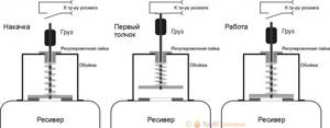
How to adapt a compressor from a refrigerator to supply air to a Babington burner during mining
The great advantage of such a system is the ability to automate burner ignition without electronics. For this we use a safety valve (see figure), because The refrigeration compressor builds up pressure to more than 5 atm. Let's take the worst valve, a disc valve with a flat seat (the disc and seat will need to be ground together with abrasive No. 600 or finer and washed with alcohol). Such valves have a large hysteresis (the ratio of opening and closing pressures), but in this case that’s what we need. We will also increase the hysteresis of the valve by placing a weight on its stem. When the compressor pumps the receiver to the initial response pressure, the valve will “puff” sharply, jump up and close the microswitch that supplies power to the ignition transformer for 1-2 seconds. The oil consumption will go up for combustion, the air flow will increase (it is more difficult to blow through a cold oil film), and the valve will begin to work part-time, not reaching the mic. The adjusting nut is convenient for changing the air pressure to change the burner power.
Compressor lubrication
In a refrigerator, the compressor is lubricated with refrigerant, because It pumps out freon mist from the evaporator rather than pure steam. Suddenly the compressor starts to sputter, which means that there is too much refrigerant and it circulates in the system in a droplet-liquid state. If you force a refrigeration compressor to pump air, it will soon deteriorate without lubrication.
You can lubricate the refrigerator compressor with a spindle or other machine oil for precision mechanics. First you need to make a lubricant dispenser, from a 50-100 ml tank, a needle from a regular syringe for 2-10 cc, a tube from a blood transfusion machine and a pair of clamps from the same. The upper one shuts off the lubricant supply, and the lower one regulates its amount.
The dispenser is adjusted in free space. It is necessary to ensure that a drop of lubricating oil accumulates on the tip of the needle, pointing straight down, for 2-4 minutes, and hangs for the same amount of time until it comes off. Then the needle is inserted perpendicularly into the compressor supply air duct so that its bevel is in the middle of the lumen and oriented along the flow. If the needle is turned sideways or against the air, the oil will not flow.
The system is ready for use, but you will still need to monitor it during operation. Suddenly, some time after starting the burner, the combustion character changes, which means that a lot of oil goes into the compressor and it drives the excess with air. If at least 10 minutes have passed before this, and the flame remains, just begins to pulsate or smoke, you can correct the matter by slightly turning the needle, no more than 45 degrees. If it doesn’t help or symptoms appear earlier, you need to reconfigure the lubricant dispenser for a longer drop accumulation time.
Flame down the chimney!
You can do an interesting experiment with a burner during testing, the results of which are visible in the trace. rice.:
Using a burner during mining to heat rooms
Having passed the burner flame through just 1 m of a wide pipe, we will see it no longer so furious and much cooled down (pos. 1), and a powerful flow of heated air will be noticeable from the pipe up. If you take a pipe with a diameter of 200 mm and a length of 3 m (item 2), then the temperature of the gases at its outlet will drop to less than 100 degrees. Let's expose the mouth of the pipe to the outside - the oily stench in the room will no longer be felt, although the gas analyzer will show that the impurities exceed the housing norm. All that remains is to hermetically connect the mouth of the pipe to the chimney, and we will get a heating system with an efficiency of more than 80%.
Evaporative
The waste can be burned without pressurization or heating at all, by dropping it drop by drop into a hot bowl. But such devices, as mentioned above, work more or less decently only as part of a boiler or furnace during mining, so they are not burners in the proper sense and are discussed in other publications.
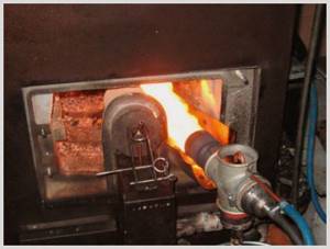
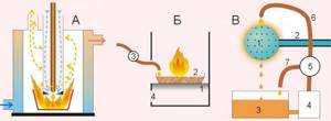
Evaporative fuel-air (cup) burners in production
A fuel-air mixture is supplied to the bowl of the evaporation burner during exhaustion, i.e. a small boost is required (fan from 20 W). The bowl is preheated either with a gas torch (item 1 in the figure), or with regular fuel supplied dropwise (not yet pressurized), ignited by a glow plug (item 2). The latter is easier, but during the first 3-5 minutes there will be a lot of soot. When the flame from the next drop is cleared and begins to rise with noise, the candle is turned off and air is allowed in. Blue tongues will appear in the bowl (positions 3 and 4), indicating complete combustion of the oil, but impurities in it will transform into a chemically more aggressive form and go into the air, so you need to use evaporation burners during processing carefully, see above. The evaporation burner is not critical to the size of the parts; base – 1/2″ and 2″ water pipes.
Note: for temporary start-up of, for example, a garage potbelly stove, it would be more convenient to use an evaporative burner that operates on the same principle, but into which the fuel-air mixture is supplied tangentially from the side, see the video below:
Video: evaporation burner in production for a furnace
Why work off
Drip fuel supply is widely used in heating engineering when a heat output of approx. up to 15 kW. The principle of operation of a drip furnace is simple: liquid fuel drips into a heated evaporator, into which primary air is supplied. Each drop evaporates and partially burns immediately, maintaining the temperature of the evaporator. The remaining fuel vapors enter the combustion chamber with the influx of secondary air, where they burn completely. Thus, in drip furnaces, 2-stage fuel combustion is carried out. Unlike stoves with non-pressure burners, where the fuel heats only itself until it evaporates, in drip stoves part of the heat from the combustion of each drop is spent on heating a rather massive evaporator, which determines their lower efficiency. But there are ways to minimize this disadvantage, see below.
The maximum power of a drip furnace is largely determined by the properties of the fuel: if, in order to obtain a given amount of heat, the fuel must be released in a trickle, the furnace becomes fire and explosive. Mining in this regard is good because its viscosity and surface tension are high, i.e. It is possible to obtain frequent and large drops of waste. Diesel fuel is significantly worse in these parameters, although it is still possible to make a stove using waste fuel and diesel, see below. Drip stoves are not made with light liquid fuel - it is dangerous. Fuel oil and oil sludge are too valuable as fuel, and industrial-scale sources of heavy fuels are too stable to be burned haphazardly.