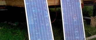
The charge controller is a very important component of the system in which solar panels create electric current. The device controls the charging and discharging of batteries. It is thanks to him that the batteries cannot be recharged and discharged so much that it will be impossible to restore their working condition.
You can make such controllers yourself.
Homemade controller: features, components
The device is designed to work with only one solar panel, which creates a current of no more than 4 A. The capacity of the battery, the charging of which is controlled by the controller, is 3,000 A*h.
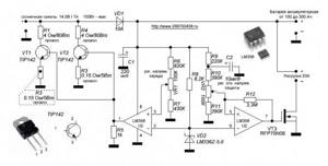
To manufacture the controller, you need to prepare the following elements:
- 2 microcircuits: LM385-2.5 and TLC271 (is an operational amplifier);
- 3 capacitors: C1 and C2 are low-power, have 100n; C3 has a capacity of 1000u, designed for 16 V;
- 1 indicator LED (D1);
- 1 Schottky diode;
- 1 SB540 diode. Instead, you can use any diode, the main thing is that it can withstand the maximum current of the solar battery;
- 3 transistors: BUZ11 (Q1), BC548 (Q2), BC556 (Q3);
- 10 resistors (R1 – 1k5, R2 – 100, R3 – 68k, R4 and R5 – 10k, R6 – 220k, R7 – 100k, R8 – 92k, R9 – 10k, R10 – 92k). They can all be 5%. If you want greater accuracy, you can use 1% resistors.
Types used in practice
At the industrial level, two types of electronic devices have been launched and are being produced, the design of which is suitable for installation in a solar energy system:
- PWM series devices.
- MPPT series devices.
The first type of controller for a solar battery can be called “old man”. Such schemes were developed and put into operation at the dawn of the development of solar and wind energy. The operating principle of the PWM controller circuit is based on pulse width modulation algorithms. The functionality of such devices is somewhat inferior to the more advanced devices of the MPPT series, but in general they also work quite effectively.
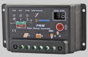
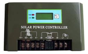
One of the models of solar station battery charge controller popular among users, despite the fact that the device circuit is made using PWM technology, which is considered outdated
Designs using Maximum Power Point Tracking technology (tracking the maximum power limit) are distinguished by a modern approach to circuit solutions and provide greater functionality. But if we compare both types of controller and, especially, with a bias towards the domestic sphere, MPPT devices do not look in the rosy light in which they are traditionally advertised.
MPPT type controller:
- has a higher cost;
- has a complex configuration algorithm;
- gives a gain in power only on panels of a large area.
This type of equipment is more suitable for global solar energy systems.
A controller designed for operation as part of a solar power installation. It is a representative of the class of MPPT devices - more advanced and efficient
For the needs of an ordinary user from a domestic environment, who, as a rule, has small-area panels, it is more profitable to buy and operate a PWM controller (PWM) with the same effect.
How can some components be replaced?
Any of these elements can be replaced. When installing other circuits, you need to think about changing the capacitance of capacitor C2 and selecting the bias of transistor Q3.
Instead of a MOSFET transistor, you can install any other one. The element must have low open channel resistance. It is better not to replace the Schottky diode . You can install a regular diode, but it must be placed correctly.
Resistors R8, R10 are equal to 92 kOhm. This value is non-standard. Because of this, such resistors are difficult to find. Their full replacement can be two resistors with 82 and 10 kOhm. They must be turned on sequentially .
Conclusions and useful video on the topic
The industry produces devices that are multifaceted in terms of circuit designs. Therefore, it is impossible to give unambiguous recommendations regarding the connection of all installations without exception.
However, the main principle for any type of device remains the same: without connecting the battery to the controller buses, connection to photovoltaic panels is unacceptable. Similar requirements apply for inclusion in a voltage inverter circuit. It should be considered as a separate module connected to the battery via direct contact.
Principle of operation
If there is no current from the solar battery, the controller is in sleep mode. It doesn't use a single watt from the battery. After sunlight hits the panel, electric current begins to flow to the controller. It should turn on. However, the indicator LED along with 2 weak transistors turns on only when the current voltage reaches 10 V.
Once this voltage is reached, current will flow through the Schottky diode to the battery . If the voltage rises to 14 V, amplifier U1 will start working, which will open the MOSFET transistor. As a result, the LED will go out and two low-power transistors will close. The battery will not charge. At this time, C2 will be discharged. On average this takes 3 seconds. After capacitor C2 discharges, the hysteresis of U1 will be overcome, the MOSFET will close, and the battery will begin to charge. Charging will continue until the voltage rises to the switching level.
Charging occurs periodically. Moreover, its duration depends on the charging current of the battery and how powerful the devices connected to it are. Charging continues until the voltage reaches 14 V.
The circuit turns on in a very short time. Its activation is influenced by the charging time of C2 with current, which limits transistor Q3. The current cannot be more than 40 mA.
Simple controller for solar battery
This time I decided to make an automatic machine that automatically turns on the LED lighting in the garden gazebo. Since there is no outlet nearby, and constantly pulling an extension cord is quite tedious, I decided to power the LEDs from a battery with recharging from solar cells.
A very similar solar cell driver was previously described that illuminates a glass shelf in a cabinet. Using this driver would pose a problem because we need more light to illuminate a gazebo than to illuminate a glass shelf. Also, the use of a more powerful light source will quickly discharge the battery, which can fail as a result of deep discharge of the elements in the battery.
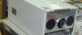
Transistor tester / ESR meter / generator
Multifunctional device for testing transistors, diodes, thyristors...
More details
To prevent this, I decided to create a simple driver with protection against too deep battery discharge based on an adjustable zener diode TL431. In turn, the solar cells also serve as a light sensor, which greatly simplifies the entire circuit.
The printed circuit board measures 40mm by 45mm. Additionally, two mounting holes have been added. The entire device is powered by three Ni-MH batteries (1.2V/1000mAh). A solar battery with a nominal voltage of 5 volts and a maximum output current of up to 80 mA is used for charging. The solar battery charges the batteries through the rectifier diode D1. The circuit does not have protection against overcharging the battery due to the fact that in such a configuration, overcharging is simply impossible.
A fully charged battery should have a voltage of about 4.2-4.35 V. The solar cell produces a voltage of 5 V, but there is a drop in the rectifier diode of about 0.7 V, which gives us a voltage of 4.3 V. Transistor Q1 is responsible for turning on the light night time and turn it off during the day. The base of this transistor is connected through a 2.2 kOhm resistor to the positive pole of the solar cell.
When the solar cell is not producing electricity or is too small, transistor Q1 is turned off. Then the current from the pin ("REF") of the zener diode TL431 will flow only through resistor R4, which creates a voltage divider together with resistors R2 and R3. Transistor Q2 controls the load in the form of LEDs. For the circuit to work correctly, we cannot ignore resistor R5, whose task is to pull the base of transistor Q2 to the positive of the power supply.
According to calculations for the available voltage, it turns out that the resistor should have a resistance of 100 Ohms. With such resistance, the circuit switches very quickly. But the problem is that this resistor has a fairly small value, and a very large current flows through it. The total current consumption is about 23 mA! I decided to replace this resistor with a resistor of a larger value. In the end, I installed a 1 kOhm resistor. Now the load shedding is not so fast, but the current consumption has been reduced to 8mA.
Of course, the current 8mA is only consumed when the solar cell is in a dark place - that is, only at night when the LEDs are on. And this is the same maximum current (8 mA) that comes from the battery at a voltage of 4.2 V. I set the load cut-off voltage to 2.9 V. The maximum voltage for one cell is 0.9 V, which when connecting three in series gives us 2.7 V, and therefore we still have 0.2 V left.
The circuit, after disconnecting the load (i.e. at 2.9 V and below), consumes only 50 μA. The same current will flow when the solar panel charges the batteries. The device is very responsive to light, but not so much that street lighting would interfere with twilight detection. From the moment sunset is detected until the LEDs turn on 100%, it takes approximately 2 minutes.
By removing transistor Q1, resistor R1 and rectifying diode D1 from the system, we obtain a simple circuit for protecting the battery from deep discharge. A similar circuit can be used to disconnect a Li-Ion or Li-Pol battery from charging. It can be used, for example, in a flashlight. It is also possible to create similar protection for other voltages; to do this, you need to calculate the voltage divider. Formulas and an example of calculation are here.
List of parts:
- resistors: 3×1k, 2.2k, 15k. 100k
- transistors: BC547, BC327 (or similar)
- Zener diode TL431
- diode 1N4007 (or similar)
- capacitor 100uF
(149.6 KiB, downloads: 1,494)
Source
Controller Michael Davis
This device is designed for more powerful solar panels. It does an excellent job of regulating the charging of batteries with the current produced by the wind generator. Since the device has a fairly simple structure, you can make it yourself.
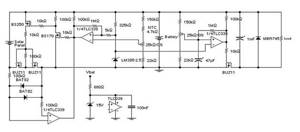
There are two variants of this controller . The first one is old and imperfect. The second is simpler and more effective. Its diagram is in the figure:
To create it you need to prepare:
- 2 regulators: 7805 (K142EN5A) (IC1) and NE555 (IC1);
- 2 standard buttons (РВ1 and РВ2);
- 2 LED bulbs. One is green, the other is yellow;
- 1 12 V automotive relay (RLY1). It is advisable to select a relay that allows you to switch currents of 30-40 A;
- 1 diode 1N4001. You can take any similar one;
- 2 tuning resistors 10K. In the diagram they are designated as R1 and R2. It is better if they are multi-turn. It is allowed to take resistors whose adjustment interval is 0-100K. However, 10K elements provide better adjustment;
- 3 resistors 1K Ohm 1/8 W 10% (labeled R3-R5);
- 1 resistor 330 Ohm (R6);
- 1 resistor 100 Ohm (R7);
- 2 transistors 2N2222 and IRF540. Designated as Q1 and Q2 respectively. Instead of the first transistor, you can take 2N3904, NTE123 or any other one, it has a bipolar NPN structure and similar characteristics. You can do the same with the second transistor;
- 2 capacitors 0.33uF and 0.1uF. Both are designed for 35 V. The type of capacitor can be any.
All these elements are placed on the board and soldered. After which the initial adjustment of the circuit . It consists of setting voltage levels at control points TP1 and TP2 . The voltage on the first should be 1.667 V, on the second – 3.333 V. These levels are set by setting the buttons. Also, a fuse for the appropriate current should be installed on each power circuit.
Controller connection methods
Considering the topic of connections, it should immediately be noted: for the installation of each individual device, a characteristic feature is working with a specific series of solar panels. So, for example, if a controller is used that is designed for a maximum input voltage of 100 volts, a series of solar panels should output a voltage no greater than this value.
Any solar power installation operates according to the rule of balancing the output and input voltages of the first stage. The upper limit of the controller voltage must correspond to the upper limit of the panel voltage
Before connecting the device, you need to decide on the location of its physical installation. According to the rules, the installation location should be chosen in dry, well-ventilated areas. Avoid the presence of flammable materials near the device.
The presence of sources of vibration, heat and humidity in the immediate vicinity of the device is unacceptable. The installation site must be protected from precipitation and direct sunlight.
Connection technology for PWM models
Almost all manufacturers of PWM controllers require that the devices be connected in the exact sequence.
The technique of connecting PWM controllers to peripheral devices is not particularly difficult. Each board is equipped with labeled terminals. Here you simply need to follow the sequence of actions
Peripheral devices must be connected in full accordance with the designations of the contact terminals:
- Connect the battery wires to the battery terminals of the device in accordance with the indicated polarity.
- Switch on the protective fuse directly at the point of contact of the positive wire.
- Attach the conductors coming from the solar panel battery to the controller contacts intended for the solar panel. Observe polarity.
- Connect a test lamp of the appropriate voltage (usually 12/24V) to the load terminals of the device.
The specified sequence must not be violated. For example, connecting solar panels first when the battery is not connected is strictly prohibited. By doing this, the user runs the risk of “burning” the device. Also, for PWM series controllers, it is not permissible to connect a voltage inverter to the controller load terminals. The inverter should be connected directly to the battery terminals.
Procedure for connecting MPPT devices
The general physical installation requirements for this type of device do not differ from previous systems. But the technological setup is often somewhat different, since MPPT controllers are often considered more powerful devices.
For controllers designed for high power levels, it is recommended to use large cross-section cables equipped with metal end caps for power circuit connections.
For example, for powerful systems, these requirements are supplemented by the fact that manufacturers recommend using a cable for power connection lines designed for a current density of at least 4 A/mm2. That is, for example, for a controller with a current of 60 A, you need a cable to connect to the battery with a cross-section of at least 20 mm2.
Connecting cables must be equipped with copper lugs, tightly crimped with a special tool. The negative terminals of the solar panel and battery must be equipped with adapters with fuses and switches. This approach eliminates energy losses and ensures safe operation of the installation.
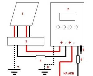
Block diagram of connecting a powerful MPPT controller: 1 – solar panel; 2 – MPPT controller; 3 – terminal block; 4.5 – fuses; 6 – controller power switch; 7.8 – earth bus
Before connecting solar panels to the device, you should make sure that the voltage at the terminals is equal to or less than the voltage that can be supplied to the controller input.
Connecting peripherals to the MTTP device:
- Switch the panel and battery switches to the “off” position.
- Remove the protective fuses on the panel and battery.
- Connect the battery terminals with a cable to the controller terminals for the battery.
- Connect the terminals of the solar panel with a cable to the controller terminals indicated by the corresponding sign.
- Connect the ground terminal to the ground bus with a cable.
- Install the temperature sensor on the controller according to the instructions.
After these steps, you need to reinsert the previously removed battery fuse and turn the switch to the “on” position. A battery detection signal will appear on the controller screen.
Next, after a short pause (1-2 minutes), replace the previously removed solar panel fuse and turn the panel switch to the “on” position. The device screen will show the voltage value of the solar panel. This moment indicates the successful launch of the solar energy installation.
Self-production
If a person has some knowledge in the field of electronics and electrical engineering, then you can try to assemble a controller circuit for solar panels and a wind generator with your own hands. Such a unit will be much inferior in functionality and efficiency to industrial serial models, but in low-power networks it may be quite sufficient.
A homemade control module must meet the basic conditions:
- 1.2P ≤ I × U. This equation uses the designations of the total power of all sources (P), the output current of the controller (I), the voltage in the system with a completely discharged battery (U);
- The maximum input voltage of the controller must correspond to the total voltage of the batteries without load.
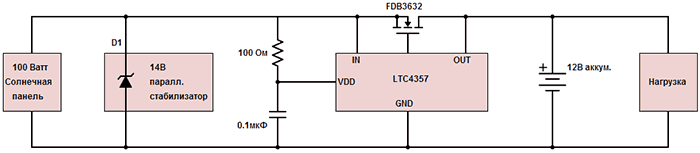
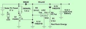
The simplest diagram of such a module will look like this:
The device, assembled by yourself, works with the following characteristics:
- Charging voltage – 13.8 V (may vary depending on current rating);
- Shutdown voltage – 11 V (configurable);
- Turn-on voltage – 12.5 V;
- The voltage drop across the keys is 20 mV at a current value of 0.5A.
PWM or MPRT type charge controllers are one of the integral parts of any solar system or hybrid system based on solar and wind generators. They ensure normal battery charging, increase efficiency and prevent premature wear, and can also be assembled with your own hands.
What is a charge controller and what types does it come in?
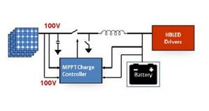
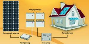
Each of the elements of the above diagram plays its role:
- The solar module perceives light radiation and converts it into direct electric current. The module itself consists of many semiconductors (photocells);
- The battery (battery pack) is used to accumulate and distribute energy supplied from the modules;
- The inverter is used to convert direct current into alternating current by changing the output frequency and voltage values in the network.
A logical question may arise here: “why then use a controller, since you can directly connect the solar module and the battery pack?”
If this is not done, then charging current will constantly flow to the battery terminals, which in turn will cause an increase in voltage. Sooner or later, depending on the type of battery, the voltage will reach a maximum value of 14.4 V, after which the process of recharging the battery and boiling off the electrolyte in it will begin. And this is a direct path to reducing the service life of the battery. You can control this process manually using a simple voltmeter and turn off the power at the right time. But in this case, the person will be constantly tied to the system and it will no longer be possible to call it autonomous. The controller is precisely the link in the chain that should automatically monitor the process of charging and distributing energy from the battery. In addition, it performs a number of other functions, the list of which depends on the specific model and type:
- Automatic connection of batteries and modules with a charging circuit;
- Selection of optimal charge accumulation modes;
- Full control of the process and, if necessary, disconnecting or connecting consumers;
- Support correct polarity;
- Protection against short circuits, power failure (break);
- Accounting for battery charge levels;
- Energy consumption control, etc.
For existing solar systems, you need to assemble them yourself or choose one of three existing types:
- On/Off;
- PWM (PWM);
- MPPT.
Main purpose
The solar battery charge controller is designed to maintain the charge level of the batteries, which also prevents them from being completely discharged or overcharged. Lead-acid batteries are usually connected to such devices due to their prevalence, however, it is possible to connect other types. The solar panel controller performs a large number of functions that ensure reliable and efficient operation. The main ones are:
- choosing the most efficient battery charging system;
- battery charge monitoring;
- automatic switching on and off;
- proper energy distribution;
- protection against overvoltage and circuit breakage.
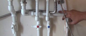
How to connect yourself
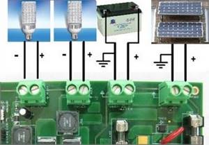
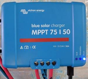
Connecting an MPPT charge controller for solar panels is quite simple. To do this, you should understand the basic connection diagram, be able to understand and navigate it, and also connect all the wires and elements with full respect for polarity, that is, connect “plus” to “plus”, and “minus” to “minus”.
In the figure below you can see special holes with a “plus” and a “minus”; in fact, you should correctly insert the necessary wires into them.
A more detailed diagram is presented below.
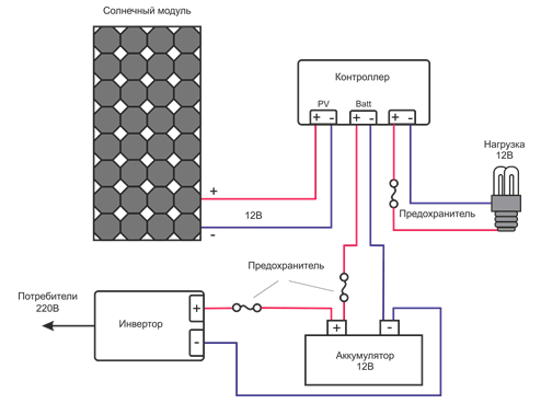
The connection diagram is quite simple, it is important to connect all the elements, observing the polarity, and it is also necessary to take into account that they are safely located in the house and do not threaten life. Anyone can cope with this task.
It is possible to connect several batteries, but here they must be connected in a mixed way, namely: a group of batteries is connected to each other in parallel, and to the controller in series. A similar diagram can be seen in the figure below.
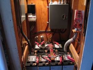
As can be seen from the diagram, the number of batteries is not limited. However, it should be understood that with such a number it is necessary to purchase an appropriate inverter that will be able to cope with such a large load.