Many properties are experiencing problems with hot water supply and heating. Oil boiler houses can solve them. Such installations are very popular today in the Russian Federation. This is due to the affordable cost, as well as low operating costs.
Oil and fuel oil may well serve as reserve or emergency fuel. Many models of fuel oil boiler houses are now characterized by fully automatic operation. At the same time, the most stringent safety requirements are still imposed on such equipment. For this reason, at the production stage of such boiler houses, developers must take into account strict government standards.
Start-up of the boiler plant
3.2.1.
Before lighting the boiler, it is necessary to carry out a pre-start check of the closure of the shut-off valves on the oil pipelines in front of the burners and ignition devices in accordance with the operating instructions. 3.2.2. Before starting up the boiler after an outage of more than 3 days, the serviceability and readiness to turn on the draft mechanisms of the boiler, its auxiliary equipment, measuring instruments and remote control of fittings and mechanisms, auto regulators must be checked, and the operability of protections, interlocks, operational communication equipment must be checked. triggering of the slam-shut valve. When downtime is less than 3 days, equipment, mechanisms, protection devices, interlocks, and measuring instruments on which repairs were carried out are subject to inspection. Identified malfunctions must be eliminated before starting the boiler.
3.2.3. Before starting the boiler, it is necessary to ensure the pressure of fuel oil and steam, air and draft in accordance with the requirements of the operating instructions.
The temperature of the fuel oil before mechanical and steam-mechanical nozzles must correspond to its viscosity of no more than 2.5 °VU, and before steam and rotary nozzles - no more than 6 °VU.
3.2.4. Immediately before igniting the burners, the firebox and gas ducts (including recirculation) must be ventilated for at least 10 minutes with the gas-air duct dampers open and the air flow rate at least 25% of the nominal. The conditions that ensure the required air flow for ventilation must be specified in local regulations. At the same time, the “warm box” must be ventilated.
3.2.5. Ventilation of boilers operating under pressurization, as well as hot water boilers in the absence of smoke exhausters, should be carried out by blower fans and gas recirculation smoke exhausters.
3.2.6. The firing of boilers with balanced draft should be carried out with the smoke exhausters and blower fans turned on, and the kindling of boilers operating under pressurization should be carried out with the blower fans turned on.
3.2.7. The firing of a sulfur fuel oil boiler must be carried out with the air heating system in front of the air heater previously turned on.
3.2.8. According to explosion safety conditions, the firing of a fuel oil boiler can begin with the ignition of any burner or group of burners and be carried out in the sequence specified in the boiler installation operating instructions.
3.2.9. If any of the burners goes out or does not ignite when ignited, the supply of fuel oil to it must be immediately stopped and the ignition device must be turned off. Ignition of the boiler can continue by igniting subsequent burners if at least one burner remains in operation. If there is not a single burner left in operation, then you should be guided by the instructions in paragraph. The switched-off burner must be re-ignited after eliminating the reasons for its extinguishing or non-ignition.
3.2.10. When lighting the boiler, the burners must be ignited using an ignition device; The ignition device must be switched off after stabilization of the burner flame.
(New edition. Change No. 2)
3.2.11. In the event of a torch break in the furnace, the fuel supply to the boiler must be immediately stopped and the pilot lights must be turned off. Only after ventilating the firebox and flues for 10 minutes and eliminating the reasons for the firebox going out can you begin to kindle.
Popular models of oil boilers
Among the liquid fuel boilers that can operate on fuel oil, the following models can be distinguished:
- All boilers from Protherm (Slovakia) are named after animals. Liquid fuel boilers are represented by the Bizon series. The units can be equipped with a mounted railway or gas burner, which are purchased separately. The price of such heating units with an automation unit without a burner is 36-55 thousand rubles.
- Domestic combination boilers De Dietrich GT can work with both a gas and an attached pressurized liquid fuel burner. The boilers themselves are made of corrosion-resistant cast iron, resistant to thermal and shock loads. The cost of such boilers is 70-90 thousand rubles, the price of an iron burner is 35-38 thousand rubles.
- Fuel oil is used as fuel in KV type steam boilers, used in production for technological needs and heating.
The main disadvantages of liquid fuel, including fuel oil, boilers are the dependence on electricity supply and the need to install special tanks for fuel reserves.
Advantages of liquid fuel boilers
- There are quite obvious advantages of liquid fuel boilers used in industries related to fuels and lubricants. For private homes, the advantages of boilers of this type may raise questions:
- Liquid fuel boilers have a high efficiency of 86 to 98%. This is a good indicator, and it is very close to the indicators of gas boilers;
- An undoubted advantage of diesel boilers, unlike gas boilers, is that you do not need permits (approvals) to install the boiler. Although the combustion room will still have to be equipped;
- Diesel boilers are produced in the most autonomous configurations. Automation of boilers and automatic fuel supply allow minimizing the presence of a person for maintenance;
- Another plus is the ability to quickly and easily, by changing the boiler burner, switch to working with natural gas;
- Although there are no omnivorous boilers, diesel boilers can operate on alternative types of liquid fuel, as indicated in the documentation for the boiler;
- Liquid fuel boilers can fit into any heating system and can work with any coolant (water and antifreeze).
Advantages of an oil boiler house
The obvious advantages (advantages) of a block-modular fuel oil boiler house distinguish it favorably from analogues (for example, solid fuel):
- Factory readiness. High-quality assembly in production conditions.
- Automation. In automated fuel oil boiler houses, equipment is optimally selected and distributed, and all sensors and systems operate without the help of technical personnel.
- Economical. No capital construction costs, no permanent operator presence and low fuel costs.
- Safety. Minimal risk of fire.
It is also worth noting the minimum production time for a fuel oil boiler room - you can always find out more about this from specialists.
Oil farming
The oil farm consists of an open oil warehouse and a hardware room. An oil warehouse usually has above-ground metal tanks mounted on foundations of individual reinforced concrete posts. The open oil warehouse is fenced off from the rest of the territory by an earthen rampart 1.2 m high with a continuous sod. To drain surface water and drain oil in the event of a tank failure, the surface of the warehouse has a slope towards the sewer wells, from which it is planned to release water or oil beyond the TPP site. The oil facility must have four turbine oil tanks and four insulating oil tanks. The capacity of each tank is no less than the capacity of a railway tank - 70 m3, in addition, the permissible minimum capacity depends on the capacity of the oil system of the turbine unit and transformer. For emergency drainage of turbine oil, a special tank is provided at the power plant.
Rice. 9.6. Scheme of a vortex furnace with intersecting jets: 1 - cold radiation surface; 2 - firebox surface covered with refractory coating; 3 - fuel supply
Receiving and draining device
A railway unloading platform for receiving railway tanks with fuel oil is constructed in the form of two longitudinal walls, between which a drain tray is installed. The walls are made of concrete blocks. Depending on the height of the overpass wall and the load-carrying capacity of the tanks, reinforced concrete belts are made along the bottom and top of the walls.
When supplying fuel oil in tanks with a lifting capacity of 50-60 tons, the trestle with a drain tray can be made of a lightweight design without installing a reinforced concrete bottom. A more advanced overpass has also been developed with a drain tray made of reinforced concrete I-beam elements 5.6 m long, weighing 12.5 tons each, representing the walls of the overpass (Fig. 5.16). The lower bars of the walls are connected by loop joints, which are monolid and form the bottom. The walls along the top in the longitudinal direction are connected by loop joints. To avoid freezing of the base, slag filling is carried out under the bottom of the tray. The fuel oil drain tray has a longitudinal slope of 0.01 towards the center of the overpass, from where the fuel oil is drained into an intermediate container. Outlet trays are made of structures similar to those of a railway overpass.
The receiving capacity of the main fuel oil facility must be designed for at least 15% of the capacity of tanks installed for unloading. Typically, the receiving tank consists of two underground tanks with a capacity of 600-1000 m 3 each. To service the tanks, a special overpass is constructed from prefabricated reinforced concrete elements.
Characteristics of fuel oil
There are two types of heating oil used in boiler houses:
- medium fuel grades M40 m M40V;
- heavy fuel – M100, M100V.
In ship installations, light fuel grades F5 and F12 are used.
Elementary composition of fuel oil:
- high carbon content – up to 87%;
- hydrogen – up to 12.5%;
- oxygen and nitrogen – up to 0.5%.
Fuel oil also contains sulfur, which when burned forms sulfur dioxide. The use of this fuel is complicated by the possible presence of water, which leads to a decrease in heat generation and causes corrosion of pipelines and equipment.
The density of fuel oil obtained by direct distillation is less than the density of water; its sedimentation period lasts 4-8 days. Cracking fuel oil has a density that exceeds that of water.
Operational characteristics of fuel oil:
- Viscosity, characterized by the degree of fluidity, is measured by a viscometer. The conditions of transportation, pumping, and combustion of this fuel depend on the value of this parameter.
- The pour point is the temperature at which fuel oil loses its fluidity and becomes a stationary mass; this value is in the range of 10-360C.
- The flash point of a fuel is the temperature at which fuel oil vapors combine with air to form a flammable mixture that ignites when a fire is brought to it. For different brands it ranges from 90-1500C. The self-ignition temperature is 3500C.
To supply fuel oil to the burner, it must be heated to 80-1200C. This process is only applicable to fuel that is under pressure in closed containers - pipes and coils.
Boiler plant
2.3.1. The design of the boiler furnace and the placement of burners in it must ensure the possibility of maintaining a stable combustion process and monitoring this process and exclude the possibility of the formation of stagnant and poorly ventilated zones.
2.3.2. The introduction of recirculating gases into the combustion chamber should not disrupt the stability of the combustion process.
2.3.3. For newly designed boiler plants with a steam capacity of at least 60 t/h, equipped with explosion safety valves, the frames and metal structures of the firebox and gas ducts must be designed for pressure inside the firebox and gas ducts exceeding atmospheric pressure by at least 200 kgf/m2 (2000 Pa). The frames of the firebox and flue ducts of newly designed boilers with a steam capacity of 60 t/h and above, the equipment of which with explosion safety valves is optional, must be designed for internal pressure exceeding atmospheric pressure by at least 300 kgf/m2 (3000 Pa), for installations operating under vacuum, and internal pressure exceeding the maximum operating pressure by at least 300 kgf/m2 (3000 Pa), for units operating under pressurization.
2.3.4. Lookouts must be installed in the boiler firebox to allow observation of combustion and eliminate the possibility of flame emission. The doors of manholes, hatches and peepholes in the furnace and gas ducts of the boiler must be tight and have strong locks that prevent their spontaneous opening.
2.3.5. Gas ducts on the combustion products exhaust line and gas ducts for recirculating combustion products into the boiler furnace must not have unventilated areas in which flammable gas could linger or accumulate.
2.3.6. The boiler air path from the air heater to the burners must be designed in such a way that it can be completely ventilated by blowing into the firebox.
2.3.7. On boilers, the volume where the collectors and boiler hangers are located (“warm box”) must be ventilated.
2.3.8. The areas for servicing fuel oil nozzles, as well as above the exhaust openings of the explosion safety valves of the furnace and gas ducts must be solid.
2.3.9. At boiler plants with a steam capacity of less than 60 t/h, except for boilers made of membrane gas-tight panels and boilers with single-pass gas movement, explosion safety valves are installed in cases provided for by the current “Rules for the design and safe operation of steam and hot water boilers.”
In boiler installations with a steam capacity of 60 t/h and above, explosion safety valves in the furnace and throughout the air and gas ducts up to the chimney may not be installed unless this is provided for in the boiler design.
Gas ducts from the boiler to the chimney must be designed for operating pressure (vacuum).
2.3.10. Boilers must be equipped with means for cleaning convective heating surfaces and air heaters.
2.3.11. Air heaters of boilers must be equipped with fire extinguishing means. Water should be used as the main fire fighting agent. To extinguish a fire in the convection shaft of a boiler with a tubular air heater, it is allowed to use superheated or dry saturated steam instead of water.
2.3.12. The pilot burners of operating boilers must be equipped with ignition protection devices. The remaining burners of operating boilers must be equipped with ignition (IPD) or ignition-protective devices (IPD).
All burners of newly commissioned boilers must be equipped with an emergency protection system.
2.3.13. A looker should be installed on each burner, allowing you to observe the torch of a given burner and the condition of the nozzle.
2.3.14. It must be possible to turn off the fuel supply to the burner manually from the maintenance platform.
2.3.15. The attachment of the nozzle to the block must ensure a tight connection and quick removal and installation of the nozzle. The use of a gasket in the connection between the injector and the block is not recommended.
Boiler houses using fuel oil
Oil-fired boiler systems are often the technically best option when solving the problem of heating and hot water supply to various facilities (residential, administrative, industrial) that are not connected to the central gas supply. Boiler houses using fuel oil/oil are popular in the Russian Federation due to their main advantages - fairly low fuel costs and low operating costs (compared to solid fuel boiler houses).
Fuel oil or oil can also be used as a reserve or emergency fuel in multi-fuel boiler houses to ensure uninterrupted operation of the boiler house in the event of interruptions in the supply of the main type of fuel (for example, gas).
Modern fuel oil boiler houses are manufactured fully automated, which eliminates the need for the constant presence of maintenance personnel and, accordingly, saves on operating costs.
Boiler houses operating on fuel oil are subject to increased safety requirements. Therefore, when designing and manufacturing fuel oil boiler houses, the specialists of the GasSintez Plant are guided by the following requirements:
- RD 34.03.351-93 “Explosion safety rules when using fuel oil in boiler installations”
- SO 34.23.501-2005 “Guidelines for the operation of fuel oil facilities at thermal power plants”
- SP 89.13330.2012 “Boiler installations. Updated edition of SNiP II-35-76"
Installation of boiler houses using fuel oil
Fuel oil boiler houses are classified as liquid fuel boiler houses. The composition of the equipment of such boiler houses is determined by the requirements for the power of the boiler house, the required volume of fuel oil reserves, the method of fuel delivery and the method of placing fuel oil storage facilities.
The GazSintez plant designs and manufactures block-modular boiler houses operating on fuel oil. The block-modular design of boiler houses ensures easy transportation, since the dimensions of one block module correspond to the overall dimensions of vehicles (railway platforms, trawls). Modular boiler rooms are delivered to the site of operation in full factory readiness, that is, all equipment is installed at the factory inside the boiler room body. At the construction site, you only need to mount the block modules (if the boiler room consists of several block structures with high power) into a single structure and connect to external networks.
The block module of an oil boiler house is a welded metal frame covered with sandwich panels or profiled sheets with thermal insulation. The housing is equipped with a window, a ventilation grille and a door.
The peculiarity of fuel oil boiler houses is the formation of combustion products, which must be removed from the boiler room. To do this, it is necessary to install a chimney, which can have various designs and which removes exhaust gases and disperses them into the atmosphere at a safe distance.
Our specialists produce automated block-modular boiler houses using fuel oil, which minimize the participation of working personnel. Remote control of the boiler room is also possible. Boiler control cabinets are manufactured according to our own designs and optimally meet operational requirements.
The general layout of a fuel oil boiler room consists of:
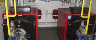
- boiler/boilers
- oil burner with nozzles
- heat exchanger
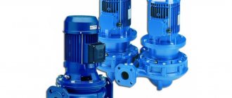
- circulation, network, make-up and other pumps for water and fuel oil supply systems to the burner
- fuel oil storage (tanks)
- fuel oil pipelines for supplying fuel to the storage facility and from the storage facility to the boiler room
- fuel oil unloading system
- coarse and fine fuel filters
- water treatment equipment
- expansion membrane
- internal piping
- control and measuring instruments for commercial and technological accounting
- shut-off and safety valves
- automation and dispatch system for fuel oil boiler house
- security and fire alarms
- chimney system and chimney
Fuel oil production of block-modular boiler houses
The efficient operation of fuel oil boiler houses lies in the high-quality combustion of fuel. The combustion of fuel oil occurs in three stages: 1 - atomization of fuel into tiny drops using nozzles, 2 - evaporation of fuel oil vapor and mixing of flammable vapors and air, 3 - ignition and combustion of the mixture. The quality of combustion largely depends on the brand of fuel oil, its quality, the properties of the nozzles and the normal air supply to the ignition system.
Delivery of fuel oil to the boiler room can be carried out by rail or road transport. Depending on the delivery method, the fuel oil storage complex includes a different set of equipment. So, for example, when delivering fuel oil by railway, it is necessary to provide for the possibility of constructing access roads and installing a loading and unloading rack, as well as fuel supply pipelines to the fuel storage tank. And when delivering fuel oil by vehicle, heating the fuel when draining is not required, since it arrives already heated. To complete a fuel oil facility, you should also take into account the characteristics of fuel oil, namely its viscosity. F40 and M100 grades of fuel oil are used as fuel in fuel oil boiler plants. The method of transportation, draining, pumping and combustion depends on whether low-viscosity or high-viscosity fuel oil is used in the boiler room. For example, for high-viscosity fuel oils, heating equipment is required, since the fuel oil at the entrance to the boiler must have a temperature of +120ºС, and when pumping +30ºС-+60ºС. Therefore, in fuel oil boiler houses there must be a boiler for heating fuel oil or other equipment for heating fuel oil: steam submersible oil heaters in a storage tank, electric heaters, heaters as part of a loading and unloading rack, portable coil heaters, etc.
When designing boiler houses using fuel oil, it is necessary to provide for the possibility of installing equipment for dosing reagents and additives into the system to prevent the formation of deposits on pipelines and other elements.
The fuel oil economy of block boiler houses includes one tank (if fuel oil is an emergency or reserve fuel) or more than two tanks (if fuel oil is the main fuel) for storing fuel oil sufficient for autonomous operation of the boiler room for the required amount of time. The fuel storage warehouse can be located above ground or underground, near or far from the boiler house itself. Accommodation options are selected based on the Customer’s technical requirements and state standards.
The construction of fuel oil boiler houses is possible without installing fuel storage tanks if it is constantly supplied through pipelines from the central supply system, but this option for constructing a fuel oil boiler house is quite rare.
Thus, the fuel oil facility includes a fuel oil unloading system, a storage system (tanks) and a system for supplying fuel oil to the boiler nozzles.
The fuel supply system to the boiler room has a reverse scheme, which involves returning fuel oil to the tanks if the volume of fuel burned is less than the volume of incoming fuel. Fuel oil is supplied to the boiler room through the use of pumps.
Special attention should be paid to installing filters for coarse and fine purification of fuel oil: the fuel entering the boiler should not contain mechanical impurities, inclusions and other substances that reduce combustion efficiency and can damage the boilers.
In the event of an emergency use of a fuel oil boiler room (accident on a gas pipeline), when it is necessary to quickly provide facilities with heat and water, fuel oil can be supplied to the boiler room directly from a tanker without installing storage tanks.
Calculation of block-modular fuel oil boiler houses produced by the GasSintez Plant
To select equipment for an oil boiler house and calculate its cost:
- contact the Factory by phone 8-800-555-4784
- send a Questionnaire for ordering a fuel oil boiler room by email
- Please indicate your contact information in the “Request a Quote” form so that our specialists can contact you.
Our specialists offer you the following range of services:
- design of a block-modular boiler house using fuel oil
- production of fuel oil boiler houses
- reconstruction of fuel oil boiler houses
- conversion of boiler houses to fuel oil
- delivery of block-modular fuel oil boiler houses
- installation and commissioning of fuel oil boiler houses in block design
Normal operation of the boiler system
3.3.1. During boiler operation, it is necessary to monitor:
maintaining the combustion regime in accordance with the regime map, preventing the operation of the furnace with chemical incomplete combustion of fuel and the removal of soot particles from the furnace;
fuel oil pressure after the control valve, not allowing it to decrease below the limit specified in the regime map;
the temperature of the fuel oil in front of the nozzles, not allowing it to decrease below the values determined in accordance with the instructions in paragraph;
a torch, especially when switching from one type of fuel to another, preventing it from going out.
3.3.2. Cleaning the heating surfaces of an operating boiler must be carried out in accordance with the requirements of the operating instructions.
3.3.3. Inspection of fuel oil pipelines in a boiler room must be carried out regularly according to an approved schedule. The inspection periods are established in accordance with the “Rules for the technical operation of electrical stations and networks.”
3.3.4. At least once a shift, an external inspection of operating injectors should be carried out, and if necessary, they should be replaced.
Before installation on the boiler, oil nozzles must be tested on a water stand to check their performance and atomization quality.
At the power plant (boiler house), there must be a person responsible for the stand and testing of fuel oil nozzles on it.
3.3.5. While walking around a working boiler, it is prohibited to open hatches or manholes on the boiler, with the exception of briefly opening inspection hatches and peepholes when standing to the side of them.
Dead-end circuit
It is used when burning relatively low-viscosity fuel oils, when the boiler room operates at stable loads that exceed the average (Fig. 9.3). Fuel for pumps 3
comes from supply tank
5.
When installing a supply tank in the boiler room, it must be closed, with a volume of no more than 5 m3. It is not permitted to install a supply tank above boilers and economizers. The circuit must provide for the circulation of fuel oil from the pressure fuel oil pipeline of the pumps to the supply tank.
When the boilers are operating, the valves on the fuel oil lines behind the boiler burners are closed. When the boilers are stopped, these valves open and the recirculation line to the supply tank comes into operation. Fuel oil in the supply tank comes from the main tanks of the fuel oil storage facility.
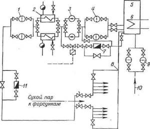
Rice. 9.3. Dead-end liquid fuel supply circuit.
1
— fine filter;
2
and
6
—car heaters;
3
- pump;
4
and
9
- coarse filters;
5 — consumable container; 7 and 11 - fuel oil meters; 8 - circulation section; 10
— fuel supply from the main tank.
Fuel consumption is determined by a fuel oil meter 11,
Both rotational meters and special restriction devices can be used as fuel oil meters. Accounting for fuel consumption in a dead-end scheme is simpler than in a circulation scheme: accounting is carried out using one fuel oil meter in front of the boilers.
Topic 11. Liquid fuel burners
Oil nozzles (mechanical, with a spraying medium, combined steam-mechanical, rotary): design, principle of operation, scope, advantages and disadvantages. Air guide devices.
Oil nozzles.
The nozzle is one of three devices (along with the air guide device and the tuyere - embrasure) that form the burner.
Thermal power plants are supplied with gas from gas distribution stations (GDS) through gas distribution points (GRP) (Fig. 5.1.) The latter, together with the gas pipeline system, make up the gas supply of thermal power plants. At gas-oil condensing power plants with a capacity of up to 1200 MW and gas-oil thermal power plants with a steam flow rate of up to 4000 t/h, there can be one hydraulic fracturing unit, and at other power plants their number must be at least two. The performance of hydraulic fracturing at power plants where gas is the main fuel is calculated based on the maximum gas consumption of all working boilers, and at power plants that burn gas seasonally, based on gas consumption for the summer mode, hydraulic fracturing is located in separate buildings or under sheds on the territory of the power plant. Gas is supplied to each hydraulic fracturing unit via one gas pipeline (without a backup one) from a GDS power station located outside the territory. Gas pressure before the hydraulic fracturing is 0.6-1.1 MPa, and after the hydraulic fracturing its required value is determined by the pressure loss to the boiler furthest from the hydraulic fracturing and the required gas pressure in front of the burners and is usually 0.13–0.2 MPa.
Rice. 5.1.
I—
shut-off valve, 2—flow meter, 3—filter, 4—pressure regulator, 5—safety valve, 6—bypass line, 7—gas flow regulator; 8—pulse shut-off valve, 9—plug valve.
The hydraulic fracturing system has working gas pipeline lines, low-flow lines that are switched on when gas consumption is low, and a reserve line with manual control of the valves. On working lines and low-flow lines, automatic pressure regulators and protective regulators are installed, operating on the “after themselves” principle. Protective regulators are adjusted to higher pressure compared to the operating pressure and are completely open when operating within the design range.
Within the gas distribution zone and up to the boilers, gas pipelines are laid above ground. The gas supply from each gas distribution unit to the boiler room main and from it to the boilers is not reserved and can be carried out as a single line. The gas distribution manifold of the boilers is laid outside the boiler room building.
When filled with gas, gas pipelines must be blown through the discharge candles until all the air is displaced, and when emptying the gas, they must be blown through with air until all the gas is displaced. These requirements are due to the fact that when the volumetric concentration of natural gas in the air is 0.05-0.15 (5-15%), an explosive mixture is formed. From the waste candles, the gas is released to places from where it cannot enter buildings and where the possibility of its ignition is excluded from any source of fire. Only steel fittings are installed on gas pipelines.
Fuel oil facilities of boiler houses
Thermal diagram of a boiler room with steel hot water boilers
Thermal diagram of a boiler room with steel steam boilers
Thermal diagrams of boiler installations
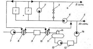
In Fig. 53 shows a basic thermal diagram of a heating and industrial boiler house with water tube boilers operating on a closed heat supply system. The thermal circuit is typical for boiler houses with DKVR, , and other medium-pressure boilers that have pre-boiler water treatment.
Rice. 53. Thermal diagram of a boiler room with steel steam boilers:
1 – boiler; 2 – main steam line; 3 – reduction unit; 4 – steam-water heater; 5 – condensate cooler; 6 – jumper; 7 – network pump; 8 — condensate tank; 9 – condensate pump; 10 – make-up pump; 11 – deaerator; 12 – steam feed pump; 13 – electrically driven feed pump; 14 – vapor cooler; 15 – purge water cooler; 16 – HVO; 17 – raw water heater; 18 – purge well; 19 – raw water pump; 20 – continuous blowing separator; 21 – economizer; 22, 23, 24 — pressure reducing valve; 25 – steam pipeline for own needs.
Steam from boilers 1 enters the main steam line 2, from where it is sent to production to heat water in a network unit (SU).
The control system consists of a steam-water heater, a condensate cooler 5 and a network pump 7 and a reduction unit 3. Water from the heating network with a design temperature of 70 0C is first heated by condensate in the condensate cooler, and then, finally, by steam in a steam-water heater and with a design temperature of 130-150 0C enters the heating network. The movement of water in the heating network and through the heat exchangers of the control system is carried out by the network pump 7.
The control unit receives steam from a pressure reduction unit, which reduces the steam pressure to 0.6-0.7 MPa and maintains it constant when the steam flow rate changes. To avoid steam entering the heating network when the heater tubes depressurize, the steam pressure should be 0.1-0.2 MPa lower than the supply water pressure.
Having given up its heat to the network water, the steam in the installation turns into condensate, which has a pressure of 0.6-0.7 MPa and a temperature of 160-165 0C. To prevent condensate from boiling in deaerator 11, the condensate is cooled in 5 to a temperature of 80-90 0C. To ensure reliable operation of the control system, the number of steam-water heaters, condensate coolers and network pumps is accepted at least two for each type of equipment.
Condensate from production is returned to the condensate tank 8, from where it is supplied to the deaerator by the condensate pump 9.
Water losses in the boiler house and heating network are replenished with source water using a pump19.
Before entering the boilers, raw water is softened in chemical water treatment filters 16 (CWO) and freed from corrosive gases in the feed deaerator 11.
To prevent fogging of pipelines and equipment, the source water before the chemical treatment is heated with steam to 15-20 0C in heat exchanger 17.
In deaerator 11, gases are released from boiling water at a temperature of 102-104 0C and a pressure of 0.12 MPa. To heat the water, steam is used from the auxiliary steam line 25 with a pressure of no more than 0.2 MPa.
Steam boilers are supplied with water from a group feed unit, including centrifugal pumps 13 with an electric drive and steam piston pumps 12. The pumps take water from the deaerator and supply it to the boilers through individual feed water economizers 21.
When the power supply to the boiler room is interrupted, water is supplied to the boilers by a steam pump, which is necessary to prevent the boilers from failing due to overheating of their heating surfaces (to cool the boilers).
The operation of steam boilers is accompanied by continuous blowing of their upper drums. To reduce heat losses with blowdown water, a blowdown separator 20 and a blowdown water cooler 15 are used. The pressure in the separator is maintained at 0.17-0.2 MPa, which is significantly lower than the pressure in the boiler. Therefore, boiler water boils in the separator and steam is formed with a pressure of 0.17-0.2 MPa and a temperature of 115-120 0C. The steam is discharged into the deaerator, and the water is cooled to 60-40 0C in heat exchanger 7 and discharged into the blowdown well 18. Periodic blowdown water also comes here. Water is discharged from the blow-off well into the facility's sewage system. The temperature of the drained water is limited by local conditions and, as a rule, should not exceed 60 0C.

Steel hot water boilers operate on water that has undergone chemical treatment and deaeration. Due to the lack of steam in the boiler room, vacuum deaeration is used.
To protect boilers from low-temperature gas corrosion, a network water recirculation system is used around the boilers, which ensures heating of water to 70 - 100 0C at the entrance to the boilers by mixing hot water from the boilers into the return network water.
Rice. 54. Thermal diagram of a boiler room with steel hot water boilers:
1 – boiler; 2 – recirculation pump; 3 – jumper; 4 – supply pipeline; 5 – return pipeline; 7 – raw water pump; 8 – heater; 9 – HVO; 10 – heater; 11 – deaerator; 12 – transfer pump; 13 – storage tank; 14 – charging pump.
The boilers are connected in parallel to the supply 4 and return 5 lines of the heating network (Fig. 54). Cooled water with a temperature of 70 0C is taken from the return line by network pumps 6 and pumped through the boilers. Water heated in boilers at a temperature of 150 0C is supplied to consumers through the supply pipeline. When the temperature of the return network water decreases to values at which low-temperature gas corrosion occurs in the tail heating surfaces of the boilers, part of the hot water is supplied to the inlet of the boilers using recirculation pump 9.
To regulate the temperature of the direct network water, bypass line 3 is used, through which cooled return network water is mixed into the hot water.
In large boilers, for example, the PTVM type, each boiler receives water from its own network pump and has individual recirculation and mixing systems. In such cases, one backup network pump, common to all boilers, is additionally installed.
Losses and leaks of water from the heating network are compensated by softened and deaerated water, which is supplied by the make-up pump 14 to the suction manifold of the network pumps.
To prepare make-up water, raw water is used, which is supplied to the boiler room by pump 7. Before the water softening filters 9 and before the deaerator 11, the water is initially heated with hot water from the boilers in heat exchangers 8 and 10. Chemically purified water is introduced into the deaerator, superheated relative to the saturation temperature in the deaerator at 6 – 9 0С, which is necessary for its intensive boiling at a temperature of 70 0С at a pressure of 0.03 MPa. The vacuum in the deaerator is created by water-jet ejectors.
When a boiler room operates on an open heating system, the thermal circuit includes tanks - hot water accumulators and pumps that pump deaerated water into these tanks.
Very often, in boiler houses that burn fuel oil, steam generated in steam boilers installed in boiler houses is used to heat the fuel oil and deaerate the water. The use of steam makes it possible to increase the reliability of the deaerators and increase the intensity of heating of fuel oil compared to hot water used for these purposes
17. Fuel economy of boiler houses
17.1. Fuel economy of boiler houses operating on solid fuel
Storage and supply of coal to the boiler room. Coal is delivered to the supply warehouse by rail or road transport. In a warehouse, coal is stored in stacks, the height of which depends on the grade of coal. For hard coal, the height of the stacks is limited to 6–7 meters. Coals prone to spontaneous combustion are stored in stacks no more than 4 m high. Passages for transport are left between the stacks. To combat fires, warehouses are equipped with fire extinguishing equipment.
The supply of coal to the boiler room and to the boilers depends on the method of burning coal and is done manually (carts, wheelbarrows, trolleys) or using various mechanisms (forklifts, bulldozers, conveyor belts, lifts, etc.).
Boilers with semi-mechanical and mechanical fireboxes are equipped with individual bunkers, from which coal is supplied to the coal throwers into the firebox. Coal is delivered to bunkers in most cases using a bucket lift (Fig. 55).
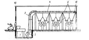
Rice. 55. Fuel supply diagram with a bucket lift:
1 – crusher; 2 – ladle; 3 – vertical guides; 4 – horizontal guides; 5 – bucket tippers; 10 – winch.
Ladle 2 is mounted on a trolley, which moves along rails using a traction rope and an electric winch 10. The ladle is loaded with crushed coal coming from crusher 1, rises to the level of the boiler hoppers and moves along horizontal guides 4 to the corresponding boiler hopper. The bucket is unloaded into the bunker by tipping it over. The bucket capacity is 0.5 - 1.5 m3, and the capacity of the boiler hopper is designed for a coal supply for 10 - 18 hours of operation.
Fuel supply systems with belt conveyors are also used.
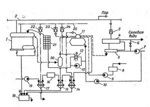
The fuel oil facility consists of a warehouse and a system for supplying fuel oil to the nozzles. Fuel oil arrives at the warehouse in road or rail tanks and is poured into receiving tank 3 (Fig. 57). To heat fuel oil in railway tanks, steam is used, which is directly introduced into the volume of fuel oil through a heating device. The heating temperature of fuel oil depends on its brand and is 30-40 0C. From the receiving tank, fuel oil is pumped into tanks 5 of the fuel storage facility, equipped with steam heating.
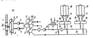
Fig.57. Principal circulation diagram of a fuel oil facility:
1 – railway tank; 2 – drain tray; 3 – receiving container; 4 – transfer pumps; 5 – fuel storage tanks; 6 – ventilation pipes of tanks; 7 – coarse filter; 10 – fuel pumps; 11- bypass line; 12- heater; 13 – fine filter; 14 – pressure line; 15 – return line; 16 – bypass valves; 17 – boiler nozzles; 18 - boilers
Fuel oil is supplied to nozzles 17 according to a circulation scheme, when more fuel oil is supplied to the boilers than is burned, and excess fuel oil is returned to the tanks. The constant movement of fuel oil through all fuel oil pipelines eliminates the solidification of fuel oil in temporarily inactive sections of fuel oil pipelines and ensures the rapid activation of backup boilers. In addition, the stream of hot fuel oil returning to the tank intensively heats the fuel oil and erodes bottom sediments in the tank.
On the way to the nozzles, the fuel oil is heated in heater 12 to the temperature required for high-quality atomization. Depending on the brand of fuel oil, this temperature reaches 80 – 120 0C. To avoid clogging of the nozzles, the fuel oil is cleaned of mechanical impurities in coarse 7 and fine 13 filters. The filters have the same design and differ from each other in the mesh size of the filter mesh.
To pump fuel oil and supply it to the nozzles, gear, rotary-gear and rock pumps are used. The pumps, together with fuel oil heaters and filters, are installed in a separate building called a fuel oil pump room.
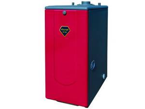
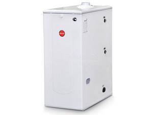
Manufacturers of liquid fuel boilers
Power: 0 - 13 kW, heated area: up to 130.0 m2, voltage: 220 V, combustion chamber: closed, number of circuits: double-circuit (heating and hot water), heat exchanger: separate (stainless steel/stainless steel) , overall dimensions (HxWxD): 754x320x520
Power: 0 - 16.8 kW, heated area: up to 130.0 m2, voltage: 220 V, combustion chamber: closed, number of circuits: dual-circuit (heating and hot water), heat exchanger: separate (stainless steel/stainless steel) , overall dimensions (HxWxD): 700x325x602
Power: 0 - 17 kW, heated area: up to 170.0 m2, voltage: 220 V, combustion chamber: closed, number of circuits: double-circuit (heating and hot water), heat exchanger: separate (stainless steel/stainless steel) , overall dimensions (HxWxD): 754x320x520
Power: 0 - 21 kW, heated area: up to 210.0 m2, voltage: 220 V, combustion chamber: closed, number of circuits: double-circuit (heating and hot water), heat exchanger: separate (stainless steel/stainless steel) , overall dimensions (HxWxD): 754x320x520
Power: 15 - 15 kW, heated area: up to 150.0 m2, voltage: 220 V, combustion chamber: closed, number of circuits: double-circuit (heating and hot water), heat exchanger: separate (stainless steel/stainless steel) , overall dimensions (HxWxD): 930x365x650

Power: 13 - 13 kW, heated area: up to 130.0 m2, voltage: 220 V, combustion chamber: closed, number of circuits: double-circuit (heating and hot water), heat exchanger: separate (stainless steel/stainless steel) , overall dimensions (HxWxD): 781x370x683
Power: 17 - 17 kW, heated area: up to 170.0 m2, voltage: 220 V, combustion chamber: closed, number of circuits: double-circuit (heating and hot water), heat exchanger: separate (stainless steel/stainless steel) , overall dimensions (HxWxD): 781x370x683
Power: 0 - 19.8 kW, heated area: up to 190.0 m2, voltage: 220 V, combustion chamber: closed, number of circuits: double-circuit (heating and hot water), heat exchanger: separate (stainless steel/stainless steel) , overall dimensions (HxWxD): 700x325x602
Power: 19.8 - 19.8 kW, heated area: up to 190.0 m2, voltage: 220 V, combustion chamber: closed, number of circuits: dual-circuit (heating and hot water), heat exchanger: separate (stainless steel/stainless steel) , overall dimensions (HxWxD): 920x360x640
Liquid fuel heating equipment is very popular in the domestic market, which is explained by its autonomous operation and modern automation.
The only drawback of these systems is the high cost of fuel and direct installation of equipment. Its installation will be fully justified in areas where there is no connection to the gas main. Sometimes, solid fuel equipment is a good alternative to liquid fuel boilers, but only if there is an energy source in close proximity.
Below we will consider the design and principle of operation of a liquid fuel boiler, as well as its installation.
Burners for oil boilers
The design features that are inherent in fuel oil boiler houses differ very little from the technological structure of boilers using liquid fuel.
This means that one boiler can be easily converted into another, just by changing the burner.
For boiler equipment that runs on fuel oil, the following types of burners are most often used:
- Dual fuel combination burners. They can burn one or two types of fuel - any jet flammable gas and naval fuel oil. The nozzles of such boilers are similar to the nozzle injection of high-pressure fuel pumps, but they are distinguished by a more complex and hermetically sealed design. Burners of this type were previously used only for use in the industrial industry (heating industrial workshops, burning waste, etc.), but now these installations are also used in everyday life. The only drawback of this type of burner is the following: the supply of gas and fuel oil requires a very long and difficult calibration in order to ensure a constant supply of the mixture and better combustion of the mixture in the combustion chamber of the boiler.
- Multi-fuel burners can only ignite liquid fuels, which include fuel oil or diesel.
- Mono-fuel burners are designed for only one type of fuel. Such devices are very easy to maintain, use and adjust. They are factory installed and are suitable for any burner application. Their price is significantly lower than multi-fuel or dual-fuel ones.
Types and operating modes of burners for liquid fuels
Some manufacturers sell liquid fuel heating boilers without burners. And that's why. The choice of burners for liquid fuel is quite large and there are many differences in types and operating modes.
Burner types
There are the following types of burners based on fuel:
- Mono fuel burners. They run on only one type of liquid fuel, usually diesel fuel. To switch to oils, you will have to change the burner nozzles.
- Bi fuel burners. They operate on several, often two, types of fuel. There are combinations: diesel-gas, diesel-wood, diesel-wood-coal, etc.
Types of burners by operating mode
We also pay attention to this:
Single-stage burner. Quite primitive, but because of this it is a reliable burner. Adjustment is made by simply turning the burner on/off. They are distinguished by maximum power output and maximum fuel consumption.
Multi-stage burner. This burner is configured to operate according to complex smooth on/off algorithms through intermediate power values. Such burners are expensive, but they save excellent diesel fuel. Typically, such burners are installed on powerful boilers from 40 kW.
About the fan (inflatable) burner of a liquid fuel boiler
The fan burner, also known as an inflatable burner, in an oil-fuel boiler is sold separately from the boiler itself. This allows you to assemble an oil-fuel boiler based on your individual needs. In addition, the liquid fuel burner can easily be changed to a gas burner and the liquid fuel boiler can be converted into a floor-standing gas boiler.
This is especially convenient if main gas has not yet been supplied to your house and a liquid fuel boiler is used as an intermediate option for heating the house before gas is supplied.
Topic 10. Preparation of liquid fuel for combustion.
Schematic diagram of the fuel oil economy of the boiler room. Preparation of fuel oil for combustion (heating temperature, use of additives).
Schematic diagram of the fuel oil economy of the boiler room.
When operating boiler plants, fuel oil is used as: the main and only type of fuel; reserve and emergency fuel, when the main fuel is gas; kindling fuel, when the main one is solid fuel burned in pulverized form.
Fuel oil is usually delivered by rail in tanks. Fuel oil is supplied to installations located a short distance from oil refineries through pipelines.
Fuel oil facilities for the delivery of fuel oil by rail consist of the following structures and devices: a drain rack and an intermediate tank; fuel oil pumping station with pumps for pumping fuel oil; fuel oil storage facilities with reinforced concrete or metal tanks; fuel oil pipeline systems between fuel oil tanks, fuel oil pumping and boiler plants; devices for heating fuel oil and wastewater treatment; installations for receiving, storing and introducing liquid additives into fuel oil; fire extinguishing systems.
The diagram of the fuel oil facility is shown in Fig. 10.1. From the railway tanks located on the overpass during the draining period, fuel oil flows through a portable drain tray into the drain chute and then through the outlet pipe into the receiving tank. From it, fuel oil is pumped into fuel oil storage tanks (as a rule, at least two tanks are installed). From it, as necessary, through coarse and fine filters and heaters, fuel oil is supplied by pumps to the burners of boiler units. Part of the heated fuel oil is sent through the recirculation line to the fuel oil storage facility to heat the fuel oil located there. To avoid freezing in the pipes, fuel oil continuously circulates in them - after passing along the boiler room, it returns to the fuel oil storage site. Steam lines are laid together with fuel oil lines and provided with general insulation.
Rice. 10.1. Fuel oil preparation scheme: 1 - tank; 2 — channel (tray); 3 — receiving tank; 4 - transfer pump from the receiving tank; 5 - main tank; 6, 10 — coarse and fine filters; 7, 11 — pumps of stages I and II; 8 — fuel oil heater; 9 – fuel oil pumping pump recirculation line; 12 - emergency valves; 13 — fuel oil pressure regulator; 14 - fuel oil consumption; 15 — boiler nozzles; 16 - recirculation fuel oil pipeline from the boiler room to the fuel oil pumping station
Fuel oil filters are designed for coarse and fine cleaning (the number of holes on the mesh is 5 or 40 per 1 cm2) of fuel oil from solid residues of oil fractions and mechanical impurities.
Preparing fuel oil for combustion.
To reduce the amount of bottom sediments during long-term storage, reduce the amount of soot formed during combustion and reduce contamination of the boiler heating surfaces, liquid organic or water-soluble mineral additives (0.5 - 2 kg/t), for example, the VNIINP series, are added to the fuel oil.
Heating of fuel oil is necessary to ensure its fine atomization under conditions of combustion intensification. M40 grade fuel oil should be heated to a temperature of 80 - 100 °C, M100 grade - 100 - 120 °C, M200 grade (the most highly paraffinic) - not lower than 135 °C.
To heat drain trays and heat fuel oil in receiving and main tanks to 70 °C, steam with a pressure of 0.6 - 1.2 MPa or hot water with a temperature of up to 150 °C is usually used.
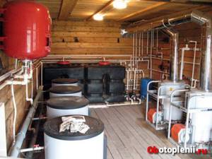
Description of the fuel oil boiler room
An oil boiler house is a well-organized heating installation equipped with high-quality equipment. The popularity of such complexes is explained, first of all, by the fairly low price of fuel.
The operating principle of an oil-fired boiler room is to use this type of fuel to heat the coolant to the required parameters. The proposed installations can be used as emergency or backup systems in the event of a failure in the operation of systems with the main type of fuel (for example, gas).
Fuel oil boiler houses (SPb) include fuel oil facilities. If this type of fuel is “spare”, then one tank is provided for its storage. If fuel oil is the main fuel, two containers are used. The amount of substance is designed for autonomous operation of the system for a certain time.
Oil-fired boiler installations (systems) operate on high-calorie fuel material. The most acceptable option for high-quality operation of the complex is the F 40 brand, but, as practice shows, the M 40, M 100 and M 200 brands are most often used.
Boiler houses using fuel oil in Russia (St. Petersburg) are offered by many companies. But it’s worth spending time and finding the most worthy one, since the correct design and competent assembly are the key to the future successful operation of the complex.
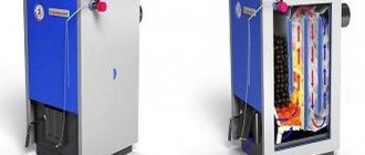
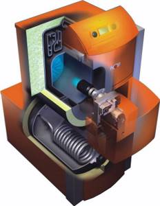
The operating principle of the liquid fuel installation and its design
The principle of operation of the boiler is in many ways similar to the operation of a gas floor-standing appliance. The main distinguishing feature is the difference in their designs.
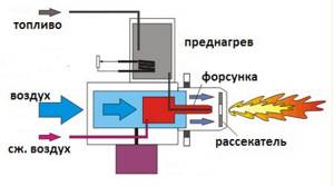
Homemade liquid fuel products have a fan burner for exhaust. Its function is to atomize fuel under high pressure and then feed it into the combustion chamber. The atomization process involves a nozzle that distributes the fuel into small droplets. The raw material itself is transformed into a fog-like form and mixed with the air flow forced by the fan.
The mixture of air and fuel entering the burner leads to the ignition process.
The main characteristic of the effective operation of equipment is its power. In order to understand what power you need a boiler to create a comfortable microclimate, you should carry out a series of thermal calculations.
Factors that are taken into account when calculating the power of the installation:
- area of the heated room;
- number of doors and windows in the room;
- walls and their thickness;
- floor thickness;
- presence of thermal insulation.
In addition, the number of people living also matters in calculating the required power. It is better to entrust such calculations to professionals from the company where you ordered the equipment.
At home, you can only determine the approximate value of the parameter. On average, for a house whose ceiling height does not exceed 3 m, you should purchase a device in accordance with 1 kW of power for every 10 m 2 of area.
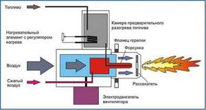
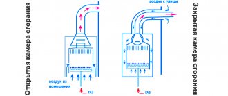
Gas burner operating diagram
Fuel storage tank
Now comes the fun part. An oil-fuel boiler requires a container for storing fuel, and I listed this as a disadvantage a little higher.
The calculations shown above indicate that a capacity of several tons is needed. There is no need to invent anything here and it is better to buy a ready-made container with all the built-in equipment: a float, a vapor outlet, a drain valve, a fuel intake kit, a pipeline for discharging fuel to the burner, etc.
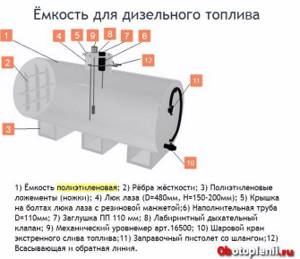
Material for containers is steel, polyethylene, fiberglass.
To install the tank, site preparation, excavation, concreting and a lot of special work will be required. You need to understand this and most likely, you will have to hire specialists.
Complete set of fuel oil boiler room
Since these complexes are liquid fuel, the production of an oil boiler depends on various factors:
- Required power.
- Fuel oil stock quantities.
- Options for fuel delivery and storage.
High-quality construction of fuel oil boiler houses is based on accurate calculations and careful selection of appropriate equipment:
- Building.
- Boilers.
- Pump group.
- Expansion membrane tank.
- Fuel supply, unloading and storage system.
- Fuel purification filters.
- Chimney.
- Control system.
- Alarm and other components.
After weighing all the pros and cons, many customers choose fuel oil boiler houses, the price of which varies within reasonable limits. The cost of the system largely depends on the required power and size.
When creating a project for a boiler house using fuel oil, a diagram, drawing, technological map and other calculations are required. Employees are always ready to: correctly calculate the required amount of fuel, the total power of the installation, take into account the availability and need to order the appropriate components, calculate the total amount of investment, etc.
It is best to find out the cost and buy an oil boiler from a specialized company that has:
- Considerable experience in this field.
- All permits.
- Lots of good reviews from established clients.
How much fuel is needed for the season?
One of the most important questions to decide is how much fuel you will need for the season. Let's count.
Simplified, it is considered that:
- 1 liter of diesel fuel allows you to heat an area of up to 100 meters within an hour.
- The boiler consumption is calculated as the power of the burner used multiplied by 0.1.
- And as always, 1 kW of the boiler will heat 10 square meters. meters of house.
Let's make an approximate calculation, from the word example.
A logical question arises: Why, compared to the calculation using the passport (above), did this calculation above give completely different results and where is the correct calculation?
I answer: The error is 72 liters per day. Not one diesel boiler will work 24 hours a day.
As I said, diesel boilers have very serious automation. The boiler will be turned off for 2/3 days, not turned on. Therefore, the calculation should include not 24 hours of work, but 8 hours. That is, the fuel needed for the season is not 10,449 liters, but 3,483 liters.
In addition, modern boilers have technological tricks that also reduce fuel consumption, for example, multi-stage burners, burners with turbo circulation.
One more thing. The calculation given at the beginning of the article is based on the passport data of the boilers, which were compiled taking into account the quality of the fuel in the country of origin. Also, the boiler consumption indicated in the passport is slightly underestimated, since it implies ideal insulation of the house, the outside temperature is minus 10-15˚C and is given for an already heated house (heat maintenance mode).
Therefore, the correct calculation of fuel consumption for the heating season will be somewhere in the middle between 1957.5 liters according to the passport and 3483 liras according to the calculation. We remember that I considered the house to be 300 meters away.
Lighting up the stove
When lighting the stove during testing, it is necessary to inspect the chimney and lower container each time for the presence of water in them. If it is not there, then you can add oil (usually about 2-3 liters). Ignition must be carried out with a lit wick, which is inserted into the container through the hole. The oil usually reaches operating temperature in no longer than 5 minutes, but there are cases when the temperature is reached faster.
To speed up this process, you can add about 100 ml of kerosene to the used oil. The hole in the lower container should be left open literally a couple of centimeters, and later, by pushing the damper in or out, you can regulate the combustion process.
Boiler house building
2.1.1. The category of the boiler room in terms of explosion and fire hazard is determined in accordance with the “List of premises and buildings of energy facilities of the USSR Ministry of Energy indicating the categories of explosion and fire hazard”.
2.1.2. Boiler rooms must have natural or forced ventilation and lighting that meet the requirements of the “Sanitary Standards for the Design of Industrial Enterprises.”
2.1.3. (Deleted. Change No. 2)
2.1.4. The walls inside production premises must be smooth and painted with waterproof paint in light colors.
2.1.5. The floor of the boiler room at the service level and below must have an easily washable coating.
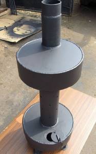
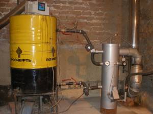
Operating principle of the boiler
The boiler consists of two metal containers connected by a pipe. A chimney is installed in the upper part, the length of which must be at least a meter. The lower container is intended for pouring waste, where the top layer of oil is heated and turns into oil vapor. Rising, the steam exits into a perforated pipe, mixes with air, reaches the upper container and burns. Combustion products exit through the chimney; thus, the boiler heats the room but does not emit toxic waste.
Waste oil heating boilers
A boiler without a water circuit can easily heat a garage of about 40 square meters. m. As for products with a water circuit, they allow you to maintain a comfortable temperature in fairly large rooms even in severe frosts. Moreover, fuel consumption ranges from 0.5 to 1 liter per hour, which makes it possible to significantly save on energy resources.
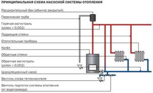
Pump heating system
Pump heating system. Circulation pump
The exhaust boiler can be made single-circuit or double-circuit, depending on the needs of the owner. If you use coolant only for heating, you need a single-circuit boiler. The second option allows you to heat the room and obtain hot water for domestic purposes; for this purpose, there is a built-in heat exchanger in the upper tank.
Video - Option of a furnace being tested before connecting the water jacket
The operating principle of such a boiler is also quite simple: from the supply tank, the pump delivers the waste to the evaporation chamber, where it is heated and turned into steam. Steam rises into the combustion chamber, mixes with air and heats the water in the circuit. Hot water enters the pipes and radiators, heats the room and returns back to the boiler.
As practice shows, a waste oil boiler is an effective heating device, and also affordable
As practice shows, a waste oil boiler is an effective heating device, and also affordable
As practice shows, a waste oil boiler is an effective heating device, and also affordable
Oil boilers in operation
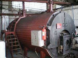
The operation of a boiler house built using a boiler using fuel oil: the fuel enters the receiving chamber, then, bypassing the storage, it reaches the nozzles through process lines through filters to remove coarse impurities.
Fuel oil heating chambers (preliminary preparation) are installed in front of the nozzle. Next, fuel oil is mixed with condensate to prepare an emulsion.
The finished emulsion is fed through a production line to the burner, where the jet under pressure is ignited using a piezoelectrode.
Conclusions on consumption calculation 1
Based on the given fuel consumption data, you can estimate the cost of heating for the season.
- We take the heating season to be 6 months, or 180 days.
- For a house of 300 meters, a 30 kW boiler is required (1 kW per 10 meters).
- We choose a boiler from the list above at 34.9 kW, which consumes an average of 12 liters of diesel fuel per day. (10.0-14.5 l).
- The maximum fuel consumption for 180 days will be 180×14.5=2610 liters.
- We understand that no one will heat at maximum the whole season. We assume that for 90 days of the heating season the boiler operates at 100%, and for 90 days at 50%.
- We get: 90×14.5+90×14.5/2=1305+652.5=1957.5 liters.
- Diesel fuel 1957.5 liters costs (retail 38 rubles) 74385 rubles (1240 rubles per month).
In the article “Simplified calculation of the heating system,” I showed the calculation based on the power of the heating boiler. Below there will be another calculation that will show different results.