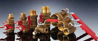
Types of valves
As mentioned earlier, the distribution of flows in the valve occurs using an actuator, of which there are several types:
- thermostatic (thermostat). This is the most popular actuator, which works due to the thermal expansion of the sensing element, after which pressure is applied to the valve stem, and the hot and cold flows are mixed;
- electric is also a fairly common type of actuator, installed in a three-way valve. It works by sending signals from the control unit;
- thermostatic head, where the valve is controlled by pressing the rod of its drive. It responds to the temperature detected by it or an external sensor. Often such a drive is used to create underfloor heating systems.
There are also automatic and mechanical models:
- in automatic valves the membrane moves on its own, depending on the temperature;
- in mechanical ones, the separator is installed manually, which requires a thermometer on each incoming pipe to monitor temperature indicators.
Valve device
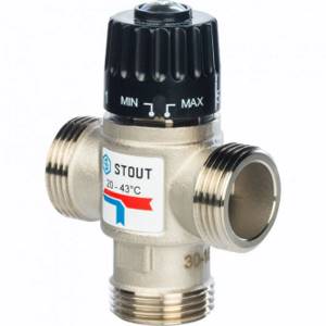
A similar unit is installed on all models of heaters. Its design is standardized, so only the overall dimensions can differ. So a three-way valve for an Ariston, Arderia, Navien, boiler and any other model will look the same in appearance.
As for the technical characteristics, this parameter must be clarified in the data sheet. You should not try to attach a spare part to the boiler that does not fit in size, since it will still not function normally, but trouble in the form of a serious breakdown may well occur due to such actions. And in the end, the desire to save will lead to additional costs.
The three-way valve for solid fuel and gas boilers is also no different in design. The type of fuel used to obtain thermal energy does not in any way affect the circulation characteristics of the coolant. The fact is that the valve does not contact the combustion chamber in any way, so it does not need to be adjusted to the type of heating system.
As for the coolant, in 100% of cases Russian citizens use ordinary water at home. This is due to its availability and the absence of any problems with operation. There is no point in inventing anything if the heating already works well and has many years of successful experience in use.
These parts are made of bronze or stainless steel. Polymer analogues are still not widespread, although in the future one can predict an increase in their number if they perform well in operation.
The design of a three-way valve for a gas boiler is very simple. It is T-shaped with two inlets and one outlet. Inside there is a special membrane that regulates the flows coming from different sources so that the optimal temperature is achieved.
There are automatic and mechanical options.
- In automatic modes, the membrane moves automatically, depending on the temperature of the coolant.
- In mechanical units, the position of the separator is set manually by a person, so it is necessary to additionally install thermometers on each incoming pipe in order to be able to monitor the temperature value.
So the operating principle of a three-way boiler valve is based on the well-known laws of physics.
The principle of operation of a double-circuit gas boiler
Now we will begin to analyze the principle of operation of a gas double-circuit boiler. We have found out the purpose of individual components and modules, now this knowledge will help us understand how all this equipment works. We will consider the principle of operation in two modes:
- In heating mode;
- In hot water generation mode.
In heating mode, the boiler provides your home with heat.
Let us immediately note the fact that operation in two modes at once is impossible - for this purpose, double-circuit boilers are equipped with a three-way valve that directs part of the coolant to the DHW circuit. Let's look at the principle of operation when heating, and then find out how the equipment works in hot water supply mode.
In heating mode, a double-circuit boiler operates in the same way as a regular flow-through heater. When first turned on, the burner works for quite a long time, raising the temperature in the heating circuit to the set point. As soon as the required temperature is reached, the gas supply will be turned off. If an air temperature sensor is installed in the house, the automation will take its readings into account.
The operation of the gas burner in double-circuit boilers can also be affected by weather-dependent automation that controls the temperature of the outside air.
The heat from the operating burner heats the coolant, which is driven through the heating system in forced mode. The three-way valve is positioned to ensure normal water flow through the main heat exchanger. Combustion products are removed in two ways - independently or using a special fan located in the upper part of the double-circuit boiler. The DHW system is in a switched off state.
Operation in hot water mode
As for the hot water supply circuit, it starts the moment we turn the handle of the water tap. The resulting water flow triggers the three-way valve, which turns off the heating system. At the same time, the gas burner is ignited (if it was turned off at that time). After a few seconds, hot water starts flowing from the tap.
When switching to hot water supply mode, the heating circuit is completely turned off.
Let's look at the principle of operation of the DHW circuit. As we have already said, turning it on turns off the heating operation - only one thing can work here, either the hot water supply or the heating system. A three-way valve controls it all.
It directs part of the hot coolant to the secondary heat exchanger - note that there is no flame on the secondary. Under the influence of the coolant, the heat exchanger begins to heat the water flowing through it
The scheme is somewhat complicated, since it involves a small circle of coolant circulation. This operating principle cannot be called the most optimal, but double-circuit gas boilers with separate heat exchangers can boast of normal maintainability. What are the features of boilers with combined heat exchangers?
- Simpler design;
- There is a high probability of scale formation;
- Higher efficiency of DHW.
As we see, the disadvantages are closely intertwined with the advantages, but separate heat exchangers are more valuable. The design is somewhat more complicated, but there is no scale here
Please note that when the DHW is operating, the flow of coolant through the heating circuit stops. That is, its long-term operation can disrupt the thermal balance in the premises
As soon as we close the tap, the three-way valve is activated, and the double-circuit boiler goes into standby mode (or the heating of the slightly cooled coolant immediately starts). The equipment will remain in this mode until we open the tap again. The productivity of some models reaches up to 15-17 l/min, which depends on the power of the boilers used.
Error code F1 (07)
Unsatisfactory traction. In order to ensure stable and reliable operation of the device, it is necessary to create draft to remove exhaust gases so that they do not penetrate into the room. This is monitored automatically, and when certain problems occur, the traction sensor will work and the device will stop working. The main reasons that may result in a lack of draft are: insufficient size of the smoke exhaust duct, inaccuracy during installation, contamination with dirt, ice on the walls. A decrease in the diameter of the outlet channel may cause a weakening of traction. Exceeding the maximum length of the chimney pipe. It is necessary to carefully study the instructions for using the gas unit and comply with the relevant requirements. A horizontal section of the chimney pipe that is too long may cause a lack of necessary draft. Failure of the pneumatic relay-traction sensor - When a vacuum is created in the inlet tube, a soft click will be heard. Poor contact of the control board with the pneumatic traction relay, condensation is present, as well as incorrect connection of the tubes to the pneumatic relay. Fan problems – The fan impeller is clogged. There is not enough lubricant on the fan shaft, which means it has low speed. Poor contact between control board and fan. Error code F4 (14)
Problems with determining the temperature by the DHW sensor.
This circumstance indicates a malfunction of the temperature sensor in the hot water supply circuit or the operating temperature has increased significantly. Possible sources of this problem: the DHW temperature sensor is broken. Lack of contact between the hot water temperature sensor and the electronic board. The electronic board is faulty. When the DHW temperature sensor is working and is connected stably to the control board, but the unit generates an error, then it seems that the electronic board has failed. Error E1 (01)
It shows that there is no ignition.
The flame ionization sensor signals a malfunction of the device. Such a component detects the presence of a flame and blocks the operating cycle of the Elsotherm boiler during low combustion of the main burner or when the gas supply is interrupted. Blocking occurs after 3 unsuccessful starts. To resume the workflow, press and hold the Reset button. Problem with the gas valve – The action of the gas valve is controlled by the electronics board. This component is checked by measuring resistance and voltage. If the readings are found to be outside of standard specifications, the valve should be replaced. There is no gas supply to the boiler - There is a valve in the gas distribution system that closes the gas supply. Therefore, a problem when starting the boiler may occur due to a closed valve. Poor contact or no signal from the flame control sensor. The control board is faulty - If ignition is carried out normally, but the unit goes out immediately in any case, then it can be assumed that the electronic board cannot see the flame. In this case, it should be diagnosed. Error code E3 (F5, 04)
Elsotherm boiler overheating.
The operation of the device is blocked. The overheating safety thermostat has turned on - The overheating thermostat, as well as the temperature sensor, are usually located on the outlet pipe of the primary heat exchanger. An important function of the thermostat is to protect the device from elevated temperatures. The malfunction appears due to problems with the thermostat, temperature sensor, and also when the main circulation circuit is difficult to operate. The temperature sensor is faulty - The control board receives an incorrect signal or there is a loss of contact between the sensor and the electronic board. The overheating thermostat is faulty - If the thermostat is suitable for operation, but real overheating of the liquid is detected, then there seems to be a problem with the circulation of the coolant in the heating circuit. The main heat exchanger or the filter element of the main circuit is clogged (low circulation level means increased heating of the liquid). The circulation pump has broken down or there is an air blockage in the heating system. Error F2 (95)
Indicates low pressure in the system.
The main factors causing this malfunction are: a decrease in water pressure in the heating circuit. The contact between the control board and the minimum pressure switch is broken. The pressure switch is faulty. You must first check the pressure gauge values. As a rule, the failure can be corrected by using a make-up tap, which is designed to fill the heating circuit with water. When the accident reappears, there is most likely a coolant leak. The hydraulic pump, primary heat exchanger, excess pressure relief valve, worn seal elements, make-up valve and other components may be leaking. Leaks can be detected during an external inspection of hydraulic units and components. Error E2 (02)
Ignition failure.
This occurs when the ignition mechanism does not work or the burner flame goes out. It is necessary to inspect the connections between the ignition unit and the flame sensor, as well as between the control board and the gas valve. The main reason for the burner flame to come off is weak draft. Error F3 (24)
The heating circuit temperature sensor is not working correctly. This circumstance means that the temperature sensor in the heating system is faulty or the required temperature has risen. The temperature sensor circuit in the heating circuit is damaged - This malfunction can occur when there is no contact between the temperature sensor and the electronic board, or the temperature is below normal. Within 5 seconds after detecting a fault, the Elsoterm boiler will resume normal operation if the fault occurred spontaneously. You need to make sure that there is no moisture on the temperature sensor connector and the electronic board connector. If there is no moisture, you need to change the sensor. Short circuit of the temperature sensor in the heating circuit - This failure occurs due to a short circuit of the temperature sensor circuit or the coolant temperature is higher than the nominal one. The first step is to measure the resistance of the temperature sensor. If the resistance parameters differ from the nominal ones, it is recommended to replace the temperature sensor. When installing a new sensor does not help, repair the board. A year ago we connected an Elsotherm gas boiler to the system. Over the last month, ignition error 01 appears almost regularly. After rebooting with the reset key, the unit periodically starts up without problems, but this does not happen often. The other day I removed the air plug and it worked better. What could be wrong?
When a traction error starts to appear, you need to open the protection covers. This will promote air flow from the room. After this, inspect the chimney for the presence of ice and, if necessary, clean it. If the failure is associated with flame separation, you need to find out whether gas is being supplied to the room. Often the boiler displays error code F3. Please tell me what it means? This code may indicate problems with the heating temperature sensor. Looks like it needs to be changed.
For what reason does the Elsoterm gas boiler not turn on? In this case, error E3 often appears. What should be done? This malfunction may appear due to some problems in the thermostat, temperature sensor, and also due to malfunctions in the main circulation circuit. It can be assumed that the heat exchanger has overheated. If the temperature sensor and thermostat are working properly, then the problem is in the control board. It will need to be changed. Why does the unit not start and error 95 is displayed? The pressure is maintained normally, no leaks are visible. I turn it off from the mains, but the problem remains. Help, how to fix it?
This situation usually occurs when the water pressure in the heating circuit is low. In this case, it is necessary to check the pressure switch sensor. It must be faulty. The problem with the unit is the following: the hot water supply is turned on at 45 degrees. If you open a hot water tap, the gas burner starts to burn and quickly goes out. This cycle occurs all the time. Either warm water or cold water flows from the mixer. Sometimes error code 04 is displayed. What is the problem? This circumstance indicates boiling water in the DHW circuit. The heat exchanger is probably clogged with debris, or the thermostat is not set correctly. I have this problem. When igniting, the unit displays error E2 (02). When we reboot, it turns on normally, but as soon as the burner ignites, you can hear several clicks, and the error is shown again. I replaced the ionization electrode, washed the flow sensor, removed the ground from the plug, but there was no result. What's happened? This malfunction can occur for several reasons. Broken ignition electrode. Incorrect gas supply. The control board is damaged.
The unit has stopped working autonomously and is displaying code 95. What should I do? There is no liquid in the device or the pressure switch sensor is broken. First fill the system with coolant. The unit turns off with error code F1 displayed. I cleaned it and blew it out - it doesn't help for long. What's happened? This code indicates unsatisfactory draft, and it is recommended to check the chimney system. Presumably, the membrane may stick. In another case, it is necessary to contact specialists for a detailed inspection of the boiler and further inspection. At home we use an Elsotherm boiler. An error with code F3 began to appear. The device itself does the work; the water temperature level is manually adjusted. When installing it, it seems that overheating occurred, since the automatic temperature mode was turned on. There is no outdoor air temperature sensor. What is the reason and how to eliminate it? We assume that the DHW temperature sensor is faulty. In some cases, the electronic board is damaged. The device is in operation for about two to three minutes, after which the gas burner stops working and error 07 is displayed. It burns for no more than a minute, the burner turns on again, and the unit works well for another five to six minutes, and so on in a circle. This failure, judging by the instructions, means that the draft sensor has tripped, although the chimney channel is clean and exhaust gases are discharged normally. I just can’t figure out what is causing the problem? In your case, the probable reasons for the lack of traction may be: a malfunction of the traction sensor pneumatic relay. There is no contact between the control board and the pneumatic traction sensor. There is condensation, as well as incorrect fastening of the tubes with the air relay sensor. Damage to fan components. It looks like he can't develop the necessary speed.
Elsoterm
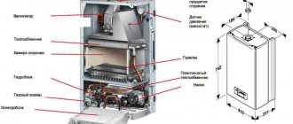
boiler The wall-mounted double-circuit gas boiler Elsotherm with forced circulation of coolant with a closed combustion chamber is used for heating residential and safe industrial buildings, as well as for hot water supply (DHW) for sanitary purposes. The model range includes the following modifications: b15fi, b19fi, b23fi, b35fi. The boiler is equipped with a safety system that shuts off the gas supply to the burner if there is insufficient or no draft in the chimney. The control unit (board) is electronic. The fan control unit continuously regulates and monitors the fan pulley speed. When the board receives an electrical signal different from the standard one from the fan control unit, due to a violation of normal draft or damage to the speed control mechanism, the board immediately stops the operation of the unit, cutting off the gas supply.
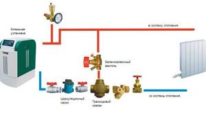
Heating circuit functions – There is no water flow in the DHW circuit. A three-way valve is included for the movement of coolant along the heating circuit with the following order of passage of nodes: primary heat exchanger; expansion tank; circulation pump; three-way valve; radiators; primary heat exchanger, etc. Functions of the DHW circuit – If there is a water flow in the DHW circuit, heat is collected in a coil integrated in the expansion tank. The 3-valve is turned on for the movement of the coolant along the hot water preparation circuit with the following order of passage of the nodes: primary heat exchanger; expansion tank; circulation pump; three-way valve; main heat exchanger, etc. Errors and malfunctions of Elsoterm boilers
Error 01
– No ignition.
No gas supply - Check that the gas tap is open and restart the boiler. The cylinders have run out of liquefied gas - Replace the cylinders with liquefied gas. Incorrect gas pressure adjustment – Check the gas pressure upstream of the unit. Adjust the minimum and maximum gas pressure at the gas unit. Ignition malfunction - inspect the electrical wiring, ignition transformer and control unit. Fault in the gas unit – Check the electrical wiring, gas unit or control board. Error 02
– No ignition.
Incorrect operation of the flame presence photosensor - Close the unit lid, clean the sensor window or electrical wiring. Replace the photosensor or control unit. Error 03
– 5-fold sequential flame extinction within one minute.
Insufficient gas pressure – Check the diameter of the gas supply pipe. Adjust the gas unit to the required minimum pressure (control unit). The chimney is blocked – You need to check the blockage of the chimney. Incorrect operation of the photosensor - Carry out work on error code 02. Error 04
- Problem with the coolant temperature control.
Damage or incorrect connection of temperature sensors – Check the connection of temperature sensors. Replace sensors, electrical wiring, control board. Error 05
– The contact in the overheating sensor circuit is damaged, the sensor is not working correctly, or the seismicity sensor is not working. Damage or incorrect connection of temperature sensors. High vibration or seismic activity – Check temperature sensor connections. Replace sensors, power supply wires, electronic board. Check and/or replace the seismicity sensor.
Error 06
– The fan speed is not detected or the fan speed sensor does not work.
Fan malfunction, chimney blocked by foreign objects, control unit malfunction - Restart the boiler. Check the condition of the chimney. Check the control voltage on the fan. Replace the fan and power supply wires. Error 07
– The fan speed is different from normal.
The chimney is not installed correctly. The chimney is faulty. Faulty fan or control unit. Complete or partial blocking of the chimney by foreign objects, water or condensate. The external opening of the chimney is blocked by ice – Restart the boiler. Check the condition of the chimney and the control voltage on the fan. Check the correct position of the chimney. Check the tightness of all connections, the correct position of the chimney and the need to install a condensate trap. Carefully scrape off the ice. Replace the fan and power supply wires. Error 08
– There is no electrical connection with the room thermostat or there is no thermostat signal for 10 minutes.
The cable is damaged. The cable is too long. Electromagnetic interference – Check the cable, its cable length, or install a shielded cable. Error 14
– Problem with temperature control at the DHW outlet.
Defect or incorrect connection of temperature sensors – Check the connection of temperature sensors. Replace sensors, electrical wiring, control board. Error 24
– Incorrect operation of the residual heat sensor of the coolant.
Damage or incorrect connection of temperature sensors – Check the connection of temperature sensors. Replace sensors, electrical wiring or electronic board. Error 34
– Contact failure in the temperature sensor circuit at the DHW input or its incorrect operation. Faulty or incorrect connection of temperature sensors – Check the connection of temperature sensors. Replace sensors and electrical wiring.
Error 91, 92
– Low coolant level or communication with the coolant sensor is broken.
Evaporation or leakage of coolant. Malfunction of the low level sensor or electronic board – Make sure there are no leaks in the boiler and heating system. Refill the system through the make-up tap. Check the low coolant level sensor and power supply wires. Error 95
– The amount of coolant in the heating system is insufficient.
Pressure drop when moving to a warmer season or due to a leak in the boiler or heating system - If water leaks from the boiler, stop the boiler and notify a specialized company. Check the heating system for leaks and, if there are none, open the heating circuit feed tap and bring the water pressure in the heating system to the operating range, having first ensured the flow of cold water to the boiler. Error 96
– The boiler overheating safety system is activated.
Stopping the circulation pump - Open the hot water tap and wait until cold water comes out of it, then restart the boiler. In case of repeated boiler shutdowns, contact a service organization. Error 97
- a gas leak or carbon monoxide accumulation has been detected in the room.
Leak in the gas unit or gas connections. The chimney is faulty or incorrectly installed. Gas leak sensor is faulty – If you smell gas, eliminate the leak. Check the chimney for serviceability. Check the gas leak sensor and power supply wires. Malfunctions and repairs
The Elsoterm gas boiler has a timer set: 30 min. work and 1 hour of rest. But it does something incomprehensible: I set the battery temperature to 50 degrees, the unit runs for 15-20 minutes, but rests for exactly 1 hour. The batteries cool down and the temperature in the house is not constant. It’s cold, and the pipe freezes in cold weather. Set a timer. I have a timer for 3 minutes of rest after reaching the set temperature. The system is equipped with an Elsoterm gas boiler, which worked for 2 years without problems. Now it's starting to fail. Ignition occurs with a bang and often results in an ignition error. There is a spark, gas flows, there is no ignition, after a few minutes there is a bang and ignition, and sometimes it does not have time to ignite and goes into error. The gas pressure to the injector is normal. There are suspicions about the fan adjustment. Maybe someone has encountered such a problem? Tell me how to regulate the turbine speed on this model? We recommend that you contact a specialized organization. A full inspection is needed. On the Elsotherm b15fi wall-mounted boiler, the coolant enters the water supply circuit. The device has not been used before, but has been stored for a long time. We managed to start it up, but for heating, without hot water supply. It heats up, but periodically gives error 95 and cannot ignite.
Error 95 means that the coolant level in the heating system is insufficient. Possible reasons could be the secondary heat exchanger, or the make-up valve is not closed. Boiler model b19fi. When turned on, error 95 appears. The day before, I drained the water from it and raised the pressure to 1 atm. in the expansion tank, then raised it in the system to 1.5 atm. I worked for a night and half a day, and again the error occurred. Maybe I'm doing something wrong? I filled 1 atm. into the expansion tank with the drain valve open and the top drain nipple open. Then he closed the tap, and after raising the pressure in the system, tightened the upper nipple. Open the auto air valve. The unit is airy, so air gets into the sensor, and it gives an error. What is the gap between the ignition electrodes of the Elsotherm wall-mounted gas boiler? Ignition electrodes are consumables and we recommend replacement. Gas boiler Elsotherm b15fi in operation. The circulation pump has stopped working, the armature does not rotate, it hums. I took it apart and thought it might be clogged and jammed, but everything was clean. I collected it, but nothing changed. It is necessary to check the starting capacitor, also inspect the winding, check, connect without load (separate from the unit), if there is a smell, the engine needs to be repaired or replaced. The Elsotherm boiler displays error 96. Is the malfunction possible due to a clogged coolant filter? And what is the procedure for cleaning the filter? The control board, boiler filter, circulation pump, three-way valve may be faulty, or the internal or external heating circuit is clogged with scale. What could be the possible reasons for error codes 02 and 07? In this case, ignition occurs, but after 10 seconds it goes out.
Error code 02 – flame control sensor does not work, error 07 – incorrect selection of fan speed. Usually in such cases adjustment and maintenance are required. Elsotherm b23fi boiler installed. The first year when the heating was operating, the pressure in the circuit was 2-2.5 atm. Now after ignition it begins to increase, sometimes reaching 3.7. The instructions indicate a maximum pressure of 2.5. Tell me, what is the reason and is this pressure dangerous? Check the operation of the expansion tank; we recommend installing an additional expansion tank on the heating system. Elsotherm b35fi boiler in operation. It works after starting for 10-15 seconds and goes out, restarts, works the same again, sometimes it goes into error 03. Previously, during operation, there was a strong noise in the area of the burner or expansion tank. Error code 03 – flame break. Most likely, correct configuration is needed. We recommend calling a service technician. Maintenance and service of Elsoterm boilers
Cleaning the burner and manifold
1) To clean the burner, the following operations must be performed.
2) Dismantle the gas manifold and burner and wipe with a damp cloth to remove dust; 3) Use a brush to remove carbon deposits from the outer surfaces of the burner and manifold and from the internal channels of the burner sections; 4) If necessary, rinse the burner and collector with a soda solution and clean the internal cavities of the burner sections with a brush. Rinse them thoroughly with running water, dry them and install them in place. Keeping the burner constantly clean will eliminate soot contamination from the heat exchanger and increase its service life. Cleaning the primary heat exchanger
If the heat exchanger is dirty, it is necessary to clean its outer surface when soot has formed on it, and the inner surface of the heat exchanger pipes when scale has formed in them.
Removing contamination from the outside - Dismantle the heat exchanger and immerse it in a solution of soda or other detergent; – Keep it in the solution for 10-15 minutes and clean the upper and lower surfaces with a brush. Rinse with a strong stream of water; – If necessary, repeat the entire process. Removing scale from the inner surface of the pipeline 1. Remove the heat exchanger and place it in a container; 2. Prepare a 10% solution of citric acid (100 g of powdered citric acid per 1 liter of warm water) or use a special product for cleaning copper heat exchangers in accordance with its instructions; 3. Pour the prepared solution into the heat exchanger pipeline. Leave the solution for the time necessary to dissolve the scale, then drain and rinse the pipeline thoroughly with water. If necessary, repeat the entire process. 4. Install the main heat exchanger in place. Cleaning the inner surface of the pipes of the integrated DHW circuit in the expansion tank
1. Dismantle the expansion tank and place it in a container;
2. Prepare a 10% solution of citric acid (100 g of powdered citric acid per 1 liter of warm water) or use a special product for cleaning steel pipes in accordance with its instructions; 3. Pour the prepared solution into the pipeline of the integrated DHW circuit. Leave the solution for the time necessary to dissolve the scale, then drain the solution and rinse the pipeline thoroughly with water. If necessary, repeat the entire process. 4. Install the expansion tank with an integrated DHW circuit into place. Checking the air pressure in the expansion tank
1) Check the air pressure in the expansion tank after closing the shut-off valves of the heating system and draining the water from the boiler.
2) Remove the cap from the air pumping valve located in the middle of the expansion tank; 3) Through the valve, measure the air pressure. The air pressure should be 0.09±0.02 MPa; 4) If the air pressure in the expansion tank is below the permissible level, it is necessary to increase it to the required value using a pump (or other safe method); 5) If damage to the internal membrane is detected, replace the expansion tank (air pressure is not restored or water comes out of the air pump valve). The expansion tank needs to be replaced. Checking the nominal supply pressure of natural or liquefied gas in front of the boiler
1. The gas pressure is checked with the unit running. It is recommended to use a U-shaped pressure gauge as a measuring device. 2. To measure gas pressure, close the gas valve in front of it; 3. Connect the pressure gauge to the gas pressure measuring pipe, having previously unscrewed the screw with the seal; 4. Open the gas tap and turn on the unit in the maximum gas flow mode (for example, in the mode of producing the maximum amount of hot water in the DHW circuit); 5. Determine the instrument readings and check for compliance with the data in the table with technical characteristics; 6. After the measurement, turn off the device and close the gas valve; 7. Disconnect the pressure gauge; 8. Screw the screw with the seal onto the gas pressure measuring pipe; 9. Check the installation location of the screw for leaks using the soaping method. The appearance of bubbles means a gas leak. Gas leakage is not allowed.
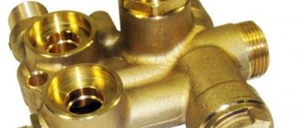
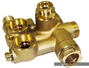
Thermal mixing valve design and operating principle
Like most parts and structural elements of a solid fuel boiler, the three-pass or also has a simple and understandable design. It includes:
- main body;
- spring-loaded rod;
- two dampers, disc type;
- thermostatic element (head with fixed positions).
The diagram shows in detail the mechanism in cross-section, where and how its main elements are located.
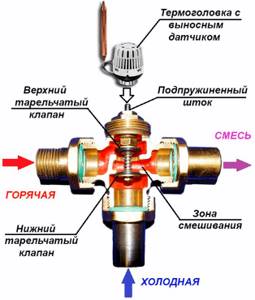
Looking at the design of the device, it is not difficult to understand the principle of operation. Let's take a closer look at the processes taking place.
During normal operation of the heating system, the main dampers, located linearly, are in the open position. Insufficiently hot water flows freely from the boiler into the heating circuit.
The thermostatic head, equipped with a temperature-sensitive liquid sensor, is in the standard position. If an emergency situation occurs, for example: coolant begins to flow into the system from the boiler side, the temperature of which exceeds the specified parameters. The temperature control sensor is activated, driving the rod. The operating mechanism closes the main, direct-flow passage, while simultaneously opening a passage from the side through which cold water flows. As a result of mixing water of different temperatures, the temperature equalizes to the established norm. The coolant, already at normal temperature, leaves the device through the pipe into the heating system. The adjustment of the thermostatic head of the device is determined by the degree to which the bellows with the expanding liquid is pressed onto the rod. Accordingly, determines the sensitivity of the device.
The moment the device operates is determined by adjusting the head, set to a certain temperature.
If the water continues to heat up as a result of the actions taken, the device shuts off the main incoming flow, allowing access to cold water from the third pipe. The rod in this case is in the lowest position. Water from the third pipe is already mixed into the main flow. When the temperature of the coolant changes downward, the rod, under the action of the sensor, reduces the pressure, opening access to hot water.
In order to achieve proper operation of the entire mechanism, it is necessary to strictly comply with the requirements for its installation. can be installed in a right-handed or left-handed version, both on the return and on the supply circuit. During operation, the device requires absolutely no maintenance.
Advantages and disadvantages of thermostatic three-way valves
The undoubted advantages of using three-way thermostatic valves:
- Ease of influence on the temperature of the working environment.
- Practicality and energy efficiency of the heating system.
- Easy installation and maintenance.
- Long service life (depending on the material from which it is made).
Among the disadvantages, I would note the relatively high cost and the need for a filter in the heating circuit to ensure a high degree of cleanliness of the coolant.
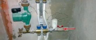
Valve connection
connection diagram
When connecting a three-way valve with your own hands, it is necessary to take into account the direction of the coolant. It is usually indicated by an arrow directly on the product itself.
It is worth noting that such a valve can be installed in a heating system in both a vertical and horizontal position, and the installation location does not play a special role.
However, when connecting, it is important to follow a number of certain rules so that in the future the entire system functions normally:
- All work is done very carefully so that not the entire heating system remains undamaged.
- If it is decided to carry out welding work, then it is undesirable to allow the valve to overheat.
- Filters are installed immediately before the connection point of this product, otherwise the valve will begin to become clogged and will soon fail.
- The valve must be installed where it can be easily reached.
By installing the valve, cold water does not enter the heating system, therefore, condensation will not form on the walls of the heating pipes. This, in turn, can cause deformation of the entire system and its failure in the near future.
Gas boiler does not heat hot water
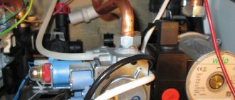
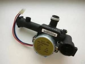
Water flow (flow) sensor for gas boiler Protherm Gepard (Panther) The DHW water flow (flow) sensor is a rotating turbine with blades, the rotation speed of which depends on the intensity of water flow. From the operating experience of Protherm Gepard (Panther) gas boilers, it is known that a frequent cause of failure of the DHW heating function in these boilers is the turbine stopping due to foreign particles entering it. Although the turbine is protected from clogging by a mesh filter, it does not always cope with its task.
If, when you open the hot water tap, the boiler burner does not ignite and cold water flows from the tap, then check the serviceability of the DHW flow sensor. It is necessary to call line d.36 of the service menu, which displays the flow sensor readings. If, when the hot water tap is open, the flow readings in line d.36 are equal or close to zero, then we conclude that the flow sensor is not working.
The location of the water flow sensor is indicated by a green arrow in the figure below.
The water flow sensor is removed by pulling the fixing steel bracket to the left. After removing the bracket, you need to pull the sensor towards you and pull it out of the socket. Before removing the sensor, it is necessary to drain the water from the DHW circuit of the boiler, as described above.
To avoid failures in the operation of the flow sensor, it is recommended to supply water to the boiler through an additional tap water filter installed in front of the boiler.
Principle of operation
The three-way valve is equipped with three pipes for connecting lines. A valve is installed between them to regulate the water supply to two of the three branches. Depending on the orientation of the tap and its connection, it performs two functions:
- mixing two coolant flows into one outlet;
- division from one line to two outputs.
A three-way valve, like a four-way valve, does not shut off the channels connected to it, but only redirects the liquid from the inlet to one of the outlets. Only one of the exits can be closed at a time, or both can be partially blocked.
In the simplest version, radiators are directly connected to the boiler, in series or in parallel. It is impossible to adjust each radiator separately according to thermal power; it is only permissible to regulate the temperature of the coolant in the boiler.
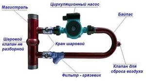
In order to still regulate each battery separately, you can insert a bypass parallel to the radiator and after it a needle-type regulating valve, with which you can control the amount of coolant passing through it.
A bypass is needed to maintain the overall resistance of the entire system, so as not to disrupt the operation of the circulation pump.
However, this approach is very expensive to implement and difficult to operate.
The three-way valve actually combines the connection point for the bypass and control valves, making the connection compact and easy to operate. In addition, due to smooth adjustment it is easier to achieve the target temperature in a limited circuit containing one or two radiators in a specific room.
If you limit part of the coolant current from the boiler and supplement it with return water returning from the radiator to the boiler, the heating temperature decreases. At the same time, the boiler continues to operate in the same mode, maintaining the set water heating; the water circulation speed in it does not decrease, but fuel consumption decreases.
If one circulation pump is used for the entire heating system, then it is located on the side of the boiler in relation to the inclusion of the three-way valve. It is installed at the return inlet of the boiler, through which already cooled water from the radiators flows, acting as a flow separator.
Hot coolant from the boiler is supplied to it at the inlet; depending on the valve setting, the flow is divided into two parts. Some of the water goes to the radiator, and some is immediately discharged in the reverse direction. When maximum thermal power is needed, the valve is moved to its extreme position, in which the inlet and outlet leading to the radiators are connected.
If heating is not needed, then the entire volume of coolant flows through the bypass into the return line, the boiler only works to maintain the temperature in the absence of real heat transfer
The disadvantage of such a connection is that it is difficult to balance the heating so that the same amount of coolant flows into each branch and to each radiator; in addition, when connected in series, the water that has already cooled down reaches the outer radiators.
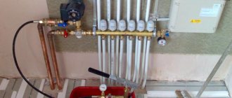
For heated floors
In multi-circuit systems, the easiest way to solve the problem of uneven heat distribution is to use a collector group with circulation pumps on each individual circuit
This is especially important in houses with two or more floors and a large number of radiators or with heated floors
The three-way valve works to mix the two flows. The line from the boiler is connected through one input, and the return pipe through the second. Mixing, the water flows to the outlet connected to the heat exchanger.
This connection diagram is especially relevant when connecting a heated floor.
It makes it possible to limit the maximum water temperature in the circuit, which is especially important, given the maximum permissible value of 35ºC at a coolant temperature from the boiler of 60ºC and above
Water circulation in the underfloor heating pipes is constantly maintained, which is necessary for uniform heating without distortions. In fact, hot water from the boiler is supplied only to heat the cooling coolant in the heated floor circuit, and the excess is discharged back to the boiler.
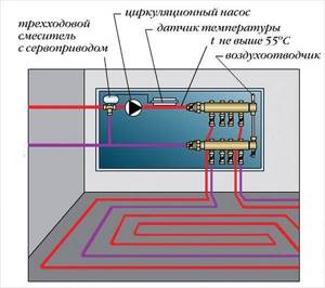
Thus, even in high-temperature heating, where the boiler heats water to 75-90ºС, it is possible to install heated floors with heating at 28-31ºС.
Three-way mixing valve for heating boiler, underfloor heating
In modern heating systems, a three-way valve is used quite often, since it is a means of high-quality regulation of the coolant - by temperature, and not by flow. After all, supplying optimally heated water to radiators is the best way to save energy.
Thermal mixing taps also have other useful functions, which you will learn about in this article. But first, it’s worth considering how a three-way valve works, and also understand its internal structure.
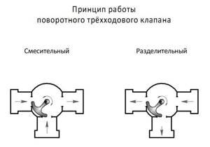
Types of 3-way valves
All thermostatic three-way valves for heating are divided into 3 types according to their design and operating principle:
- mixing;
- dividing;
- switching.
The purpose of each of the 3 varieties can be judged by its name. The first type of valve mixes two coolant flows with different temperatures, the second one separates, the third switches water between 2 lines. It is not difficult to recognize them externally; usually the principle of operation is depicted on the body in the form of a picture. Here's what a three-way mixing valve looks like:
The nameplate from Herz clearly shows the mixing of 2 flows, which means this is a mixing valve
A similar designation appears on the separating element. As for switching taps, there may not be an image on their body, but there are significant external differences in shape.
Separating (photo left) and switching (right) 3-way valve
By mixing or separating flows, the optimal temperature of the coolant supplied to the radiators of the heating system or underfloor heating circuits is achieved. Switching is used in gas double-circuit boilers, when heated water must be alternately directed to different heat exchangers.
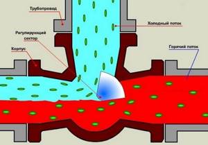
Design and principle of operation
To understand what the thermo-mixing three-way valve of the most common saddle type consists of and how it works, you should study the diagram below. Inside the brass body with three nozzles, 3 chambers are arranged using the casting method, the passages between which are blocked by poppet valves. They are fixed on one axis - a rod coming out of the body on the fourth side.
Why is condensation dangerous for a boiler?
When lighting a solid fuel boiler, you have to deal with the fact that the cold coolant washes the walls of the already heated combustion chamber, cools them, which leads to condensation of water vapor, which is invariably present in the flue gases. Water particles, interacting with flue gases, form acids, which leads to the destruction of the inner surface of the combustion chamber and chimney.
But the negative effect of condensate is not limited to this: soot particles that settle on the walls dissolve in drops of water. Under the influence of high temperatures, this mixture sinteres, forming a dense and durable crust on the inner surface of the combustion chamber, the presence of which sharply reduces the intensity of heat exchange between the flue gases and the coolant. The boiler efficiency drops.
Removing the crust is not easy, especially if the boiler’s combustion chamber has a complex heat exchange surface.
It is impossible to completely eliminate the process of condensation formation in a solid fuel boiler, but the duration of this process can be significantly reduced.
Security automation
Minimum and maximum coolant pressure switch
An important element in the boiler safety system is considered to be protection against an emergency decrease in pressure in the pressure system. A fall can occur due to various reasons, including a leak, a broken expansion tank, or failed safety valves. Low pressure of the coolant can cause it to boil in the system, as well as airing it, which can lead to the cessation of circulation through the boiler and, as a result, to overheating.
These manual and thermostatic valves allow you to regulate heat consumption in radiators and heating systems. For this purpose, ergonomic handles with a hidden fastening system are used, so they have clean rounded surfaces and chrome elements for a more durable and aesthetic appearance.
This article limits the scope of the topic to electrically controlled mixing valves in oil fired boilers as the most effective way to control return temperature. Three- and four-way mixing valves are used in central heating and domestic hot water systems to ensure that the coolant returns to the boiler. The need to use them depends on several important conditions, including: the type and design of the boiler, its size, the power of the hydraulic system, and the fuel used.
Protection against such falls can be provided by installing a special relay (minimum pressure) on the pipeline next to the boiler. It is a membrane on which the coolant presses. The membrane is connected to a whole system of electrical contacts. When the pressure in the system drops below the set values, the contacts switch. As the setting point, select the minimum permissible coolant pressure values at which the system will be operational. The relay is electrically connected to the general burner control circuit. If the pressure drops, the burner will stop working.
Ensuring the correct return temperature of the heating medium on oil-fired central heating boilers is for three reasons: the need to extend the life of the boiler, to ensure that it operates with the highest possible energy efficiency and to maintain adequate “technical hygiene” in the boiler room. What happens if the temperature of the heating water returning to the boiler is too low or too high?
When the return water temperature is too low, the heat exchanger "sweating" phenomenon occurs. Flue gases from liquid fuels contain more than 50% water vapor by volume. Water is formed, which mixes with sulfur oxides, nitrogen and carbon oxides in the exhaust gases, sulfuric, nitrogenous and carbon dioxide are formed.
No less dangerous is an excessive increase in pressure. For an emergency stop of the boiler when the pressure rises above operating values, a maximum pressure switch is used. It is similar to a minimal relay, but only has the opposite purpose - it switches contacts above the setting point. The relay is also included in the electrical circuit of the burner.
Both types of relays come with automatic restart and manual restart.
In the first case, when the parameters are normalized, the electrical contacts return to their original state and the boiler automatically resumes its operation.
In the second case, operator intervention will be required to start the relay. Typically this type of relay has two contacts. One is connected to the burner, the second is connected to a signaling device (lamp, buzzer). When the relay is triggered, the panic button will turn on.
What is it and why is it needed
This is what a classic three-way valve for a heating system looks like.
As the name suggests, this valve has 3 strokes. You can even call it a tap, since it refers to shut-off and control valves. In appearance it is an ordinary tee, but inside its structure is much more complicated. Roughly speaking, it serves to change the temperature of the water. There are two methods: in the first, the return is mixed with the supply to lower the temperature; the second method, on the contrary, separates the flows, discharging hot water into the return line. This is useful in different cases:
- Warm floor . The return and heating supply are connected to the valve. Since the return is colder, water at a lower temperature is supplied to the floors. At the same time, the temperature of the rest of the heating remains the same.
- Temperature maintenance . For normal operation of almost any heating equipment, it is necessary that the return flow is not 60 degrees colder than the supply. Otherwise, the boiler will not last long. Therefore, the valve takes water from the supply and sends it to the return.
- Condensation protection . For the same reason. If water warmer than the dew point enters the heat exchanger, condensation begins to accumulate on it.
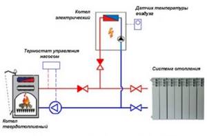
- Overheat protection . Modern boilers are equipped with various sensors. If it is, for example, a simple solid fuel boiler, it will continue to work even if it overheats. The three-way valve solves this problem.
- For piping an indirect heating boiler . To have hot water in the house, you can connect a boiler to the boiler. And then the water will be heated using heating. The three-way tap serves for uninterrupted supply of hot water. It opens when the water temperature in the boiler drops.
- When organizing a bypass . In some cases, it is necessary to direct water along an alternative path - a bypass. For example, for more efficient heating. The easiest way to do this is through a three-way valve. It will open and close at the right time.
But why install a valve when you can simply reduce the temperature? The question seems logical, but in fact, in conventional boilers at low temperatures, the heat exchanger quickly fails. A condensing boiler is better suited for this mode of operation, but their price is much higher. Therefore, it is better and easier to install a three-way valve.
As you can see, there are quite a lot of ways to use it. In some cases, it is used to improve the energy efficiency of the system. In others, it is an indispensable device for connecting equipment.
Installation and operation
To install a three-way valve successfully, it is important to follow the drawings and step-by-step instructions
You also need to pay attention to several nuances of the upcoming installation:
To properly install a three way valve, it is important to follow the drawings and step-by-step instructions
To properly install a three way valve, it is important to follow the drawings and step-by-step instructions
On the body of the tee there is a special diagram with arrows that show in detail the direction of water flow. Its presence significantly simplifies installation work and allows you to quickly and accurately connect important components. When welding metal mechanisms, the temperature flow in the joint area must not be allowed to exceed +100 °C
It is important to ensure that scale or dirt does not penetrate the system, otherwise this can lead to irreparable consequences. To install the tee, you need to choose a place that will be easy to reach for repairs or maintenance. If the tap has to pass insufficiently high-quality liquid, it is recommended to additionally equip it with filter units. The method of fixing the product can be both vertical and horizontal
This does not affect work efficiency in any way. As for the valve, it is installed directly in front of the circulation pump.
In order for the tee to function for a long time, reliably and efficiently, it is necessary to take into account the operating rules and maintain it on time. The service life of the device depends on proper and correct use.
Functional application of the device
If we consider the flow switching mechanism from the point of view of possible functionality, it should be noted that the devices differ in their operating principle:
- Dividing.
- Switching.
- Mixing.
The separation principle of operation involves dividing the flow, directing it into two circuits.
The switching function provides for the organization of switching between devices that consume thermal energy. For example, switching between the DHW and heating circuits of a double-circuit gas boiler.
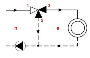
Switching functionality of the valve (classical diagram): P – primary circuit; B – secondary circuit; 1, 2 – direct transport channel; 3, 2 – corner transport channel
The switching functionality allows you to organize efficient switching between various devices that generate thermal energy:
- water heaters;
- heat pumps;
- solar panels, etc.
Another function of a three-way valve for a domestic gas boiler is mixing. It allows you to organize controlled mixing of working fluid flows (mixing return flow into the heated coolant).
To do this, it is enough to install a three-way valve on the return pipe of the heating system.
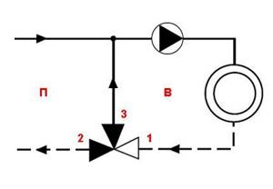
Mixing functionality of the valve (classical diagram): P – primary circuit; B – secondary circuit; 2, 1 – direct transport channel; 2, 3 – corner transport channel
Now, after a brief acquaintance with the design details of the device, we can consider the features of checking the operation of a three-way valve installed in the gas boiler circuit.
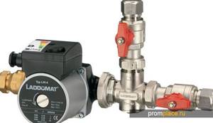
How to install a mixing valve yourself
This installation scheme is used mainly in boiler rooms of those heating systems that are connected to a hydraulic separator or to a free-flow collector. And the pump located in circuit No. 2 ensures the required circulation of the working fluid.
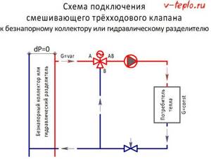
Note! If the three-way valve will be connected directly to a bypass heat source connected to port B, then it will be necessary to install a valve with a hydraulic resistance equal to the same resistance of this source
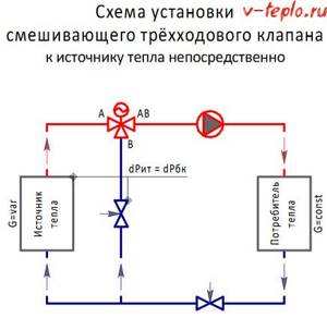
If this is not done, then the flow rate of the working fluid in the segment A-B will fluctuate in accordance with the movement of the rod. We also note that this installation scheme provides for the possible cessation of liquid circulation through the source if the installation was carried out without a circulation pump or a hydraulic separator in the main circuit.
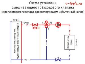
It is not advisable to connect the valve to heating networks or a pressure manifold in the absence of devices that throttle excessive pressure. Otherwise, the fluid flow in section A-B will fluctuate, and significantly.
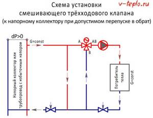
If overheating of the return is allowed, excessive pressure is eliminated by means of a jumper installed parallel to the valve connection in the circuit.
How to check a three-way valve for functionality
First of all, an external inspection should be carried out: there should be no cracks in the plastic and metal casing. As for the regulator, it should turn smoothly in all directions. To check the thermal head, it needs to be heated. For example, a hair dryer. In this case, the rod should move in accordance with the indicators. If the valve has an electric drive installed, you can check its functionality using a tester, but to do this you will have to disassemble the electric drive.
Conclusion
Three-way valves only resemble a tee in appearance. Their design is much more complex, and their applications are quite diverse. Choose a valve responsibly; consider only models from well-known, reputable manufacturers; fortunately, there are plenty of them. And then this small but very important device will work for many years without causing problems.
Boiler room equipment
Options for working connection schemes
Heating systems are very diverse and the presence of a check valve is not necessary in all of them. Let's consider several cases when its installation is necessary. First of all, a check valve must be installed on each of the individual circuits in a closed circuit, provided that they are equipped with circulation pumps.
Some craftsmen strongly recommend installing a spring-type check valve in front of the inlet pipe of the only circulation pump in a single-circuit system. They motivate their advice by the fact that in this way pumping equipment can be protected from water hammer.
This is in no way true. Firstly, installing a check valve in a single-circuit system is hardly justified. Secondly, it is always installed after the circulation pump, otherwise using the device loses all meaning.
If two or more boilers are included in the heating circuit, the occurrence of parasitic flows is inevitable. Therefore, connecting a check valve is mandatory
For multi-circuit systems, the presence of a reverse-acting shut-off device is vital. For example, when two boilers are used for heating, electric and solid fuel, or any others.
When one of the circulation pumps is turned off, the pressure in the pipeline will inevitably change and a so-called parasitic flow will appear, which will move in a small circle, which can lead to trouble. It is impossible to do without shut-off valves here.
A similar situation arises when using an indirect heating boiler. Especially if the equipment has a separate pump, if there is no buffer tank, hydraulic arrow or distribution comb.
Here, too, there is a high probability of a parasitic flow, to cut off which a check valve is needed, which is used specifically for arranging a branch with a boiler.
It is mandatory to use shut-off valves in systems with bypass. Such schemes are usually used when converting a scheme from gravitational fluid circulation to forced circulation.
In this case, the valve is placed on the bypass parallel to the circulation pumping equipment. It is assumed that the main mode of operation will be forced. But if the pump is turned off due to lack of electricity or breakdown, the system will automatically switch to natural circulation.
When installing bypass units for heating circuits, the use of check valves is considered mandatory. The figure shows one of the possible bypass connection options
This will happen as follows: the pump stops supplying coolant, the check valve actuator unit ceases to experience pressure and closes.
Then the convection movement of the liquid along the main line resumes. This process will continue until the pump starts working. In addition, experts suggest installing a check valve on the make-up pipeline. This is not necessary, but highly desirable, since it allows you to avoid emptying the heating system for a variety of reasons.
For example, the owner opened a tap on the make-up pipeline to increase the pressure in the system. If, by an unpleasant coincidence, the water supply is cut off at this moment, the coolant will simply squeeze out the remaining cold water and go into the pipeline. As a result, the heating system will be left without liquid, the pressure in it will drop sharply and the boiler will stop.
In the circuits described above, it is important to use the correct valves. To cut off parasitic flows between adjacent circuits, it is advisable to install disk or petal devices
In this case, the hydraulic resistance will be lower in the latter option, which must be taken into account when choosing.
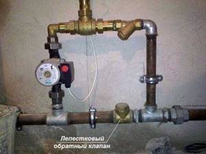
In heating systems with natural coolant circulation, the use of spring check valves is impractical. Only paddle rotators can be installed here
To install a bypass unit, it is preferable to choose a ball valve. This is due to the fact that it provides almost zero resistance. A disc-type valve can be installed on the make-up pipeline. This should be a model designed for fairly high operating pressure.
Therefore, a check valve may not be installed in all heating systems. It is necessarily used when installing bypasses of all types for boilers and radiators, as well as at pipeline branch points.
How does a three-way valve work in a heating system?
The principle of operation of the valve is to mix water flows with different temperatures. Why do you need to do this? Without going into technical details, we can answer this way: to extend the life of the heating boiler and make it more economical.
A three-way valve mixes heated water with cooled water after passing through the heating devices and directs it back to the boiler for heating. Everyone can answer the question of which water to heat faster and easier - cold or hot.
Simultaneously with mixing, the valve also separates the flows. There is a natural desire to automate the management process itself. For this purpose, the valve is equipped with a temperature sensor with a thermostat. In this case, an electric drive works best here. The quality of functioning of the entire heating system depends on the drive device.
- Such a valve is installed in those places of the pipeline where it is necessary to split the circulation flow into two circuits:
- With constant hydraulic mode.
- With variable.
Typically, a constant hydraulic flow is used by consumers who are supplied with a high-quality coolant of a certain volume. It is regulated depending on quality indicators.
Variable flow is consumed by those objects for which quality indicators are not the main ones. The quantitative coefficient is important to them. That is, for them the supply is adjusted according to the required amount of coolant.
There are also two-way analogues in the shut-off valves category. What is the difference between these two types? The three-way valve works completely differently. In its design, the rod cannot block the flow with a constant hydraulic regime.
It is always open and adjusted to a certain volume of coolant. This means that consumers will receive the required amount in both quantitative and qualitative terms.
Essentially, the valve cannot shut off the supply to a circuit with constant hydraulic flow. But it is capable of blocking a variable direction, thereby allowing you to regulate pressure and flow.
If you combine two two-way valves, you get a three-way design. In this case, both valves must operate reversibly, that is, when the first one closes, the second one must open.
Types of three-way valves according to operating principle
- According to the principle of action, this type is divided into two subtypes:
- Mixing.
- Separating.
Just by the name you can understand how each type works. The mixer has one output and two inputs. That is, it performs the function of mixing two flows, which is necessary to lower the temperature of the coolant. By the way, this is an ideal device for creating the desired temperature in underfloor heating systems.
Regulating the temperature of the exhaust ceiling is quite simple. To do this, you need to know the temperature of the two incoming streams and accurately calculate the proportions of each in order to obtain the required temperature regime at the output. By the way, this type of device, if installed and adjusted correctly, can also work on the principle of flow separation.
A three-way separation valve splits the main flow into two. Therefore, it has two outputs and one input. This device is commonly used to separate hot water in hot water systems. Experts often install it in air heater trims.
In appearance, both devices are no different from each other. But if you look at their cross-sectional drawing, there is one difference that immediately catches your eye. The mixing device has a rod with one ball valve.
It is located in the center and covers the saddle of the main passage. In a separating valve there are two of these valves on one stem, and they are installed in the outlet pipes. The principle of their operation is as follows: the first closes one passage, pressing against the saddle, and the second at this time opens another passage.
- Modern three-way valves are divided into two types according to the control method:
- Manual.
- Electric.
More often you have to deal with a manual version, which is similar to a regular ball valve, only with three pipes - outlets. Electrical automatic systems are most often used for heat distribution in private housing construction.
For example, you can adjust the temperature in the rooms, distributing the coolant depending on the distance of the room from the heating boiler. Or ensure combination with a heated floor system. Devices with large cross-country ability are installed on heat pipelines between buildings.
Like any device, a three-way valve is determined by the diameter of the supply pipe and the coolant pressure. Hence GOST, which allows for certification. Failure to comply with GOST is a serious violation, especially when it comes to pressure inside the pipeline.