Classification of combustion devices
1
BOILER combustion devices
A combustion device or firebox is a part of a boiler unit designed to carry out thermal-oxidative processes (fuel combustion) in order to obtain high-temperature combustion products. At the same time, the firebox serves as a heat exchange device in which heat is transferred by radiation from the combustion zone to the radiation heating surfaces.
By combustion method
All combustion devices are divided into layer and chamber (vortex) fuels. In layered furnaces, solid lump fuel is burned in a layer lying on the corresponding supporting surface (see Fig. 1.1).
According to the state of the fuel layer
Fireboxes are divided into layered ones with a dense suspended layer - fluidized bed (FBC).
In chamber torch furnaces
Gaseous, liquid and pulverized solid fuel is burned using special atomizing devices, otherwise called burner devices (BD).
Fuel combustion in vortex furnaces is carried out in a suspended state of fuel, which is maintained due to the shape of the chamber and the aerodynamics of the process.
Layer fireboxes,
for burning various types of solid fuel, they are divided into internal and external, with horizontal and inclined grates.
Fireboxes located inside the boiler lining are called internal.
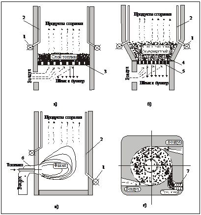
Rice. 1.1. Methods of fuel combustion: a - layered (dense layer); b - layered (weighted layer); c - chamber in the torch; d—chamber vortex. 1 - collector; 2 — screen pipes; 3 - grate; 4 - immersed heating surfaces; 5 — air distribution grille (ADG); 6 — burner device; 7 — fuel supply screw
Fireboxes located outside the lining and additionally attached to the boiler are called remote.
Depending on the method of fuel supply and organization of maintenance, layered fireboxes are divided into manual, semi-mechanical and mechanical.
Manual
are called fireboxes in which all three operations - supplying fuel to the firebox, drilling it and removing slag (focal residues) from the firebox - are performed manually by the fireman. These fireboxes usually have a horizontal grate. Such fireboxes are usually called fireboxes with a manual grate (RKR).
Semi-mechanical
are called fireboxes in which one or two operations are mechanized. Such fireboxes include shaft fireboxes with inclined grates, where fuel, loaded into the firebox manually, moves along the inclined grates under the influence of its own mass as the lower layers burn out. Fireboxes with mechanical or pneumomechanical spreaders with rotary grate bars (PZ-RPK).
Mechanical
are called fireboxes in which all three operations are mechanized. These include fireboxes: with a movable grate (LTSR - belt chain grate, ChTSR - scaly chain grate, BCR - non-failing chain grate) and a fixed layer; with a moving bed and a fixed grate - fireboxes with a rustling strip (TSH), etc.
1
Date added: 2016-06-22; views: 9258; ORDER A WORK WRITING
Find out more:
CLASSIFICATION OF FIRES AND GENERAL CHARACTERISTICS OF PROCESSES
Fuel combustion in boilers and various technological devices is carried out in combustion devices (furnaces). When using physical and chemical heat from the exhaust gases of industrial furnaces as an energy source, various devices are used to supply such a coolant to the boiler.
The general classification of combustion devices is shown in Fig. 28
According to their purpose, all fireboxes can be divided into thermal, power and technological.
Thermal furnaces are designed to convert the chemical energy of fuel into physical heat of high-temperature gases for subsequent transfer of the heat of these gases through heating surfaces to the heated medium (water, steam).
Power furnaces are used to produce combustion products not only at high temperatures, but also at high pressure. These combustion products are used directly for power purposes in gas turbines, jet engine nozzles, piston engines, etc.
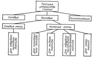
Rice. 28. General classification of combustion devices
In technological furnaces, the combustion of fuel or the occurrence of exothermic reactions during the processing of raw materials is combined with the use of the heat released in the boiler elements. We will consider mainly the thermal furnaces of boilers, as well as some directly related combustion devices for technological purposes.
As shown earlier, thermal furnaces are divided into layer furnaces for burning lump fuel and chamber furnaces for burning gaseous and liquid fuels, solid fuels in a pulverized (finely crushed) state, as well as for burning a mixture of fuels. Layer and chamber fireboxes, in turn, can be classified according to a number of characteristics (Fig. 29).
Regardless of the combustion organization scheme, the total combustion time of any fuel in the boiler furnace τr consists of the time required for supplying the oxidizer to the fuel (mixture formation), τcm, the time of heating the combustion components to the ignition temperature τн and the time required for the chemical combustion reaction itself, τх i.e.
τr= τcm+ τn+ τx
The mixing and heating steps are physical
stage of the process τf, and the combustion reaction -
chemical
τx.
If τf<< τх then the process is, as is known, in the kinetic region. The total combustion time of the fuel is determined in this case by the rate (kinetics) of the chemical process. For the kinetic region
τr ≈ τх
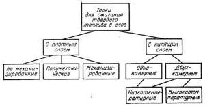
Rice. 29. Classification of layer fireboxes
When τf>> τx, i.e., when the time of transport of the oxidizer to the fuel is much longer than the time required to carry out the chemical combustion reaction itself, the process is in the diffusion region, for which τr ≈ τx.
If the time of a chemical reaction is commensurate with the time of the physical stage (τх ≈ τф), then the process is in the intermediate region and the total fuel combustion time τr is determined by the speed of the slowest stage.
When burning gaseous fuels
The physical stages of the process are the formation of a flammable mixture of gas and oxidizer (air) and heating it to the ignition temperature. The combustion of the gas-air mixture proceeds with a fairly intense heat release, so it takes little time to warm it up until it ignites. In addition, heating often occurs in parallel with the completion of mixture formation, so it does not require additional time. Thus, practically of the preparatory stages of the physical stage, the decisive one is the mixing stage, i.e. τf ≈ τcm.
Rice. 30. Scheme for supplying gas and oxidizer to the furnace:
Вг—fuel supply; VIв - air supplied together with fuel; VIIв - air supplied separately
The time τcm depends on the method of supplying gas - fuel and oxidizer - to the furnace (Fig. 30).
When a pre-mixed gas-air mixture (VIв=Vв; VIIв=0) is fed into the furnace through the burner, we have τcm =0. kinetic principle takes place
organization of the fuel combustion process.
When combustible gas and oxidizer are supplied separately to the furnace (VIв=0; VIIв= Vв), when τcm has the greatest value, the diffusion principle
, and when a partially mixed mixture is fed into the furnace (VIв>0; VIIв>0) -
a mixed principle
of organization combustion process of gaseous fuel.
Rice. 31. Scheme of combustion of a drop of liquid fuel: 1—fuel liquid; 2—fuel pairs; 3 - combustion zone; 4 - area of diffusion of oxidizer and combustion products
When burning liquid fuel in a chamber furnace
The physical stages of the process are the stages of preliminary fine atomization of fuel into small drops, heating them, evaporation and formation of a combustible mixture. The chemical stage of the process is the combustion stage of this mixture. The combustion diagram of a drop of liquid fuel is shown in Fig. 31.
Solid fuel combustion process
also consists of a number of successive stages.
First of all, mixture formation and thermal preparation of the fuel
, including drying and release
of volatiles.
The resulting flammable gases and coke residue, in the presence of an oxidizer, then burn to form flue gases and a solid non-combustible residue - ash.
The longest stage is the combustion of coke -
carbon, which is the main combustible component of any solid fuel. So, for example, for anthracite the carbon content per combustible mass is 93-95, and for firewood and peat 50-60%. Therefore, the combustion mechanism of solid fuel is largely determined by the combustion of carbon.
15.2 Performance indicators of combustion devices
A number of requirements are imposed on modern combustion devices of boilers: the combustion device must provide the specified thermal power of the installation with the production of coolant of the required parameters; it must be reliable under long-term operation conditions, safe and easy to maintain; when the furnace is operating, fuel combustion should be as complete as possible with minimal losses from chemical and mechanical incomplete combustion; it should be possible to change the boiler load in a fairly wide range; the firebox should have a relatively low energy consumption for its own needs; the possibility of using reserve fuel must be provided.
The main indicators of the combustion device are:
1) suitability for burning this fuel;
2) thermal performance MW,
Q=ВрQрр ;
3) coefficient of excess air at the exit from the furnace αт
4) heat loss from chemical incomplete combustion qх.н, %;
5) heat loss from mechanical incomplete combustion qm.n, %;,
6) apparent volumetric heat release density in the furnace qv, MW/m3, characterizing the possibility of combustion of fuel in a unit volume of the furnace Вр, kg/s (or m3/s) with available heat Qрн, MJ/kg (or MJ/m3 with minimum permissible values qx.n and qm.n
qv= ВрQрр/Vт;
7) apparent heat flux density of the combustion mirror (for layered furnaces) qR, MW/m2, characterizing the possibility of combustion on a grate with an area of R, m2, fuel in the amount of Bp, kg/s, with a heat of combustion Qrn, MJ/kg, at the minimum permissible values qх.н and qм.н
qR= ВрQр/R;
 apparent heat flux density, MW/m2 through the firebox section with area Ft
qF= ВрQрр/Fт;
9) the proportion of ash carried away by gases from the furnace, aun;
10) required air pressure before the firebox - p, Pa;
11) blast air temperature tв °С.
Design of the main elements of steam boilers
Content
- Combustion devices
- Steam-generating heating surfaces
- Steam boiler manifolds
- Superheaters
- Tail heating surfaces
- Steam boiler fittings
- Lining and insulation of steam boilers
- Frame, cladding, foundations and supports of steam boilers
Since the main type of boilers used as main and auxiliary boilers on ships with a boiler-turbine power plant (boiler-turbine power plant) are water-tube steam boilers with natural circulation, all subsequent material (unless otherwise stated) will be devoted to this type of steam boiler.
Combustion devices
Combustion devices for burning fuel oil consist of two main parts: a fuel nozzle designed for atomizing fuel, and an air guide device that ensures such organization of air supply that it is well mixed with atomized fuel, fuel is heated and evaporated, continuous ignition of the fuel-air mixture and stable its burning.
Combustion devices can be located on one or both fronts of the boiler, as well as on the side, top or bottom of the firebox. The number of combustion devices installed on the boiler can be from one (on auxiliary boilers) to 8 ÷ 16 (on main boilers). The lower the performance of each nozzle and the more of them are installed at the front of the boiler, the easier it is to achieve high quality mixture formation and combustion processes. But installing a large number of nozzles significantly complicates the design and operation of the boiler, the possibility of coking of idle nozzles increases and air leaks into the furnace through the gaps of idle VNU increases.
The following types of nozzles are used in ship steam boilers:
- mechanical - in injectors of this type, fuel is atomized due to the pressure created by the fuel pump. The fuel stream is pre-twisted in the vortex chamber and exits into the firebox in the form of a cone through a tangential hole. Mechanical injectors provide high atomization quality and are reliable, but have a small range of fuel consumption control. One type of mechanical nozzle is the rotary nozzle. In it, fuel is atomized due to the centrifugal forces of the rotating parts of the nozzle itself. But rotary nozzles are difficult to manufacture and less reliable in operation;
- air and steam (pneumatic) - these nozzles use the ejection effect, as a result of which a moving stream of air or steam carries fuel particles with it. The fuel flows to the nozzle by gravity from a supply tank installed above the nozzle, and under the influence of the kinetic energy of the steam or air jet, it is crushed into tiny droplets. Pneumatic nozzles have a simple design, are less demanding on the processing of parts, but to ensure high-quality atomization, their operation requires a large consumption of steam or air;
- steam-mechanical - combine the advantages of mechanical and steam nozzles. The nozzle tip has two channels: oil and steam. At high fuel flow rates, this nozzle operates like a conventional mechanical one, and at low flow rates, additional steam is supplied to ensure high-quality fuel atomization.
Air directing devices of steam boilers must have the following properties: ensure high quality and stability of torch combustion with minimum excess air ratios and the minimum possible hydraulic resistance of the boiler front; be able to regulate air flow rates in a wide range of boiler loads, while ensuring sufficiently high air flow rates at reduced load modes;
The following types of VDU (air guide device) are used in ship steam boilers:
- VNU with swirlers. In these devices, the air flow is swirled using a blade guide device - a swirler. The air passing through the blade apparatus of the swirler receives a rotational movement around the axis. Moreover, the air is swirled in the direction opposite to the swirl of the fuel jet in the nozzle in order to better crush the fuel and better mix it with air;
- axial VNU with stabilizers. In devices of this type, the aerodynamic conditions necessary for organizing a combustion source in a torch are created as a result of the interaction of an axial air stream with a conical stabilizer installed on the nozzle. When air moves behind the stabilizer cone, a rarefaction zone is created, causing a reverse flow of gases directed towards the flow of atomized fuel. The stabilizer is also a flow turbulator;
- combined VNU - these devices use combinations of swirling and unswirling flows. Typically, two-zone VNUs are used, in which the central air flow is swirling, and the peripheral air flow is axial. The main advantage of combined VPU is the ability to regulate air flow by rotating the blades: when operating at full load, the blades of the central zone are rotated along the air flow and the device operates like a conventional axial VPU with a stabilizer; As the productivity of the nozzles decreases, the blades rotate to a certain angle, providing swirling air flow.
The design of the combustion device of the auxiliary boiler type KVVA with a steam-mechanical nozzle and a combined single-zone air guide device is shown in Fig. 20.
Steam-generating heating surfaces
Heat is transferred from the torch and gases to the boiler water and steam-water mixture through heating surfaces located in the path of fuel combustion products. During the heat transfer process, the temperature of the gases decreases from 1800 ÷ 2000 °C in the furnace to 190 ÷ 500 °C at the outlet of the boiler. Heat transfer in the boiler is carried out by all existing methods of heat exchange - thermal conductivity, convection and radiation.
Steam-generating (evaporative) surfaces are those heating surfaces of the boiler in which, due to the heat of combustion of the fuel, the boiler water is converted into steam. Depending on which method of heat transfer in a given heating surface is dominant, screen and convective steam-generating heating surfaces are distinguished.
Screen heating surfaces include pipes that directly limit the combustion space and are illuminated by a torch. In screens, the main amount of heat (80 ÷ 90%) transferred to water is the heat of the torch radiation, and only 10 ÷ 20% of the transferred heat is due to convective heat exchange. For this reason, screen heating surfaces are also called radiation-receptive or radiation. Screen heating surfaces are made, as a rule, in the form of a solid wall of pipes arranged in one row (less often - in two rows), without gaps between the pipes (Fig. 21.a).
The space located behind the screen bundle of pipes is unheated, and in modern ship boilers, unheated lower pipes are placed in it.
Convective steam-generating heating surfaces are those surfaces in which the main amount of heat (90 ÷ 95%) is transferred due to convection when pipes are washed by a flow of gases at a high temperature. Such heating surfaces can have a checkerboard or corridor structure (Fig. 21.b, c). Each type of structure of the convective heating surface has its own advantages and disadvantages: the staggered arrangement of pipes causes greater turbulence of the gas flow flowing around the pipe, and, accordingly, a greater intensity of heat exchange, but provides significant aerodynamic resistance to moving gases.
Steam boiler manifolds
All pipes of the evaporation and lowering parts of the boiler are attached at their ends to the collectors (steam and water) using the rolling method. Sometimes, in high-stress boilers, pipes can be fastened by welding, or by a combined method (rolling and welding).
Steam boiler collectors (Fig. 22) are welded cylindrical steel thick-walled structures. For large-diameter (steam) collectors, the bottoms have an elliptical shape. The manifold shell at the place where the pipes are attached has a thickened structure and is called a tube sheet. All collectors, to ensure inspections and repair work, have manhole holes in the bottoms with manhole valves. Various partitions, partitions and other internal devices are installed inside the collectors.
The internal collector devices of the steam collector (depending on the boiler design) may include the following devices:
- various types of separation devices: perforated shields, louvered separators, intra-collector cyclones, etc., providing steam separation - separation of steam from water from the steam-water mixture and reduction of steam humidity;
- a feed pipe that ensures uniform distribution of feed water throughout the collector and its supply to the downpipes;
- steam sampling devices: steam collecting pipes or steam baffles that ensure the selection of saturated separated steam from the steam manifold and its supply to the superheater;
- funnels and pipes of the boiler water sampling system;
- funnels and pipes of the boiler top blowing system;
- desuperheater pipe system.
Internal collector devices of water collectors and superheater collectors are designed mainly to uniformly distribute media along their length and organize the movement of these media. The internal collector devices of water collectors and superheater collectors include various types of shields, baffles, bypass pipes, and pipelines of blowing systems.
Superheaters
Superheaters are those boiler heating surfaces in which dry saturated steam is superheated to the required temperature. These heating surfaces can be made: radiation - in the form of a screen in the boiler furnace; radiation-convective - in the form of a flooded pipe bundle; convective - in the form of a convective bundle of pipes located in one place or another of the boiler flue. Unlike evaporative heating surfaces, in steam superheaters there is always a forced movement of the medium (steam) due to the pressure difference in the steam manifold and behind the main stop valve of the boiler. This circumstance gives more freedom in choosing design designs for superheaters.
Currently, the following types of superheaters are most often used in marine and ship steam boilers:
- vertical loop superheater (Fig. 23.a) - structurally consists of a collector divided by a longitudinal partition into two cavities, and rows of pipes made in the form of loops and connecting the collector cavities. This type of superheater is usually located in the gas duct behind the convective evaporation bundle (Fig. 19.b), or inside the evaporation pipe bundle (Fig. 8.b);
- vertical double-collector superheater (Fig. 23.b) - consists of lower and upper collectors connected by rows of pipes. This type of superheater is usually located behind the convective steam-generating heating surface of the boiler;
- horizontal coil superheater (Fig. 23.c) - its design includes two small-diameter collectors connected by rows of pipes made in the form of parallel-connected coils. This type of superheater fits well into the vertical flue of the boiler and is located behind all evaporative heating surfaces.
Tail heating surfaces
The tail heating surfaces of the boiler are those located at the very end of the gas path. Such heating surfaces include water economizers and air heaters.
The use of tail heating surfaces is associated with the desire to ensure high efficiency of the steam boiler with its minimum weight and size parameters. Moreover, the higher the steam parameters produced by the boiler, the greater the feasibility of installing them.
All domestic main steam boilers are required to be equipped with water economizers. The installation of an air heater is not carried out on all boiler designs, since the presence of this heating surface complicates the design and operation of the boiler, and significantly increases its weight and dimensions. This is due to the fact that the process of heat transfer from gases to air proceeds much worse than from gases to water in evaporative heating surfaces. Therefore, air heaters have dimensions that are much larger than those of other heating surfaces. Installing air heaters in high-pressure boilers is generally impractical, since the air after compression in the TNA compressor has a fairly high temperature: 160 ÷ 170 ° C.
Water economizers (Fig. 24) are essential elements of a modern steam boiler and are designed to preheat feedwater before feeding it into the steam manifold using the heat of the flue gases leaving the boiler.
Preheating water allows you to reduce the size of the evaporating part of the boiler and reduce fuel consumption for heating water in the evaporating part. Depending on the degree of heating of the feed water in economizers, they are divided into non-boiling and boiling. In non-boiling economizers, the feed water is subheated to a boiling point of several degrees. Such underheating of the feed water to boiling somewhat reduces the efficiency of the boiler, but ensures more reliable operation of the economizer. Boiling economizers are not used in ship boiler plants.
Currently, the following types of economizers are used in steam boiler designs:
- smooth-tube economizers.
- fin economizers with solid and hollow fins;
- finned economizers with solid and star-shaped steel or silumin fins;
The use of fins or fins significantly increases the heat-receiving surface of economizers, thereby making it possible to reduce their dimensions, but leads to a number of significant drawbacks: reduced operational reliability, complication of manufacturing, repair and operation technology. The greatest preference in the domestic boiler industry is given to smooth-tube economizers.
Air heaters for steam boilers are designed to preheat the air entering the boiler furnace. The supply of heated air to the firebox improves the conditions for the combustion process and helps to increase the temperature of the gases in the firebox and boiler flues. The use of air heaters allows increasing the boiler efficiency by 3 ÷ 5%.
The type and design of the air heater used largely depends on the design of the boiler itself, its purpose and the specified degree of efficiency. Air heaters used in steam boilers can be classified according to the following criteria:
- by the method of heat transfer: recuperative, in which heat is transferred to the heated air through the heating surface; regenerative, in which heat transfer occurs due to alternate washing of the heat-accumulating surface with hot gases and heated air;
- by type of heating medium: gas; steam; water;
- by type of heating surface: smooth and ribbed;
- according to the profile of the heating surface: plate and tubular;
- according to the number of air and gas passages: one-, two-, three- and four-pass;
- by pipe arrangement: vertical and horizontal.
Two types of air heaters are widely used in ship boilers:
- steam, in which the heating medium is exhaust steam;
- gas, the heating medium in which are combustion products.
Steam air heaters cannot provide high air heating temperatures. In addition, steam air heaters are more expensive than gas heaters due to the use of steam lines and steam fittings. Therefore, gas recuperative air heaters have become more widespread in ship boilers.
In recuperative air heaters, fuel combustion products usually wash the pipes from the inside, and the heated air moves in the interpipe space (Fig. 25.a). There are also reverse circuits of air heaters with air movement inside the pipes (Fig. 25.b). The compactness of the design of air heaters can be significantly increased by finning the surface on the air side, and an increase in the temperature of the heated air can be achieved through the use of several sections located one behind the other.
Regenerative air heaters are much lighter, more compact and cheaper than recuperative ones. They are based on a slowly rotating rotor, washed alternately by hot gases and cold air (the design of regenerative air heaters is described in more detail in the section on gas turbine units). But regenerative air heaters have not become widespread in domestic boiler installations due to their tendency to become dirty, difficult to operate, and large air leaks into the chimney.
Steam boiler fittings
According to the functions they perform, the fittings of steam boilers can be divided into the following groups:
- fittings for controlling the operation of the boiler: feed, fuel valves and valves for the selection of saturated and superheated steam;
- boiler protection system fittings: pulse, safety valves, valves of quick-closing boiler shutdown devices;
- physical and chemical control fittings: valves for sampling, adding additives, upper and lower blowing, water indicating devices;
- additional fittings: air release valves, drainage valves, connections to instrumentation and control devices.
As a rule, the following set of fittings is installed on all types of water tube boilers:
On the steam manifold:
- manual feed valve (one or two) – for manually regulating the supply of feed water from the economizer to the boiler;
- automatic feed valve – part of the boiler power regulator;
- feeder non-return valves - ensure the supply of feedwater only in the direction of the steam header, and prevent the loss of water from the boiler if the feed pipe ruptures;
- main safety valves (at least two);
- impulse safety valves;
- control safety valves;
- auxiliary stop valve – for taking saturated steam from the steam manifold;
- water indicating devices (at least two: left and right) - for visual monitoring of the water level in the steam manifold;
- top blow valve;
- communication valves to the condensation vessel;
- pulse valve to the power regulator;
- boiler water sampling valve;
- air release valves on the steam transfer pipe, condensing vessel and auxiliary stop valve.
- desuperheater valves (if the boiler includes a desuperheater).
On the water manifold:
- boiler bottom blowing valves (at least two).
On the upper superheater manifold:
- pulse valve to the power regulator;
- air release valve.
On the lower manifold of the superheater:
- main stop valve (MSV) – for removing superheated steam from the boiler;
- two drain valves;
- pulse valve to the BZU (boiler quick-closing device);
- pulse valve to RDP (steam pressure regulator);
- GSK purge valve.
On the economizer and communication pipe:
- economizer drain valve;
- boiler acid flush valve;
- air release valve.
Lining and insulation of steam boilers
The operation of a steam boiler is accompanied by significant heat generation, affecting not only the heating surfaces, but also other structural elements of the steam boiler. To protect the metal elements of the internal casing from high temperatures, all structures not covered by heating surfaces are covered with a layer of thermal insulation.
The following are used as insulation in steam boilers: asbestos, fireclay bricks, refractory ceramic products, refractory silicon carbide products, sovelite slabs.
Brickwork (lining) covers all the walls of the firebox and flues (Fig. 26, 27) up to the area where the gas temperature does not exceed 600 °C (usually the economizer area). The bricks are usually square in shape and are attached to the inner casing through a layer of asbestos cardboard. More heat-stressed bricks located in the firebox area are attached to the elements of the internal casing of the boiler using individual bolts. The bolt heads are recessed into the bricks, and the recesses are filled with mortar - a mixture of fireclay powder, refractory clay and sand. Less thermally stressed bricks are attached to the inner casing of the boiler with T-bars, into which they fit with their grooves.
The bricks from which the tuyeres of combustion devices and inspection devices are laid (Fig. 27) have complex shapes with beveled edges.
The brickwork is done in such a way that on the side of the flue the surface is smooth, without ledges (Fig. 26). In the area of transitions from one brick thickness to another, the internal casing of the boiler is stepped. In the region of maximum temperatures in high-stress furnaces, brickwork can be made in two layers: the bottom layer is fireclay brick; the top layer is fire-resistant silicon carbide products.
The lining is one of the most expensive parts of steam boilers. The weight of brickwork in some steam boilers can reach 10 tons or more.
To insulate the outer casing of the boiler and collectors, sovelite slabs are used, laid on a sovelite backing and tightened from the outside with a metal mesh. The mesh is coated with sovelite plaster on top, covered with fabric (percale or twill) and painted with silver.
Frame, cladding, foundations and supports of steam boilers
The lining of the furnaces and the insulation of the gas ducts of water-tube boilers are attached to the frame, which is usually the supporting structure for the superheater, economizer, air heater and other devices. The frame, which is the base of the internal casing of the boiler, usually repeats the configuration of the heating surfaces (evaporation and superheating tube bundles).
The outer casing of the boiler can, in principle, be of any shape. It is spaced from the inner casing at a distance of several tens of centimeters and is distanced from it by various spacer brackets, channels, brackets and squares. Thus, the outer and inner casings form a single rigid box-shaped structure. The space between the casings is used to supply air to the VNU.
The outer casing of the VNK is always made cylindrical with elliptical bottoms. This design of the outer casing is capable of withstanding increased air pressure supplied from the compressor of the turbocharger unit to the VNK furnace.
To provide access to the boiler firebox and to its internal parts, special hatches and manholes are made in the outer and inner casings, which are closed with gas-tight lids during boiler operation.
To install and securely fasten the boiler on a ship, use foundations welded to the ship's frame and supports fixed in the lower parts of the boiler (on the lower manifolds). One of the boiler supports is made motionless, with a rigid mount. As a rule, the support under the lower superheater manifold on the front side of the boiler (under the main stop valve) is stationary. The remaining supports, in order to ensure thermal expansion during boiler operation, are made movable. The mobility of the supports is ensured by the ovality of the holes for the bolts installed with spacer bushings (Fig. 28).
Literature
Ship power plants. Boiler-turbine power plants. Boldyrev O.N. [2004]
Similar articles
- Fittings for ship auxiliary boilers
- Combined recovery boilers
- Marine recovery boilers, purpose, design
- Vertical combination boiler of the Shukhov system
- Auxiliary double-circuit boiler
- Auxiliary water tube boilers
- Auxiliary fire tube boilers
- Classification of ship auxiliary boilers
- Main indicators characterizing the boiler
- Purpose of the auxiliary boiler installation and its diagram
1 Rating 1.00 (2 Votes)
Mechanical fireboxes
Mechanical boiler furnaces
Mechanical fireboxes. The difficulty of supplying small consumers with sorted fuel of certain types and deposits, insufficient qualifications of maintenance personnel and a large proportion of manual labor during maintenance require complete mechanization of the combustion devices of small boiler units. Labor-intensive and difficult operations include loading fuel onto the grate, removing slag from it, and scissoring the layer. If in the combustion process these operations are mechanized, then the firebox can be considered mechanical; in all other cases it is semi-mechanical.
Based on these provisions, combustion devices for low-capacity boiler units commercially produced in the USSR provide for the mechanization of the processes of supplying fuel to the grate and removing slag from it.
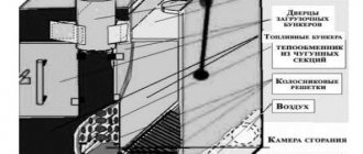
In Fig. 3-6 show mechanical fireboxes with a fuel thrower onto the burning layer, equipped with swinging grates, a section of the combustion device with a pneumo-mechanical fuel thrower 3, a grate 1, a drive to the grate, a fuel hopper 4, combustion chamber doors, a box for supplying air to the hopper is shown. , designed to collect sinkholes and slag using a slag gate.
Rice. 3-6. Section and general view of the front of a mechanical firebox with PMZ and a grid of rotary grates. 1 - rotary grate; 2 - arch above the combustion door; 3 — PMZ fuel thrower; 4 — coal box-hopper; 5 — PMZ drive.
A general view of the PMZ pneumomechanical spreader is shown in Fig. 3-7. The fuel entering the hopper with inclined partitions to prevent freezing, cascade-tray coal box L, moves to the plunger feeder 6, which has a height of 50 mm and a maximum stroke length of the plunger of 42 mm.
The movement of the plunger is transmitted through a gearbox 7 and a rocker mechanism with an eccentric, with the help of which you can change the stroke length of the plunger by 2.2 times. The slide is connected to the plunger drive shaft by a pawl and a lever, which allow you to turn off the feeder without stopping the rotation of the rotor 7, and to fine-tune the feeder performance.
The rocker connecting rod is connected to an eccentric sitting on the intermediate shaft, rotated through two pairs of gears from the rotor shaft 1. The plunger pushes the fuel onto the accelerating plate 5. By moving the plate using the flywheel, you can change the range of fuel throwing onto the grate. The height of the slab is 150 mm, the angle of inclination to the horizontal is 45°.
From the accelerating plate, fuel enters cylindrical tray 2. The rotor with blades 1 in the tray rotates at a frequency of 600 to 1100 rpm. The fuel is thrown into the combustion chamber from above onto the layer by two rows of solid blades of a wave-shaped profile; Depending on the width of the spreader, two or three blades are installed in each row. The rotor has a diameter (at the edges of the blades) of 216 mm, the tray is 232 mm. The fuel is thrown in a fan with an opening angle of 40°. On the side of the firebox, a cast-iron lance made of grate D is adjacent to the tray, under which air is supplied with a pressure of 500 - 800 Pa (50 - 80 tu of water).
Rice. 3-7. Pneumomechanical spreader PMZ-TsKTI.
The tray in which the rotor rotates has a folding plate in the middle part for inspection and removal of stuck objects and pieces of fuel. Two 4 nozzles with a cross section of 40X40 mm are installed on the sides of the spreader, the axes of which intersect inside the firebox and make an angle of 20.5° with the axis of the spreader. The lance and nozzles serve to supply air under flying pieces of fuel to pick up small particles and burn them in the volume of the combustion chamber.
Rice. 3-8. Layer thickness and fractional composition of fuel along the length of the RPK grate when feeding PMZ raw coal.
The rotor shaft is connected by an articulated coupling and a V-belt drive to an asynchronous electric motor with a power of 1.1 kW.
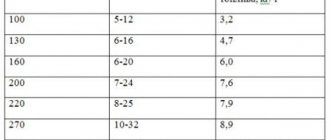
The spreader can provide, depending on its width of 350, 400 and 600 mm, a boiler unit productivity of 2; 2.2 and 3.3 kg/h (7, 8, and 12 t/h), respectively.
Sometimes spreaders are made with a scraper or plate feeder instead of a plunger feeder. The grate with PMZ is usually made from rotary grate with manual drive - RPK.
Grate bars in the form of plates measuring 300X189 mm have a width of 14, 28 and 42 mm; are freely mounted on a shaft with a rectangular cross-section of 40X60 mm, overlapping the adjacent row of grates with bevels. The live cross-section of the grate is about 5%, and the grate itself eliminates fuel failure. The distance between the axes of the shafts is 305 mm, the width of each section can be from 900 to 1300 mm, the length of the grille can be from 1525 to 3660 mm, including the front plate with a length of 495 mm. The manual drive allows you to rotate the grate by 60°. When turning the grate, partial drilling of the fuel layer occurs and part of the lower slag layer is removed. The thickness of the layer and the fractional distribution of the layer of raw coal along the length of the fixed grate with a pneumomechanical spreader according to the experiments of E. V. Nechaev are shown in Fig. 3-8.
The figure shows a decrease in the thickness of the layer at a distance of about 1.5 m from the front wall and the concentration of smaller pieces of fuel at the front of the furnace, and larger ones at the rear wall. Despite this distribution of fuel, the range of changes in α, 02 and R02 is smaller than that of a grate with manual fuel injection, as can be seen from Fig. 3-9 and comparing it with Fig. 3-2 and 3-3. The fluctuations in gas composition that take place in the PMZ-RPK furnace are explained by the fact that when manually regulating the combustion process, the fuel supply changes, but the air supply remains constant.
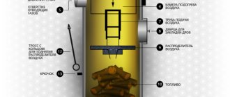
The process of burning solid fuel on a stationary grate can be mechanized by using a so-called screwing bar, which moves the fuel along the grate, drills it and pushes the slag into a special bunker. The general view of such a device is shown in Fig. 3-10.
Rice. 3-10. Mechanical firebox TShPM with a fixed grate and a rustling strip for coals and their waste. 1 - carriage; 2 — rod; 3 — bar; 4 - electric motor with gearbox; 5 - hot water boiler; 6 — hole into the firebox; 7 — grate; 8 — fuel bunker; 9 - hopper for slag.
The screwing bar 3 is driven by a special device consisting of a frame - a carriage 1 with rods 2 to which it is attached, and a mechanism connected to a chain and rotated by an electric motor 4. Limit switches are installed in the extreme positions of the frame. Rods can be made in the form of chains, pipes, channels. Fuel from hopper S, located at the front of the firebox with a rustling strip 3 (the shape of which is shown in Fig. 3-11, a), is captured and fed under the burning layer onto the grate; with the forward and backward movement of the rustling bar, pieces of fuel move and mix along the length of the grate (Fig. 3-11, b).
Rice. 3-11. Profiles (a) and operation diagram of the screw strip (b).
During the cycle, the bar carries out the movement of fuel, its drilling and removal of slag. The bar moves 80 - 85% of the time per cycle, completing it in 8 - 20 minutes. The cycle time is related to the type of fuel, grate length and the heat load of the firebox. The fuel and its slag should not sinter, and therefore the bar must be cooled with water. Mechanical fireboxes with a rustling strip have not yet found widespread use in high-power boiler installations for a number of reasons, but are actively used in KVM mechanical boilers with TShPM with a power of 0.8 to 2.5 MW.
The mechanism for supplying and moving the fuel layer, as well as removing slag, can be separated from the grate and combined with them, as shown in Fig. 3-12.
Such combustion devices are called fireboxes with inclined pushing grates or cascade ones, depending on their design.
In some designs, fuel is supplied to the grate under the layer of fuel burning on it using screws, pistons and other mechanisms (Fig. 3-12.6 and c).
Of greatest interest is the Lomshakov-Kruul (LK) mechanical furnace, designed for burning municipal waste and shale.
The general view of the grate is shown in Fig. 3-13.
The grid consists of three movable frames - trolleys with separate drives 2. The frames can move relative to each other with a number of strokes of 2 or 4 per minute to a relative length of 0, 60, 110,145, 160 mm. Fuel from bunker 4 is supplied to the pre-furnace shaft 5, from which it is supplied to the guide plate 10 and grate bars 1, then, with the help of pushing grate bars (Fig. 3-13.6), it is screwed and moved down to the last row of grate bars, where the slag lies. The grate grates have cells 50 mm deep (Fig. 3-13, c), filled with granite gravel with pieces measuring 8 - 12 mm, which is necessary to reduce fuel failure. Slag is removed from the grate into hopper 9. The angle of the grate to the horizontal is 10.5°, the length of the grate is ≈730 mm, the width is 200 mm; the resistance of a grid with cells filled with gravel is 100 -120 Pa (10 - 12 mm water column).
In gratings of this type, the combustion mirror width is from 1100 to 6500 mm and the length is from 3300 to 8800 mm, i.e., for unit productivity from 0.8 to 23 MW (from 0.7 to 20 Gcal/h).
Currently, LK fireboxes are not produced.
The mechanization of the fuel combustion process in the bed is the use of chain moving grates.
The general view of the chain grate is shown in Fig. 3-14.
The grate consists of a frame on which bearings of two shafts are mounted - drive 1 and driven 7. Sprocket gears are mounted on the drive shaft, which mesh with the driven elements of the grate web, and smooth pulleys are mounted on the driven shaft.
The grate cloth can be made of steel plate chains (scaled cloth), to which the grate holders are attached using “fingers” with cotter pins. Fingers are inserted into the holes of the holders - the tides of the grate. The chains are connected to each other by tie rods with spacer tubes and rollers placed on them.
This entire structure rests on a frame 2 of beams (rails), along which rollers roll. Once on the driven shaft pulley, the grate bars rotate, causing any remaining fuel or slag to fall out, cleaning the grate cloth. Next, the grate sheet moves to the front of the firebox. To unload the main frame, lower guide beams are installed under the canvas in the form of an additional frame 6.
Rice. 3-12. Layer fireboxes with grates that push fuel obliquely and with bottom fuel supply. a: 1 - grate; 2 - mechanisms for moving grate bars; 3 — fuel bunker; 4 - gate that regulates the thickness of the fuel layer; 5 - hopper for slag; 6 - piston or plunger; 7 - crusher for slag; b and c: I - incoming crude fuel; II - layer with escaping volatiles; /// - burning volatiles and coke; IV - zone of afterburning of fuel and slag.
Rice. 3-13. Mechanical firebox with inclined pushing grates Lomshakova - Kruul (LK). a - general view of the firebox; b - middle row grate bars; c - grate cell filled with granite gravel; 1 — grate bars; 2 — trolley drive; 3 — trolley control; 4 — pre-furnace bunker; 5 - pre-furnace shaft; 6 — air supply zones; 7 - secondary acute blast; 8 — gates for lowering the failure; 9 - hopper for slag; 10 - guide plate.
Rice. 3-14. Firebox with non-breaking chain grate. a - longitudinal section; b — view of the front.
The mass of 1 m2 of grating web is 300 - 400 kg and the total weight of 1 m2 of active grating area is 1.5 - 2.7 tons.
From the hopper 3, located at the front of the furnace, the fuel enters the grate grate 5. The thickness of the fuel layer is adjusted using a sector gate 10 and a gate 11. The speed of the grate movement can be changed by a drive 9 with a gearbox 12 sitting on the grate drive shaft.
In the combustion space, fuel is ignited from above under the influence of radiation from the arches, a torch and partial contact with the burning layer. As the grate and the fuel lying motionless on it move, the fuel dries, volatiles are released, the resulting coke burns out, and the slag burns out. The distribution of air flow in accordance with the phases of fuel combustion under the grate is carried out by box 4, divided into zones.
Rice. 3-15 Firebox with scaled chain return grate (longitudinal section and front view). 1 - front drive shaft; 2 — grille frame; 3 - coal box; 4 - grate cloth; 5- rear shaft; 6 — rear fixed grate; 7 — support rollers; 9 — chain grid drive and gearbox; 11 — PMZ drive — motor, transmission and gearbox; 12 — front casing; 14 - slag pit; 15 - PMZ; 16 - additional frame (other designations in the text to Fig. 3-14).
Rice. 3-16. General view of a mechanical firebox equipped with a chain grate with a belt blade - LCZ and PMZ.
Rice. 3-17. Longitudinal section of a firebox with a chain grate and a Makaryev pre-firebox for burning peat. Slag is removed from the grate using a slag remover 8 and dumped into a hopper for collecting slag. Chain gratings of this type are called failure-free chain gratings (BCR) with a corresponding number, and sometimes with a code (M) indicating modernization. In recent years, factories have been producing chain gratings with a flake (CCR) or tape (LTSR) web of direct and, more often, reverse motion with pneumatic fuel injection (PMF). A general view of the layout of a mechanical furnace with reverse flow CCR is shown in Fig. 3-15. Unlike the direct-flow CCR furnace, it does not have a layer thickness regulator on the grate and the slag hopper is moved to the front of the furnace. The speed of the grating can vary from 2.3 to 16.6 m/h, the open cross-section of the grating web is 5%, the electric motor power is from 4 to 12 kW.
A grate with a LCR strip cloth differs from a mechanical firebox with a scaly CCR in that the cloth is assembled from five types of grates, some of which are leading. They are a chain link driven by a sprocket. A general view of the design of a mechanical firebox with a reverse LCR with a pneumomechanical thrower is shown in Fig. 3-16. The view from the front of both mechanical fireboxes is the same; the mass of 1 m2 of the grate sheet of the LCR grate is about 430 kg; movement speed from 2.04 to 13.9 m/h, open area - 5%, power of electric grating motors from 1.4 to 4.0 kW and pneumo-mechanical spreader - 1.1 kW.
To burn sod peat on chain grates, mechanical furnaces are used with preliminary preparation (drying) of fuel in the pre-furnace chambers of the Makaryev system (Fig. 3-17). Fuel preparation is carried out at special stages 1 by creating and maintaining combustion sources. The steps consist of chilled beams lined or protected with a fire-resistant mass. To maintain combustion, up to 15% of air heated to a temperature of 250°C is introduced into the combustion chamber.
The Makaryev firebox allows you to economically burn sod peat with the addition of up to 30% milled peat by weight at a fuel moisture content of up to 50%. Chain grates with pre-furnaces are used for burning peat under boilers with a capacity of up to 2.8 kg/s (50 t/h) or up to 35 MW (30 Gcal/h) using commercially produced grates.
The design of the pre-furnace is carried out either by the manufacturer of the boiler unit, or by the design organization developing the boiler room.
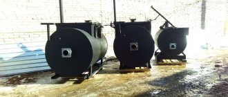
Rice. 3-18. Mechanical furnaces with a fluidized (boiling) bed of fuel in an energy technology plant.
Higher intensification of the fuel combustion process in the bed can be achieved by burning fuel in a semi-suspended state - in mechanical furnaces with a fluidized fluidized bed. In these fireboxes, maintaining the fuel's air velocity requires an exact match between the speed of the air and gases and the size of the fuel particles. The complexity of the process and the difficulty of providing fluidized bed furnaces with fuel with a certain particle size have led to the fact that they are still used in technological installations (Fig. 3-18). The factory design of the combustion device and boiler unit is shown in Fig. 3-19.
Rice. 3-19. Mechanical furnaces with a fluidized (boiling) bed of fuel and its layout with installation according to Fig. 3-18.
In addition to those given, there are numerous designs of mechanical fireboxes for low-capacity boilers, but they are either being tested or are not yet perfect.
For classification and analysis, E.V. Nechaev and A.F. Lubnin (TsKTI) propose, based on the principle of movement of fuel and air flows, to distinguish the following schemes of the layer process:
- with counter flows of fuel and air; with cross flows of fuel and air;
- with parallel flows of fuel and air;
- with reversed bed (fuel and air flows on the water-cooled grate are directed downward;
- a hot layer of fuel comes into contact with the grate;
- mixed schemes.