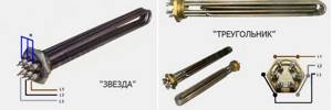
Star connections
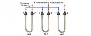
As an example, let's take a star connection with three electric heaters. In this way, you can connect dry heating elements with four terminal bolts and heating elements blocks.
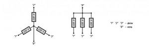
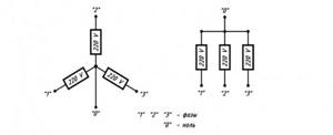
Every second output of the heating element is connected to the corresponding phase. The first terminals are connected together and form a common point, defined as zero or neutral. The connected load in this case is considered to be three-wire.
The three-wire connection is designed for an operating voltage of 380 Volts. Below we will consider the diagram for connecting a tubular heater to a three-phase network
. In this case, the voltage is switched on and off automatically using three-pole switches.
In the above diagram you can see that the heater terminals on the right are connected to phases A, B, C. The terminals on the left are connected at a common neutral point. The operating voltage between the terminals on the right and the neutral point is 220 Volts.
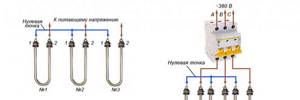
In addition to the three-wire connection, you can connect to the network using a four-wire star circuit. In this case, the heaters are connected to a three-phase network, the voltage of which is 220 Volts. The zero point of the load is connected to the neutral point of the power source.

The presented diagram shows the connection of the right terminals of the tubular heating elements to the corresponding phases, while the left ones are closed at one point connected to the neutral bus of the power source. Between zero and the heater terminals the voltage is 220 Volts.
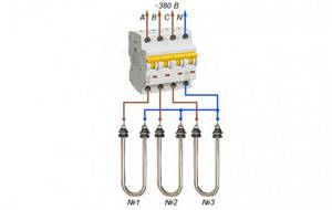
If you need to completely disconnect the load from the electrical network, “3+N” or “3P+N” switches are used, which operate in automatic mode. With the help of such machines, it is possible to completely transfer all power contacts to an automated operating mode. For a clear practical application of the “star” circuit, let’s consider connecting the electric heaters of the boiler.
Let's consider connecting a three-phase heating element through a magnetic starter and a thermal relay.
Rice. 1 The heating element is connected through one three-phase MP with normally closed contacts (Fig. 1). The starter is controlled by a thermal relay TP, the control contacts of which are open when the temperature at the sensor is below the set one. When three-phase voltage is supplied, the contacts of the starters are closed and the heating element is heated, the heaters of which are switched on in a “star” configuration.
Rice. 2 When the set temperature is reached, the thermal relay turns off the power to the heaters. Thus, a simple temperature controller is implemented. For such a regulator, you can use a RT2K thermal relay (Fig. 2), and for a starter, a third-value contactor with three opening groups.
RT2K is a two-position (on/off) thermal relay with a copper wire sensor with a temperature setting range from -40 to +50°C. Of course, using one thermal relay does not allow you to accurately maintain the required temperature. Turning on all three sections of the heating element each time leads to unnecessary energy losses.
Rice. 3 If you control each section of the heater through a separate starter connected to its own thermal relay (Fig. 3), then more accurate temperature maintenance can be achieved. So, we have three starters, which are controlled by three thermal relays TP1, TP2, TP3. The response temperatures are selected, let's say t1
Rice. 4 Relay-temperature sensors provide switching of the executive circuit up to 6A, at a voltage of 250V. To control a magnetic starter, such values are more than enough (For example, the operating current of PME contactors is from 0.1 to 0.9 A at a voltage of 127 V). When alternating current passes through the armature coil, a low hum of industrial frequency 50 Hz is possible. There are thermal relays that control the current output with a current value from 0 to 20 mA. Thermal relays are also often powered by low voltage DC (24 V). To match such an output current with low-voltage (24 to 36 V) starter armature coils, a level-matching circuit on a transistor can be used (Fig. 5)
Rice. 5 This circuit operates in key mode. When current is supplied through the contacts of the thermal relay TP through resistor R1, to the base VT1 the current is amplified and the MP starter is turned on. Resistor R1 limits the current output of the thermal relay to prevent overload. Transistor VT1 is selected based on the maximum collector current, which exceeds the contactor operating current and the voltage on the collector.
Let's calculate resistor R1 using an example.
Let’s assume that a direct current of 200 mA is sufficient to control the starter’s armature. The current gain of the transistor is 20, which means that the control current of the base IB must be maintained within the range of up to 200/20 = 10 mA. The thermal relay produces a maximum of 24V at a current of 20mA, which is quite enough for the armature coil. To open the transistor in the switching mode relative to the emitter, the base voltage must be maintained at 0.6 V. Let us assume that the resistance of the emitter-base transition of an open transistor is negligible.
This means that the voltage on R1 will be 24 - 0.6V = 23.4 V. Based on the base current obtained earlier, we obtain the resistance: R1 = UR1/IB=23.4/0.01 =2.340 Kom. The role of resistor R2 is to prevent the transistor from turning on due to interference in the absence of control current. Usually it is chosen 5-10 times more than R1, i.e. for our example it will be approximately 24 kOhm. For industrial use, relay regulators are produced that realize the temperature of the object.
Write comments or additions to the article, maybe I missed something. Take a look at, I will be glad if you find something else useful on mine.
CONNECTING ELECTRIC BOILER TENS
For an electric boiler, you can choose several connection options, but in this case we will consider connecting dry heating elements to a three-phase network with a voltage of 220 Volts of the “star” type. Due to the high power output of dry tube heaters, it is important that the supply wires are connected to them securely. Therefore, it is recommended to strictly adhere to the diagram for connecting wires to the terminals of the heating element according to the instructions.

When connecting phase wires to the terminals of electric heaters, you should first screw on the M4 nut. After this, you need to apply the washer and put on the tip-ring of the supply wire. Next, the washer is applied again, and a spring washer-grower is placed on top of it. All this is clamped with an M4 nut.
The wire that will be connected to the neutral phase is tightened with an M8 bolt. It will be located in the jumper between the contacts of the heater holes.
After connecting the wires, ground the heater body and the heating element connection wires. Typically, grounding boilers have a bolt on the left side of the electric heater block, to which the grounding conductor should be connected.
As a protective grounding conductor, you can use a separate conductor of the additional potential equalization system or take it from the grounding terminal of the control unit.

After the above work, we can assume that the connection of the heating element of the electric boiler is complete. Now all that remains is to install the protection casing on the heat exchanger block.
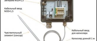
sensors are used to control water and air temperatures.
. On the main panel of the electric boiler control unit there are two marked regulators - “air” and “water”. Each of the regulators has its own graduation with a digital code, which indicates the temperature measured in Celsius. Thanks to such regulators, you can easily set the required thermal values of the coolant. The regulator operates on the principle of adjustment: when the temperature of the electric boiler reaches the values that were set in the options, the heating element will stop heating, and when the values drop below the required level, the heating devices will start working again.
Delta connection
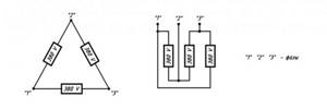
When connecting according to the “triangle” scheme, the leads of the tubular heater are connected in alternate order. A connection diagram of this type means that: pin number 1 of the first heater will be connected to pin number 1 of the second heater; pin No. 2 of the second heating element will be connected to pin No. 2 of the third heater; from the first heater, terminal No. 2 will be connected to terminal No. 1 of the third heating element. If you follow this pattern, you should end up with three arms - “a”, “b”, “c”. Each arm will receive its own phase:
Connection option to a three-phase power supply network type TRIANGLE
Let us consider in the diagram the second option for connecting heating elements to a three-phase network called TRIANGLE.
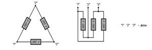
With this option, the heaters are connected to each other in series. As a result, we should have three shoulders for phases A, B and C. For example:
- For phase A - we connect the first terminal of the heating element No. 1 and the first terminal of the heating element No. 2
- For phase B - connect the second terminal of the heating element No. 2 and the second terminal of the heating element No. 3
- For phase C - connect the second terminal of the heating element No. 1 and the first terminal of the heating element No. 3
Now that we have become familiar with the two types of connecting heating elements, we can consider the dependence of the power and temperature of the heaters on the type of connection circuit.
The power of the heaters and their temperature supply depend on the heating element connection diagram
When choosing a heater, the buyer first of all pays attention to its power. Technical practice shows that with a constant connection to a certain network, when transformers are not used, power indicators depend only on the electrical resistance of the resistive element, which is located in the heating device itself. The dependence is defined by the formula:
I is the current flowing through the resistive element.
Due to the fact that the current passing through the spiral depends only on the voltage applied to the ends and the intrinsic electrical resistance (R) of a particular section of the spiral, the formula can be simplified:
From this we can conclude that under constant voltage conditions, power will increase only when the resistance drops.
The electrical resistance of most heating devices directly depends on the temperature output of the heating element itself. But, the resistance will change slightly within a few hundred degrees. It is worth understanding that with silicon carbide heaters the situation will be completely different. Since in them the function of a heating element is performed by a non-metallic rod, the resistance here will not change in a linear order. The resistance of such devices can be in the range of 0.5...5 Ohms, which will not allow direct connection of the heating device to a 220 Volt network, much less 380 Volt. By technical standards, silicon carbide heaters can be connected to a standard network if they are assembled in a daisy chain. But. It is worth noting that this technique is ineffective if it is necessary to accurately control the power and adjust a certain oven temperature. The best way is considered to be connecting electric heaters to the network using laboratory controlled autotransformers or standard statistical electromagnetic devices.
There are heaters that are manufactured directly for a three-phase network, for example, block heating elements or W-shaped silicon carbide heaters. The method of connecting them depends on the calculated voltage in a star or delta circuit. When connecting according to the “triangle” scheme, it means connecting three heating units whose resistances are equal and each will be supplied with a voltage of 380 Volts. The “star” circuit with the presence of a neutral wire is described in detail above and is intended to supply 220 Volts to each consumer.
The neutral wire is necessary to connect consumers with different electrical resistances.
You can get advice on selecting power, operating temperatures and how to connect heaters for free by contacting. Our technologists will help you accurately calculate all the parameters and characteristics of electric heaters for your equipment and will complete your order in a short time. Delivery of industrial heaters "TEN24" is carried out throughout Ukraine.
Source
Dependence of temperature and heating power on the connection diagram option
Heater power is a very important parameter that many buyers focus on when purchasing a heating element. In fact, the power of the heating element depends only on the resistance of the heating coil. Of course, if you do not use transformers and the power from a certain network will be constant. This property of dependence can be easily calculated using a simple formula from a school physics course:
Power (P) = Voltage (U) * Current (I)
In this case, we take the potential difference between the terminals of the electric heating element as the voltage value, and the current strength must be measured that will flow through the heating coil.
The current strength can be calculated using the formula I=U/R, where R is the electrical resistance of the heating coil. Now let’s substitute this value into the power formula, and it turns out that the power of the heating element depends only on voltage and resistance.
Thus, we conclude that at a constant power supply voltage, the power of the electric heater will change only when the resistance changes.
The resistance value of the resistive element in the bulk of heaters is directly dependent on the temperature release value. But in heaters with a nichrome or fechral spiral, for example, within a hundred or two degrees the resistance practically does not change.
In the situation with high-temperature heaters made of silicon carbide or molybdenum disilicide, the picture will be completely different. In high-temperature heaters, as the temperature increases, the resistance drops very significantly, ranging from 5 to 0.5 ohms, which makes them very beneficial in terms of electricity consumption in furnaces.
Mixed method
The combined connection type is applicable for electric motors with a power of 5 kW or more. The star-delta circuit is used when it is necessary to reduce the starting currents of the unit. The principle of operation begins with a star, and after the engine reaches the required speed, it automatically switches to a triangle.
Scheme for starting a three-phase electric motor using a relay
This scheme is not suitable for devices with overloads, as a weak torque occurs, which can lead to breakdown.
Boiler heating element connection diagrams
Option 1. Connection diagram to a single-phase network
Typically, three single heating elements in such a design are placed so that the contacts from different heating elements are located opposite each other.
To connect a heating element to 220 Volts, you need to connect three contacts from different single spirals with a jumper and connect them to the working zero.
The three remaining contacts also need to be connected and connected to the working phase. This will ensure that all heating elements are turned on simultaneously for heating when power is applied.
However, the connection is not made directly this way, and for every second contact the heating element is connected to a phase after its own machine or, what is done more often, it is connected from its own control line (automation).
Option 2. Three-phase connection
If we look at the heating elements for boilers sold, we will see that almost all of them are labeled as 220/380 Volt heating elements.
If you have this version of the heating element, and you have the opportunity to connect to a three-phase power supply of 220 Volts or 380 Volts, then you need to use connection diagrams called “star” and “delta”.
According to the “star” circuit of 220 Volts, three phases, you need to connect the three contacts of single heating elements with a perm and connect them to the working zero. Apply to the second free contacts via a phase wire. Each single heating element will operate from 220 Volts, independently of each other.
According to the “triangle” circuit of 380 Volts, you need to connect contacts 1-6, 2-3, 4-5 with jumpers, for single heating elements 1-2.3-4.5-6 and supply phase wires to them. Each single heating element will operate at 380 Volts, independently of each other.
Theory
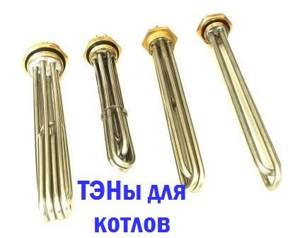
What is a heating element in an electric boiler?
From the point of view of electrical engineering, this is an active resistance that generates heat when an electric current passes through it. In appearance, a single heating element looks like a bent or curled tube. Spirals can be of very different shapes, but the connection principle is the same; a single heating element has two contacts for connection.
When connecting a single heating element to the supply voltage, we simply need to connect its terminals to the power supply. If the heating element is designed for 220 Volts, then we connect it to the phase and working zero. If the heating element is 380 Volt, then connect the heating element to two phases.
But this is a single heating element, which we can see in an electric kettle, but not in an electric boiler. The heating element of a heating boiler is three single heating elements mounted on a single platform (flange) with contacts located on it.
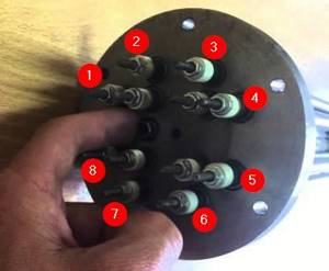
The most common boiler heating element consists of three single heating elements mounted on a common flange. On the flange there are 6 (six) contacts of the electric heating element of the boiler for connection. There are boilers with a large number of single heating elements, for example, like this:
Electrical installation in a three-phase network
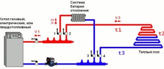
The diagram for connecting an electric boiler to a three-phase network is more complex, but even a beginner can do it.
The three phases must be connected as follows:
Please pay attention to the following nuances:
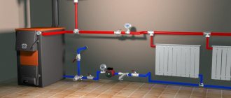
For your attention, a visual project of electric heating in a two-story dacha using a boiler:
The optimal source of energy for heating the evaporation tank is a residential electrical network with a voltage of 220 V. You can simply use a household electric stove for these purposes. But, when heating on an electric stove, a lot of energy is spent on useless heating of the stove itself, and is also radiated into the external environment from the heating element, without doing any useful work. This wasted energy can reach decent values - up to 30-50% of the total power expended on heating the cube. Therefore, the use of conventional electric stoves is irrational from an economic point of view. After all, for every extra kilowatt of energy you have to pay. It is most effective to use elec- tronics embedded in the evaporation tank. Heating elements. With this design, all energy is spent only on heating the cube + radiation from its walls to the outside. The walls of the cube must be thermally insulated to reduce heat loss. After all, the cost of heat radiation from the walls of the cube itself can also amount to 20 percent or more of the total power expended, depending on its size. For use as heating elements embedded in a container, heating elements from household electric kettles or other suitable sizes are quite suitable. The power of such heating elements varies. The most commonly used heating elements with a power stamped on the body are 1.0 kW and 1.25 kW. But there are others.
Therefore, the power of the 1st heating element may not correspond to the parameters for heating the cube and may be more or less. In such cases, to obtain the required heating power, you can use several heating elements connected in series or series-parallel. By switching various combinations of connecting heating elements, a switch from a household electric. plates, you can get different power. For example, having eight embedded heating elements, 1.25 kW each, depending on the switching combination, you can get the following power.
Star connections.
For example, let’s imagine a “star” circuit, which is made up of three electric heaters.
The second output (2) of each of the heaters is supplied with the corresponding phase. The first terminals (1) of the heating elements are connected together with the simultaneous formation of a common point, which is called zero or neutral. This type of load connection is a three-wire one.
a three-wire connection at an operating voltage of 380 Volts. Below we propose to consider the installation diagram of a three-wire connection of heating elements into a three-phase electrical network. In this case, the supply and shutdown of voltage occurs thanks to three-pole circuit breakers.
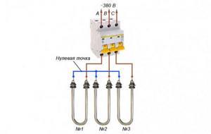
In the presented diagram it can be seen that the terminals located on the right side of the electric heaters are connected to phases A, B and C, and the terminals located on the left are connected at the zero point. Between the terminals on the right and the zero point, the operating voltage is 220 Volts.
In addition to the described circuit, you can also use a four-wire one . When connecting using a four-wire circuit, it is assumed that a three-phase load with a voltage of 220 Volts is connected to the network. In this case, the inclusion of the zero point of the load is connected to the zero point of the power source.
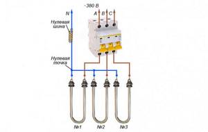
In the diagram presented above, the right terminals of the tubular electric heaters are connected to the corresponding phases, and the left ones are closed at one point, which is connected to the zero bus of the power source. Between the zero point and the terminals of the electric heaters, the voltage will be 220 Volts.
If it is necessary to completely disconnect the load from the mains, automatic switches “3+N” or “3P+N” . Such machines turn on and off all available power contacts.
Laws that apply when connecting star-type heaters:
Connection using a switch
To ensure reliable operation of heating elements in the electrical network of a house or apartment, it is better to install an automatic machine in the house panel - it can be connected directly next to the device. The most optimal option is to install a two-pole switch: if it deviates from the operating parameters, it immediately turns off the phase and neutral, as a result of which the heating element is completely disconnected from the power supply.
If the house is grounded, it is necessary to prevent electric shock if the insulation is damaged. To do this, it is recommended to connect the heating element through an RCD or automatic circuit breaker. Such protection will work according to the following scheme: if the insulation is broken, then a phase is supplied to the housing, which, according to the principle of least resistance, will go along the grounding conductor. The automatic device will react and turn off the current supply to the device. Also, if there is a short circuit, the machine will turn off to prevent a fire.