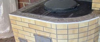
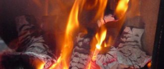
The stove has long been considered a multifunctional appliance. In almost every country house or dacha you can see a stove device. The stove is used to heat the home, cook food on it , and bake bakery products. Today, progress has reached the point that you can have your own bakery at home. Let's take a closer look at the features of all devices that are used for baking bread , and also study the construction of a fireplace oven with a bakery with your own hands.
Furnace design
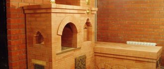
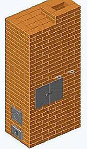
The design of the stove is based on the fireplace-bread oven scheme described by the Finnish author J. Keppo in the book Brick stoves and fireplaces: masonry (St. Petersburg: Alpha-mer Publishing. 2005). Design changes were made to this scheme based on the developments of Igor Kuznetsov: dry slots, a catalyst grille and an air duct system for supplying secondary air were made.
In addition, the massive fireplace tooth was removed from the Finnish design, instead of which we now have a catalyst grate in the hearth of the bread chamber. The gas flow pattern in the furnace is as follows. Hot gases, rising upward during the combustion of wood, pass through the catalyst plates, enter the bread chamber and heat it. Further gases flow depending on the selected combustion mode. In the fireplace mode (with the rotary valve open), the gases go directly into the pipe, and when the rotary valve is closed, they are divided into two streams on the ceiling of the bread chamber and, through channels located on the sides of the oven, are lowered DOWN to the level of the second row. Here they gather in one ascending channel and rise up to the pipe. Dry slots cut the firebox in the rear corners and, according to the concept of free movement of gases in the furnace, allow cold air that is not involved in the combustion process to go into the lower parts of the side descending channels, which increases the temperature in the firebox. In addition, thanks to this device, the furnace becomes truly slag-free, since the draft effect (blowing out the furnace with the valve not tightly closed) does not affect the hot gases in its upper part and it retains heat longer. Well. finally, these slots contribute to more uniform heating of the furnace, since through them some of the hot gases enter the side channels directly from the firebox and the temperature of the lower part of the furnace rises as a result.
The secondary air supply channels begin with holes in the ash chamber, pass between the bricks of the combustion chamber lining and end with holes in the upper part of the firebox under the combustion grate.
Do-it-yourself Kuznetsov stoves ordering
Igor Viktorovich Kuznetsov is a well-known Russian engineer-inventor who has been developing new models of furnaces and their constant improvement since 1962. During this considerable time, more than 150 different models have appeared, thoroughly tested in practice and have earned the widest demand among the owners of private houses. The designs of this inventor are distinguished not only by their effective work in heating residential buildings, but also by the ability to add comfort and originality to the interior of the premises.
Do-it-yourself Kuznetsov stoves ordering
It is not so easy to build Kuznetsov stoves with your own hands, the order of which, I must say, is quite complicated. However, if you want to save a decent amount, and also if you have certain skills and the ability to read the relevant diagrams, this is quite possible. Therefore, if you decide to carry out this work yourself, you need not only to choose a suitable structure, but also to very carefully study its order and recommendations for laying.
Design features of I.V. Kuznetsova
Judging by the design features of the heating devices, the engineer, when carrying out his developments, set himself two goals - the efficiency and productivity of the stoves. That is why the inventor pays great attention to the arrangement of the internal channels of the furnace, through which there is intense movement of combustion products along with the air heated in the furnace. Working on designs, the master in each of his models tries to achieve a longer retention of the heated gas mass inside the furnace structure, which helps save fuel while maintaining heat for a long time.
These characteristics correspond to stoves called “bell-shaped”, that is, they have special chambers for retaining heat. Typically, Kuznetsov’s designs have two “hoods” - the lower one, combined with the combustion chamber, and the one located in the upper part of the furnace. The operating principle of the lower “hood” is to separate the generated gases into hot and cold. Thus, combustion products, rising to the ceiling of the hood, are retained and accumulate heat, while in many structures the heated air does not encounter any special obstacles to exit into the chimney.
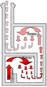
The principle of operation of two “hoods”
Gases are also retained in the upper “cap” because the exit from it is located at its base. Thus, before entering the chimney, hot gas flows rise to the ceiling, heating the entire chamber.
Thanks to this system, the internal temperature of the furnace increases significantly and is maintained for a long time, which gives a high efficiency of the heating device, reaching up to 95%. The difference can be seen if we compare this parameter, for example, with the efficiency of a Russian traditional stove, which, alas, is only 45÷50%.
In addition to rational air movement, the conservation of thermal energy is also facilitated by valves installed in the right places, which can also delay or redirect the movement of gases as necessary. These elements are also able to regulate heat circulation. So, when the “summer” valve is opened, the stove will be set only to cooking, because the heated air will go into the chimney along the path of least resistance, heating only the firebox and hob, without getting into the upper bell part of the structure.
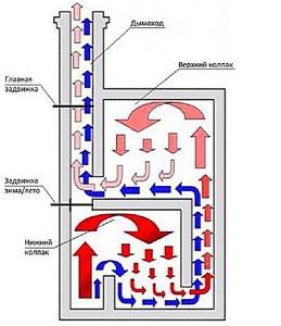
Such a stove can operate in two modes: “summer” and “winter”
Thanks to such a working furnace system, one can highlight a number of advantages of the designs developed by I.V. Kuznetsov:
- The oven warms up and releases heat naturally and evenly.
- It becomes possible to allocate more space for installing a heating element - a hob.
- Combustion occurs without the formation of soot and smoke, since combustion products are almost completely destroyed.
- Heat losses are reduced to a minimum.
- Due to the uniform heating of the structure, there is almost no deformation of the masonry and the formation of cracks in the seams.
- This internal design allows you to create various shapes of stoves and with a variety of designs.
- In addition, furnaces developed by I.V. Kuznetsov, can be equipped with a water circuit or a built-in heating tank, which will provide hot water supply in the house or even water heating of other rooms.
You can equip the Kuznetsov stove with a water circuit for a local heating system
When using the operating principle of such a stove design, it becomes possible to create various household stoves, depending on their purpose:
- A heating type of stove designed only for efficient heating of a residential one-story or two-story building.
- Cooking ovens designed primarily for high-quality and quick cooking.
- Sauna stove options - for efficient heating of sauna rooms.
- Outdoor oven-barbecue complexes, with grills and smokehouses.
- Fireplace stoves, which are intended not only for basic heating, but also for creating a cozy environment and an aesthetically attractive interior in the house.
- If desired, you can create multifunctional versions of stoves, including heating, cooking and aesthetic functions.
How to fold an I.V. oven Kuznetsova
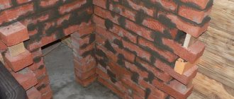
The construction of a real brick oven is always a rather labor-intensive and complex process that requires certain knowledge, technological skills, and possession of certain secrets of craftsmanship. Therefore, in order to get a high-quality heating device, you need to gain some experience in this work in advance. Masters who have been practicing this art, without exaggeration, for a long time, advise novice stove makers to carry out preliminary masonry work before major masonry - without mortar, that is, dry.
The construction of any brick kiln is a rather complex and labor-intensive process.
In addition, if you are laying out your first oven, you should not experiment, trying to add your own innovations to the already established order. In this case, it is recommended to strictly adhere to the chosen scheme and carry it out without any deviations. Therefore, you should immediately decide on the functions that the stove should perform. Since, I.V. Kuznetsov developed and compiled more than 150 designs, from which you can always choose the appropriate option.
If the construction of a stove is planned at the stage of building a house, then its installation should be designed in such a way that it heats two or even three rooms at once.
It is more difficult to build stoves into an already built house, since you will have to make precise calculations to remove part of the wall. In this case, wall-mounted options are usually chosen, but they are capable of efficiently heating only one room. However, if desired, it is possible to solve any problem, of course, taking into account the location of the floor beams and load-bearing walls.
If desired, a brick stove can be built into an interior wall
It is important to protect flammable surfaces from overheating, therefore, if the stove is installed in a wooden building, then at the junctions of the walls of the house and the stove it is necessary to make gaskets from non-combustible material, for example, asbestos.
In addition, at the joints of structures, gaps filled with such material are also necessary for the free expansion of the brickwork when it is heated, otherwise the mortar in the seams may become covered with cracks, and the structure of the furnace itself may undergo deformation.
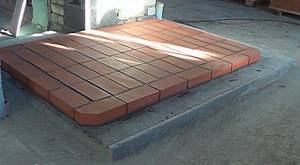
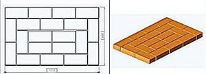
It is very important to arrange a high-quality foundation for the furnace structure. It is usually made of concrete with waterproofing. The foundation of the furnace should not be connected to the foundation of the main building, since they will shrink differently and should not “pull” each other along with them.
The linear dimensions of the concrete foundation must be larger than the dimensions of the furnace base by at least 100 mm on each side of the structure. The depth of the foundation is calculated depending on the massiveness of the furnace structure and the composition of the soil on which the construction is carried out. On average, the depth of the excavation pit for the foundation varies from 400 to 600 mm, and a waterproofing sand cushion and a reinforcing layer of crushed stone are necessarily laid at the bottom. Well, the side walls are formed by installing wooden formwork.
The process of arranging the foundation is quite labor-intensive, however, it must be carried out in full and with high quality, since the accuracy and durability of the entire furnace structure will depend on its reliability and smooth surface. You should never rush into construction - the poured concrete foundation must be given at least a month to fully mature and harden.
Moving on to further work, when laying the stove you need to take into account the following points:
- Before laying the first row, one or two layers of waterproofing material - roofing material - are laid on the foundation, which is further recommended to be marked with chalk according to the size of the stove base. This will make it easier to lay the first row.
A brick stove will definitely require a reliable foundation
- If the furnace masonry work is planned to be made of red brick, then it is recommended to line the combustion chamber with fire-resistant fireclay material. It retains heat longer and is resistant to high temperatures.
- It is very important to maintain thermal gaps of 5 mm between fireclay and red bricks - their coefficient of linear expansion differs significantly, and the material must be allowed to expand freely when heated.
- It is recommended, after raising each successive two rows, to reinforce the furnace wall with wire, which is laid in a seam along the entire length of the row.
- Cast iron and steel elements that will come into contact with open fire are wrapped around the perimeter with asbestos rope or fragments cut from a single sheet. This material will not only protect the metal from burning, but will also create the necessary gap for thermal expansion.
- The folded oven must be dried for a long time before use. To do this, all doors and valves are opened for free air circulation throughout all departments of the structure. Drying is often done by installing a regular incandescent light bulb with a power of 200÷400 W in the firebox. The heat given off by the light bulb and the through air movement created from this will contribute to faster drying of the structure.
- The dry stove is first heated with a small amount of fuel, the flame from which will harden the walls of the combustion chamber with fire.
- If you plan to carry out external finishing of the building, then it should be done after at least one season of operation of the heating device, when the folded stove will shrink almost completely.
You may be interested in information about what a fireplace stove with a water heating circuit is
Order diagram and materials for construction
The order is the scheme that is developed for each furnace. This graphical plan shows in detail the configuration and quantity of materials for each row. Before starting work, you need to carefully understand the order scheme, and if it is not clear, then you should seek clarification from a specialist. As a rule, it is quite easy for a technically savvy person to understand the order drawings, especially since they are usually accompanied by a detailed description.
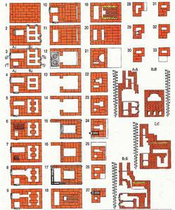
This is what the flowchart usually looks like
The sequence diagram should look something like this. The best option is if the arrangement diagram contains several more options for sections of the furnace - this will help to see the internal structure of the structure and will greatly facilitate the work.
In different sections of the furnaces, both whole bricks and hewn or chipped bricks can be used into several equal parts. In some cases, the brick can even be divided into 8 parts, and ⅛, ⅜, ¼ bricks, etc. are used to form some sections of the kiln. The use of these parts is always indicated on the order diagram.
In addition, you need to know that some bricks will need to be cut out to install metal elements, such as a hob or valve. In some cases, you will have to trim or cut the brick at a certain angle, which is also shown in the order.
Each specific model requires a certain amount of material, which can be calculated independently based on the order, or the list is attached to it in ready-made form.
To build any furnace you will need to purchase the following materials:
- For the internal masonry of the firebox, it is recommended to prepare fireclay bricks (ША-8). If it is not available, then you can replace it with another refractory brick.
- For the main masonry of the building, you will need ordinary ceramic bricks with a strength grade of at least M150.
- The solution will require one or two types of clay, one of which must be refractory and ductile. This material will require 100÷150 kilograms, depending on the massiveness of the structure.
- In addition to clay, the solution will require sifted sand. Its volume should exceed the amount of clay by 2÷2.5 times. In total, for a masonry consisting of 500 bricks, it is necessary to prepare 0.2 cubic meters. m. clay-sand mixture. However, many modern stove makers have already managed to evaluate ready-made masonry mixtures for stoves, which can be purchased at a specialized store.
- Metal and cast iron structural elements are selected individually for each model. The amount of wire for reinforcing the rows will also depend on the choice of oven model and its perimeter.
Prices for ceramic bricks of strength grade M150
ceramic brick m150
Detailed order of the Kuznetsov heating and cooking furnace OVIK-9
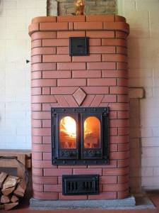
The heating and cooking furnace presented below is designed based on the OVIK-9 model, developed by engineer V.I. Kuznetsov. The only difference between these structures is the relative position of the combustion and blower doors, but otherwise the structures are completely identical.
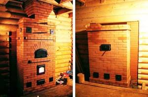
Heating and cooking furnace based on the development of I.V. Kuznetsova OVIK-9
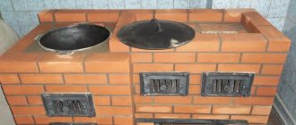
This version of the stove is designed both for heating the house and for cooking, so it is quite suitable for installation in any country private houses.
For cooking, the model has a cooking chamber with a two-burner stove and lockable metal doors. It is equipped with its own exhaust duct with a valve, with which you can regulate the temperature inside the closed niche. Due to the fact that the chamber can be completely closed, it can serve as an oven, so brackets for installing baking sheets are often built into its walls.
If it is necessary to quickly heat the premises, the cabinet doors are left open, but even in this case, food can be cooked on the hob itself.
The stove has a two-bell design, so it can operate in two modes - “summer” and “winter”, that is, it can be lit only for cooking in the summer or heating the house and cooking in the winter.
The depth of the fuel chamber is 450÷470 mm and has a “dry” seam for free expansion of the material when heated. If desired, the dimensions of the combustion chamber can be increased to 510÷530 mm - for this, the rear wall of the firebox will need to be laid out not in half a brick, as indicated in the order, but in a quarter of a brick. However, in this case, it is not recommended to use a “dry” joint, since the wall will be unstable and the bricks in it may be displaced when laying firewood.
Such a stove has dimensions of 1015×630×2100 mm, has a heat output of 3600 W, provided it is fired twice. It is quite capable of heating a room or adjacent rooms with an area of 30÷35 m².
Necessary materials
For the construction of this heating structure, the following materials will be required (excluding the construction of the pipe and the arrangement of the foundation):
- red brick – 430 pcs.;
- fireclay refractory brick (ША-8) for the firebox – 22 pcs.;
- combustion door (DT-3) 210×250 mm – 1 pc.;
- blower door (DPK) 140×250 mm – 1 pc.;
- grate 250×252 mm – 1 pc.;
- two-burner cast iron hob 586×336 mm – 1 pc.;
- cooking chamber doors 510×340 mm – 2 pcs.;
- valve for the cooking chamber 130×130 mm – 1 pc.;
- valve for “summer” operating mode 130×130 mm – 1 pc.;
- chimney damper 130×250 mm – 1 pc.;
- steel corner 36×36×4×600 mm – 4 pcs.;
- steel strip 40×4×600 mm – 1 pc.;
- steel sheet 600×550×3 mm – 1 pc.;
- steel pre-furnace sheet 500×700×3 mm – 1 pc. It can be replaced with another heat-resistant material, such as ceramic tiles.
Prices for fireclay refractory bricks (ША-8)
Fireclay refractory brick sha-8
Furnace construction process
| Illustration with the order of the furnace masonry | Brief description of masonry operations |
| The first row is completely solid, since it is the basis for the rest of the order, so it must be laid out with precise observance of the horizontal masonry and with perfectly aligned right angles. The diagram shows standard dimensions, and they can be slightly changed, since the parameters of the brick and the thickness of the seams between them may vary slightly. As a rule, the thickness of the seams is usually taken to be 5 mm, but it should be taken into account that the corners of the remaining rows of masonry should ideally coincide with the base. Therefore, they need to be measured using a construction angle, and then compare the dimensions of the diagonals of the resulting rectangle - they must be equal to each other. This row will require 20 red bricks. |
| On the second row, the formation of the ash chamber and the lower furnace hood begins. Since the base of the cap will need to be cleaned after completion of the masonry, two halves of bricks are installed, which protrude outward from the common row. During cleaning, these elements are removed from the wall, which allows this process to be carried out without problems. When laying the second row, these bricks are not fixed to the mortar - this will be done after the stove is completely erected and cleared of fallen mortar and other construction debris. A blower door is installed on the same row, which can be temporarily supported with stacks of bricks for stability. This row uses 14 red bricks. | |
| The third row is laid out according to the diagram. In the process of laying it, the blower door is tightly fixed to it. | |
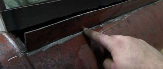
| The fourth row is partially laid out from fireclay refractory bricks - the side and rear walls of the fuel chamber are formed from it. The door of the ash chamber is covered with two red bricks, which extend above it and are cut at an angle. In the same way, two hewn refractory bricks are placed on the back side of the blower door. A thermal gap of 5 mm is left between the red and fireclay bricks. To fulfill this condition, the craftsmen use a little trick, and instead of mortar, they place ordinary packaging corrugated cardboard, which has the required thickness, between these types of bricks. After it burns out, a perfectly even thermal gap remains. Such gaps should also be provided in subsequent rows where red and fireclay bricks are joined. For this row you need to prepare 11½ red and 3½ fireclay bricks. | |
| The fourth row continues. After laying the side bricks above the blower door, the middle of the door is covered with fireclay and ceramic bricks, hewn on the sides on both sides; this masonry system is called a “castle”. To do this you will need 1 red and 1 fireclay brick. | |
| On the fifth row, a fuel chamber is formed. The fireclay brick installed on the front wall of the firebox is cut obliquely. The space inside the firebox between the fireclay bricks must correspond to the size of the grate, since it must fit freely into the rectangle formed by the bricks, on the bricks of the lower 4th row protruding by 10÷15 mm. At the same time, it is necessary to leave a thermal gap of 5 mm between the side walls of refractory bricks and the grate, which will allow the metal to expand without problems when heated. In the space behind the firebox, where the lower hood of the furnace is located, a separate vertical channel is formed, the size of half a brick. This channel will connect the lower and upper furnace hoods. The number of bricks used in this row is 12 ½ red and 4 fireclay. | |
| On the fifth row, without mortar, a grate is laid on the protruding bricks of the 4th row. The five-millimeter gaps between the brick and the grating are filled with sand. | |
| Sixth row. At this stage the fuel door is installed. There should be a gap of 5 mm between the walls of its frame and the adjacent bricks, which is filled with non-combustible material. To do this, most often the frame is wrapped with rope or pieces of asbestos. To lay this row, you need to prepare 12 red and 3 fireclay bricks. | |
| Seventh row. When laying the back wall of the fuel chamber in this row, a gap of 20÷30 mm is left on the left edge of the brick - this will be the “dry” seam. It is necessary to remove unburnt gases from the furnace and create conditions for more intense combustion of the flame. This row will require 12 red and 3 fireclay bricks. | |
| Eighth row. The masonry is carried out strictly according to the scheme using 12 red and 3 fireclay bricks. | |
| Ninth row. The walls of the combustion chamber are removed, and a passage is formed between it and the lower hood to remove combustion products. The fireclay side walls of the firebox should be 10 mm lower than the rest of the row (these walls are highlighted in lilac in the diagram). The fireclay and red bricks placed above the fire door are moved slightly to cover part of its frame. These bricks are first cut diagonally and thus form a kind of “bowl” into which the central brick will be laid. For a row, 12 red and 2½ fireclay bricks are used. | |
| On the ninth row, between the front side bricks above the door, a central brick covering the frame of the combustion door is placed, previously hewn obliquely on both sides at the same angle as the side ones, forming a “bowl”. The left side wall of the fireclay brick firebox is covered with an asbestos strip 10 mm thick, which will equalize this side with the height of the entire row. | |
| Tenth row. In this row, red brick is laid dry on fireclay bricks covered with asbestos, that is, without mortar. In the red brick framing the firebox, a small cutout approximately 10 mm in size is made, on which the hob will be laid. Moreover, between the slab and the walls of the brick on all sides there must be a gap of 5 mm for the expansion of the metal when it is heated. The refractory bricks installed on the front and right side of the fuel chamber are cut at an angle - they are shown in orange in the diagram. At the same time, it is necessary to ensure that there is a gap of 10 mm between the fireclay bricks and the hob. This row will require 14½ red and 1½ fireclay bricks. | |
| After completing the previous work on laying the 10th row, asbestos rope impregnated with clay mortar is distributed onto the cutouts in the laid bricks. The hob is laid on top of the asbestos layer. The gaps between the slab and bricks are filled with sand. If you purchased a panel that has stiffening ribs on the reverse side, then additional cutouts are made for them. The hob should lie only on its edges, but not on the stiffeners, and be “recessed” relative to the surface of the entire row by 5 mm. | |
| 11th row. From this row, the walls of the cooking chamber begin to form and a frame with doors is installed. Moreover, it must be taken into account that a five-millimeter gap must be maintained between the metal frame and the bricks. To make it easier to form, it is recommended to wrap the frame with asbestos rope. For the 11th row you will need 11 red bricks. | |
| The 12th row is laid out according to the pattern, and 11 red bricks are used for it. | |
| 13th row. The formation of the cooking chamber and vertical side channels continues. | |
| 14th row - work proceeds strictly according to this scheme. | |
| The 15th row is placed in two stages. The first step is to raise the walls of the cooking chamber and vertical channels to the level of the metal door frame. | |
| Next, it is necessary to arrange the overlap of the cooking chamber. To do this, a 600x550 mm steel sheet is laid on the 15th row masonry, in which a cutout is made for the exhaust duct. The metal sheet is necessary so that the ceiling of the cooking chamber is cleaner, and during cooking, various debris in the form of mortar from masonry joints does not fall on top of the food. For rigidity, four metal corners and a steel strip are installed on top of the sheet. | |
| 16th row. Red brick is laid on the metal corners and strip - the order is shown in the diagram. Only the openings of the vertical channels are left open. Before laying, on the bricks framing the nearest vertical and exhaust ducts, cutouts are made for installing chimney dampers. The valves will ensure the “summer” operation of the furnace and, if necessary, the tightness of the cooking chamber. The cutouts are made in such a way that there is a gap of 5 mm between the brickwork and the valve. In this row the masonry consists of 20 red bricks. | |
| On the 16th row, two valves are installed on prepared platforms with cutouts. | |
| On the 17th row, the cooking chamber and installed valves are covered with red brick, so that the smoke exhaust channels remain open. For masonry you need to prepare 19 red bricks. | |
| On the 18th row, the formation of the upper cap of the structure takes place. To do this, two half-bricks are installed dry, which rise above the main masonry - they are necessary to clean the base of the cap. These bricks are fixed to the mortar after the laying of the stove is completed and the base is cleared of mortar and debris. The row uses 13½ red bricks. | |
| The 19th row is laid according to the pattern using 12½ red bricks. | |
| The 20th row is also laid out according to the pattern and will require 13½ red bricks | |
| 21st row. The masonry is carried out according to the presented scheme, and 14 bricks are used for it. | |
| Next, a rather long section of the building is laid out according to a single pattern, only with alternating even and odd rows. 22nd, 24th and 26th rows. The work is carried out according to the same pattern, the rows consist of 14 bricks. | |
| The 23rd and 25th rows are also laid out according to the general pattern and also consist of 14 bricks. | |
| 27th row. In this case, 14 bricks are also used, but the configuration of their arrangement is somewhat different from the previous rows, since they prepare the basis for subsequent almost continuous rows. | |
| On the 28th row, cutouts are made in the bricks framing the chimney channel to install the main chimney valve. In the diagram, the cutout locations, to a depth of 10 mm, are highlighted in lilac. When making cuts, you need to periodically try on the valve itself, since it should be at a distance of 5 mm from the brick walls, that is, it should fit freely into the cut gap. | |
| On the same row, the valve itself is installed in the cutout on the solution. | |
| For the 29th row, 19 red bricks will be required, since the surface of the structure is almost completely covered. Only the chimney opening with the damper already installed remains open. | |
| The 30th row covers almost the entire surface for the second time. It also requires 19 bricks. | |
| 31st row - the base of the mounted pipe is laid with a cross-section of the chimney opening, the size of one brick. Consists of a row of 5 bricks. | |
| Next, the chimney itself is formed. For each of the rows, when laying it out, you will also need 5 red bricks. |
Detailed instructions and diagrams will help you lift this fairly compact stove model yourself. To make it look more elegant and neat, it is recommended to buy rounded shaped bricks for laying the corners or process them yourself. So, in addition to accuracy, the oven will also gain greater safety. This is especially important to provide for in cases where there are small children in the house.
If the order diagram is disassembled and understandable, then build a furnace designed by I.V. Kuznetsov will be quite simple. A correctly selected model is quite capable of decorating an interior made in any style. To make it neat and aesthetic, you shouldn’t rush - it’s better to do all the work measuredly, calculating each step and strictly following the attached diagram. Read about automatic coal-fired boilers on our website.
And at the end of the publication - a video about the laying of another heating and cooking furnace designed by I.V. Kuznetsova:
Video: Kuznetsov heating and cooking stove OVIK-4
Brick selection
What type of stove will turn out depends largely on the source materials and, first of all, on the brick from which the stove will be built. Each type of brick has its own characteristics that must be taken into account and which should be known. The quantity of each grade of brick becomes clear from the order of the kiln and the total height of the chimney, taking into account the interfloor cutting, the “otter” and the distance from the chimney to the roof ridge. You need to buy bricks with some reserve for the battle (about 5-7%). I used 5 types of bricks in this kiln. Lode bricks are produced in Lithuania by JSC LODE, the largest manufacturer of ceramic building materials in the Baltic countries. Products under this brand are distinguished by high quality, clear geometric shapes, and original colors. Therefore, I laid out the outer walls from it. At the same time, I used two types of red solid brick - rectangular and with a Rounded (R60) corner.
These bricks have features: the rectangular one has a barely noticeable convexity on the front side, and the corner one has convexities on the curves. This has to be taken into account during laying. In addition, the Lode bricks have chamfers on the edges of the front sides, as a result of which the usual seam (about 5 mm) seems much thicker, and the chamfer of the corner brick in its rounded part is slightly less than the longitudinal one. Stoves made from this brick look great, but its high cost is often an argument in favor of a cheaper one - Vitebsk. Vitebsk brick. I used red solid Vitebsk brick (often called stove brick) to lay the inside of the stove (chimneys and ash chamber). This brick is produced in Vitebsk by JSC Keramika in two workshops: workshop No. 1 and No. 2. The brick from the first workshop is marked in the form of tattoos and, according to my Moscow colleagues (as well as my own), is of higher quality than the brick from the second workshop. The latter is marked with a flat stamp indicating the workshop number
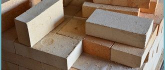
Vitebsk brick may have deviations from standard sizes of 2-3 mm. In order not to encounter uneven seams (both horizontal and vertical) during laying, it is better to adhere to the well-known rule: select a brick for each row in advance. It is not recommended to build a pipe higher than the roof from this brick - it has low frost resistance and after a few years the pipe begins to collapse. Fireclay brick ShchA-8_or ShB 5; They are used, as a rule, for lining fireboxes, although quite often the entire stove or fireplace is made from it, using in some places or completely decorative treatment to resemble wild stone. Produced by several factories. When purchasing, you need to pay attention to the appearance; the brick must have sharp edges, appropriate markings and must not crumble. There is also a sha-5 brick on sale, which is slightly smaller in size and less convenient to work with.
Pipe brick This is a semi-dry pressed ceramic red solid brick with 6 protrusions on one bed. It is produced at the Obolsky ceramic plant in the Republic of Belarus. It has an attractive appearance and strictly maintained dimensions, but is very hygroscopic. Before using this brick, it must be thoroughly soaked in water. One of the main advantages is a very smooth surface (and the back and front edges do not differ in quality and the surface of the chimneys turns out to be very smooth). In this regard, working with this brick is a pleasure. But it is not recommended to use it in hot places in the furnace and when building a pipe above the roof. This brick was used to build a pipe up to the roof near my stove. Facing - red or yellow slotted ceramic bricks withstand low temperatures when wet. In addition, it is much lighter than other bricks, which is very important when lifting it onto the roof. I used it to lay pipes above the roof.
Row-based masonry of a fireplace stove with a bread maker
Viewers of videos from my YouTube channel often ask me for convenient arrangements that they can print out and take with them to the site, since the description of the masonry in the video cannot always be viewed at the site due to lack of Internet or a dead battery. It is for this reason that here I am laying out the order of the rows of this oven as well as all the others.
osnovaremonta.ru
osnovaremonta.ru
osnovaremonta.ru
osnovaremonta.ru
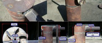
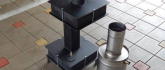
Furnace appliances
Installation of furnace appliances. I secured the cleaning and blower doors in the masonry using soft wire 01-1.2 mm. twisted in four (photo I). First I twisted wire 1 in half using a screwdriver with a hook attachment.
I did it this way: I bent the workpiece in the middle and at this point I hooked it to the hook on the screwdriver. A gloved assistant held the two opposite ends of the wire tightly, pulling them tight. and I turned on the screwdriver. The tension force adjusts the twist pitch. If there was no assistant, I usually made two more hooks and secured them in the wall or on some kind of support. The opposite ends of the wire were hooked and twisted. I inserted the prepared twisted wire into the door mounting holes and twisted it in half again, but this time by hand. The door shelves were coated with a thin layer of masonry mortar and covered with a strip of basalt cardboard. The ends of the strip were connected at the bottom of the shelf. In this case, the strip does not spread to the sides. After this, I cut off the excess part of the wire, bent its end and secured it in a vertical seam with tension. If necessary, using a short nail driven into the seam closer to the door, I pulled the wire away from the edge of the bricks so that it lay entirely in the masonry.
I usually attach Finnish furnace doors with screws, but first fix them with wire. I do it like this. After aligning the door with the center of the front wall of the stove and the horizon with wire passed through the lower and upper side holes in the frame, I attach the door to the board, which is inserted at both ends into dry cracks located in the far corners of the combustion chamber. I select the length of the board so that the board can be easily removed at the end of the laying (photo 2,3).
In our case, at the customer’s insistence, I reinforced the door opening lintel with a 50x50 mm metal corner. placed on the back side of the slab bricks in level with the slab (photo 4). The corner was covered on all sides with basalt cardboard. After the opening was lined and blocked, I finally secured the door with 26 mm screws with a key head, with preliminary drilling of holes for them in the bricks located along the side walls of the opening. I filled the holes with a small amount of masonry mortar, wrapped the screws themselves with asbestos thread and screwed them into the holes. To prevent the thread from flying off the screws, it was lightly coated with a solution. An equally important and difficult moment is the installation of the bread chamber door and the rotary valve. Photo 5 clearly shows a board with a cross, to which the bread chamber door is temporarily attached using the same wire; the cross prevents the board from falling down. The transverse wire twist allows the door to be tightly pressed to the brickwork. The body of the rotary valve at the junction with the brick was carefully insulated with basalt cardboard.
I installed the rotary valve perpendicular to the side wall of the furnace and, according to the instructions, slightly at an angle, on the bricks prepared in advance. I cut a groove in the brick that secures the rod with the rotary handle. It is very important to adjust the location of the rod to the seam of the next row. This greatly simplifies the work. Before installing the valve, I temporarily crushed the stem by slightly loosening the two screws that secure it. I measured the required length of the rod and cut it according to the dimensions of the stove. The rod passes through the masonry inside the tube. Before putting this tube on the rod, I wrapped it tightly with asbestos thread so that the tube was put on with force. The tube itself was also cut to size and wrapped with basalt cardboard. The rod passed through the valve body and fixed the rotary plate on it. I secured the handle to the stem together with the decorative trim later using two screws. The body of the rotary valve in the places where it abuts the brick was carefully insulated with basalt cardboard. Photo 6 clearly shows the installed rotary valve. Under the row of flue covers, I installed a retractable furnace valve, which is the main one (photo 7). It is securely hidden in a basalt coat to protect it from overheating when the stove is operating in fireplace mode.
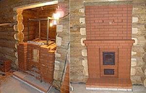
Construction of a traditional oven
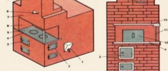
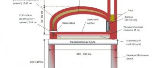
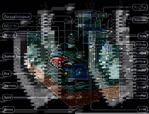
We will not describe the history of the Russian stove and its role in a village house - the topic is widely covered in fiction and technical literature. Let's get straight to the point - let's briefly analyze the traditional design shown in the figure below:
- The lower part of the structure - the guardianship - was built of stone or wood - cedar, larch. The walls of the base form a niche - a stove where firewood was dried and household utensils were stored.
- On top of the guardianship, the first arched vault and a large firebox of the furnace - the crucible - were built. Under and the second arched vault was made with a slope towards the brow - the front part of the structure.
- A roof was placed over the furnace, where the bed was located. The cavity between the second arch of the firebox and the ceiling was filled with sand to increase the heat capacity.
- In front of the mouth of the furnace, a special niche was provided - a bend, ending at the top with a hail (smoke collector) and the chimney itself. The horizontal shelf at the bottom of the opening—the shelf—has a semicircular window facing outward.
- Stoves were installed in the side walls of the brick heater - small niches for drying clothes and other things. The chimney was equipped with a valve and a view located above the heil.
A real Russian stove is fundamentally different from other brick heating structures in the following ways:
- deep vaulted firebox made with a forward slope;
- the chimney is located in the front - in the center or in the corner of the building;
- An indispensable attribute is a bench located above the fuel chamber.
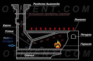
Now let’s look at the operating principle of the stove, shown in the diagram:
- The firewood is placed closer to the back wall of the furnace and lit. The combustion air enters through the outer window of the hearth and the mouth of the firebox, and moves above the bottom of the chamber.
- The heat generated during combustion heats the body of the furnace - the side walls, sand backfill and bench.
- Light combustion products rise to the roof of the firebox. The slope does not allow gases to immediately leave the chamber - first they give off heat to the ceiling, then they become heavier and are forced out by a new hot flow.
- Having passed under the arch of the furnace, the combustion products exit through the upper zone of the mouth, rise into the smoke collector and leave the stove through the chimney.
Brick heater with access to 2 rooms of a wooden house
Despite its many advantages, a Russian stove with a stove bench is rarely built in a traditional design. Useful space in a modern interior is worth its weight in gold, and a classic heater takes up a lot of space, while poorly warming the lower zone of the room. For construction, it is better to consider projects of modernized structures, where this problem has been solved.
Catalyst
Secondary air supply and catalyst grid. The secondary air supply channels and the carbonization grate are, as already mentioned, an important structural part of the stoves of the stove maker Igor Kuznetsov. My secondary air supply system starts with holes in the side walls of the blower chamber (photo 8). From these holes, the air rises through 5mm gaps between the fireclay masonry of the firebox and additional bricks placed parallel to them on the edge (photo 9). The air exits under the catalyst grid through centimeter-long slots in the fireclay bricks in the side walls of the combustion chamber (see photo 2). When laying bricks above these passages, the main thing is not to block them with mortar. I didn’t succeed in trying to do this the first time, and I had to be smart. A thin sheet of aluminum foil caught my eye, from which I cut out plates somewhat wider than the air ducts, laid these plates over the slots, and carefully applied clay to the uncovered parts of the brick and pressed it down with the top bricks. The catalyst is a system of thin plates made of fireclay bricks (with a cross-section of 20×40 mm and a length slightly wider than the outlet of the firebox). I installed the plates in grooves cut into the side bricks with rectangular inserts made of the same fireclay placed between them (photo 10).
When installing a catalyst grid, it is necessary to maintain the total area of the holes between the plates - it must be no less than the cross-sectional area of the chimney (in my case, 12x25 cm, that is, the area of one brick). Dry gap, photo 11 shows the rear corner of the furnace firebox, lined with fireclay bricks on edge. It can be seen that the bricks in the corner are not tied and a 3-centimeter so-called “dry gap” is left between them. Despite the additional work on its installation, in my furnaces, following the recommendations of Igor Kuznetsov, I make “dry” slots, both in combination with static grilles and separately, since experience shows that they increase the thermal characteristics of the furnace and significantly reduce the formation of soot in it chimneys. Between two rows of fireclay bricks placed on edge, a narrow gap in the air duct is visible, originating in the blower chamber. Covering openings. I most often close the fire door opening “into the lock” (photo 12,13). The main difficulty here is to fit the “lock” brick tightly to the adjacent bricks. When laying the lock and the next row, you should be careful, since if you press too hard, you can fall the bricks inside the opening. For greater stability, you can load the side bricks - put a brick on them “on the butt” or put another load. The jumper was made taking into account the curvature of the arch of the combustion door (photo 14). The bread chamber was blocked in the same way as the firebox openings, that is, “into the lock” (photo 15). Photo 6 clearly shows the architecture of the floor masonry from the inside. A rotary valve is visible in the depths of the bread chamber.
Mini-oven project with stove
The Russian heating and cooking stove “Teplushka” with an additional combustion chamber has a power of 3.5 kW. The structure is designed for heating a small house or cottage with an area of 30-40 m², as well as cooking in winter and summer. The device of a small heater is shown in the drawing.
The mini-oven can operate in 3 modes:
- Summer move. We open valves 1, 2 and 3 (see the picture), load the firewood with firewood. The gases immediately escape through the main channel into the pipe, and the stove heats up. Damper No. 3 plays the role of a hood.
- Firebox for winter. We use the lower chamber again and close valve No. 1. Then the combustion products move through the furnace and flue ducts into the oven, exit through the channel to the front side and then into the main chimney. The entire body of the furnace is heated, from bottom to top.
- Firebox in Russian. We light firewood in the furnace, open the sealed mouth door and valve No. 3, valves 1 and 2 are closed. The smoke goes into the hailo and the main chimney, only the stove bench is heated. For full heating, close the door, open damper No. 2 - the gases will flow through the lower channels of the stove.
Thanks to its efficiency and relatively low cost of materials, a mini-stove can easily be called a housekeeper. One minus is the small size of the bed. The maximum height of the building is 2.1 m, in the area of the ceiling - 147 cm.
Building materials and stove fittings
To make a Russian mini-oven with your own hands, you need to buy components and materials:
- solid ceramic bricks – 670 pieces (the chimney is counted separately);
- fireclay bricks for the firebox – 25 pcs. (brand ША-8);
- fireclay block brand ШБ-94 or similar in size – 1 pc.;
- door of the main chamber mouth 25 x 28 cm, possible with fireproof glass;
- loading door 21 x 25 cm;
- ash pan door 14 x 25 cm;
- two grates measuring 300 x 250 and 220 x 325 mm;
- wooden template - circle - radius 460 mm, length - 65 cm;
- cast iron hob with 2 burners 71 x 41 cm;
- 3 valves: 13 x 25 cm - 2 pcs., 260 x 240 x 455 mm - 1 pc. (brand ZV-5);
- equal angle corner 40 x 4 mm – 3 meters;
- steel sheet 1 mm thick for a shelf in a stove;
- galvanized mesh for reinforcement, cell 3 x 3 cm - 2.1 lm;
- kaolin wool, corrugated cardboard.
Appearance of a finished mini-stove for a country house
Red brick laying is done using sand-clay mortar. When constructing a chimney, it is allowed to add M400 cement. Fireproof stones are placed on another solution - fireclay clay, mortar and the like.
Laying progress - step-by-step instructions
A reinforced concrete or rubble concrete foundation is cast under the furnace, the dimensions of which are 10 cm greater than the dimensions of the structure. Start construction when the concrete reaches 75% strength; under normal conditions, the hardening process will take about 2 weeks. This assumes an average daily air temperature of +20 °C and proper care of the monolith.
Having installed waterproofing from 2 layers of roofing material, make the first row continuous (40 bricks will be needed). How to fold the stove according to the order, read on:
An ash chamber is formed on 2-3 tiers, a cleaning door is installed, and columns are built to support the bottom of the furnace. The 4th row continues the main walls of the stove; the ash chamber is covered with cut stones. Rows 5-6 form the main smoke channel and the bottom of the firebox made of refractory bricks. The grate is installed without mortar; a row of fireclay stones placed on edge is placed on top.
On the 7th tier a loading door and a vertical summer shutter are installed. Rows 7-9 are laid according to the pattern, at the end the fireclay brick is covered with kaolin wool (marked in green)
Please note: on the seventh tier the walls are reinforced with steel mesh.
Rows 10 and 11 partially cover the flues and the lower heating chamber; a grate for the furnace and a hob are installed. The 12th tier begins to form the main firebox, and on the 13th tier the door is attached to the mouth of the furnace.
Rows 14-17 are laid according to the diagram, corners are mounted to cover the cooking opening
On the 18th tier, steel profiles are covered, and an arched vault with a radius of 46 cm is built from wedge-shaped stones. Tiers 19, 20 are made according to the scheme, the cavity between the vault and the walls is filled with sand or filled with thick masonry mortar. When the filler dries, 21 rows are laid - the roof.
From 22 to 32 tiers the front part of the heater is built. On the 24th row, both smoke valves are placed, on the 25th - an iron shelf measuring 42 x 32 cm. Having laid the 29th tier, cover the stove with the same sheet.
To understand the construction down to the smallest detail, we suggest watching a video with a detailed demonstration of the masonry of each row and explanations from the master:
Watch this video on YouTube
Fireclay core
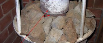
Reducing resistance to the movement of flue gases. For stable combustion in a furnace, it is necessary to round the corners in the path of the flue gases - this reduces the resistance to their movement. For example, on the ceiling of the bread chamber, for this purpose I installed gas distribution shaped bricks to remove gases into the side downward chimneys (photo 17). The width of the outlet holes (two holes on each side) is calculated in such a way that it is convenient to block them. Fireclay core insulation. The fireclay core of the furnace experiences the greatest thermal loads during combustion. As a result, its thermal expansion is greater than the expansion of the remaining parts of the furnace. To prevent this from leading to the appearance of cracks in the furnace, the fireclay core must be separated from the outer masonry by a thermal gap or a layer of basalt cardboard. The fireclay core overlap also needs to be isolated from the underlying masonry. To do this, I laid two layers of basalt cardboard on top (photo 18) and reinforcing mesh over the entire floor area, which I filled with masonry mortar, and on top I laid channels and corners that do not rest on the fireclay core (photo 19).
Iron in the furnace masonry should always be treated with extreme caution, well insulating it from direct contact with brick, otherwise cracks in the masonry cannot be avoided. Therefore, when laying the channels and corners, I carefully packed them in basalt cardboard, and, in addition, separated the channels from the chimney with bricks (fogo 20). It must be said that the channels are used here in connection with the fact. that, according to the masonry conditions, it was necessary to move the pipe to the center of the furnace. If the pipe rested on the outer wall, then the corners would be enough to cover it. Exterior view of the stove. Periodically, at the end of the working day, I washed the stove and removed excess debris. It is more pleasant and safer to work in such conditions [photo 21].
Results
First results. Recently I inquired about how the stove I built behaved and was pleasantly pleased. During the period of operation, not a single crack appeared in the masonry. At the beginning of the fire, the catalyst grate is covered with a thin layer of soot, but then the soot burns out.
The brick oven first warms up in the upper part, but after 2-3 hours it becomes hot throughout the entire massif. In the bread chamber, like in a Russian oven, you can prepare crumbly porridge and baked milk with foam. Even after a day and a half, you can feel the heat emanating from the stove.
The purpose of the old Russian stove
Heating
The main task of a Russian stove is to supply heat to a heated home. Considering the characteristics of harsh Russian winters, maintaining a positive temperature in the house in the old days meant survival. According to this, the stove was considered the main attribute of any living space.
It was placed in the center of the house not only for convenient access. Any room releases heat through openings facing the street. These include doors, windows, as well as cracks in a poorly insulated ceiling or floor. A real Russian stove can warm up a room, regardless of the weather outside.
The washing up
Previously, people very often washed in a Russian oven. Briefly, it happened like this: after the stove was finished heating, the slab was cleaned by removing the ash from there and cleaning out the dust, then covering it with straw. After this, preheated pots were placed there. One with herbal decoction, the other with clean, well-heated water. There was still a place where brooms, washcloths and dried herbs for decoctions were located. Children and old people most often washed themselves in the Russian oven. The nimble guys climbed inside themselves, and the old people were “sent” there on a shovel or a linden board.
Cooking
Food from a Russian oven is significantly different from dishes prepared using modern methods. The secret of aromatic porridges and soups is that they were cooked on cooling coals, which created the effect of continuous simmering of the products. The dishes that were installed at the mouth were usually clay or cast iron. The materials of the cooking containers also contributed to the emergence of an extraordinary taste.
Bed function
Another irreplaceable function of the Russian stove was its use as a bed for sleeping. They slept on the roof, covering it with blankets and zipuns, or on polats - special shelves located between the stove and the wall. It was the stove's job to heat the floor.
Sometimes two-story lofts were built in the hut. Their lower tier was occupied by adults, and children were sent to the upper tier, where it was also always warm.
The wide roofs could accommodate up to six people at once, so on especially cold winter nights the whole family settled down on them, using the couch as a shared bedroom.