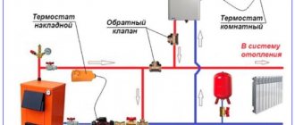
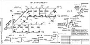
How to reflect structural elements in electronic form
The fastest way to build a drawing is by cloning the entire diagram. To do this, select the “Insert” command, after which the integrated image is flipped. For the function to be executed, it is given a value equal to 45 degrees (the number is written in the program).
Having prepared the basis in the electronic version, where the risers are marked on the plan, they put symbols in the form of dots. To reflect all floors in the building, a vertical line is drawn. For the purpose of better perception, the diagram shows the floor panels.
Important! Don't make the slabs too long. Take advantage of the gap.
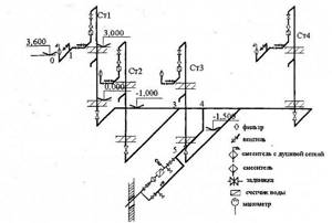
A special feature of the axonometric sewerage diagram is the reflection of all elements of sanitary facilities: urinals, toilets, sinks, drains and other devices for carrying out hygienic procedures.
What does the diagram show?
The axonometric drawing of the sewer must show:
- Pipeline entrances inside the house.
- Wiring of the distribution system in the building (risers and branches from them to each floor).
- Shut-off and control valve elements.
- Adapter rings for pipes with different diameters at their joints.
- Discharge points from the system (tees with plugs).
- Cranes: watering and fire units.
- Sewage equipment, water metering points, control and measuring devices and other components of the sanitary and water supply lines.
Legend
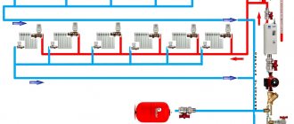
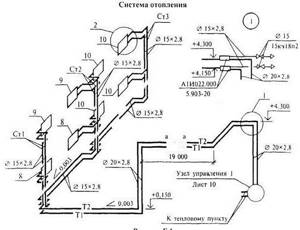
Heating axonometry is compiled according to estimate calculations, determined taking into account climatic features, thermal insulation characteristics of the structure, the type of equipment used and other components included in the heat supply system. Based on this data, installation occurs.
The heating circuit is equipped with the following symbols:
What should be displayed
The axonometry of the water supply and heating system reflects all the maximum information regarding the pipeline. In particular, it displays:
Important! If there are one or more spills on a horizontal bottling area, their size must be indicated.
In addition to the above, the heating axonometry should contain information about the following system components:
In relation to the above-mentioned heating devices, it is necessary to indicate their main characteristics and their type:
Healthy! Regarding other, non-standard heating elements, when drawing up a heating axonometry, their heat transfer coefficient and a detailed description should be indicated.
Required final elements:
Important! All of the above is noted in the schematic representation strictly in the designations assigned to them.
Record order
The above-mentioned standards prescribe the order in which axonometric information about the heating system should be entered. The order of listing the elements is as follows:
Interesting! In fact, in apartment buildings, mortgage pockets remain empty. Thermometers and pressure gauges installed in them are removed after a trial run of the system. The reason for dismantling is related to poorly closing utility room doors and the high cost of measuring equipment.
Scaling Requirements
Depending on the complexity of an individual element, a remote diagram can be drawn up for it. For example, in relation to distribution units, the heating axonometry has a separate drawing, made on a scale of 1 to 50 or 1 to 100.
In this case, a value of 1 in 200 or 1 in 100 is used for the entire axonometric project. In order to obtain detailed images of individual fragments of the heating system, larger values are also used: 1 in 5, or 1 in 10.
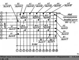
To simplify the subsequent operation and maintenance of heat supply systems, the alignment axes of the structure are indicated. A prerequisite in this case is marks on the distances, the size of the site, and the elevation above the floor level. It is preferable (but not necessary) if the drawing indicates the number of sections of each radiator. For pipelines with piping constructed from finned type pipes (as mentioned earlier), the diameter, quantity and length are prescribed.
Heating axonometry performed for each section separately (for example, for floors, rooms) must have a unique name. For example, the following names may be used:
Healthy! In axonometric drawings of a heating system, longer pipelines are indicated by a broken, dotted line. In addition, a mark must be entered to reflect the actual length of this section.
What data is included in the drawing?
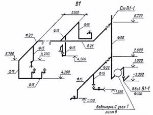
The inclusion of the following indicators describing the water supply system is mandatory when constructing an axonometric diagram. This information includes:
- Designation of risers (usually the leader line area).
- The floor level of each floor of the room, the boundary of the horizontal branch (at the axes of the pipeline), the height of the water collection points (marks along the risers).
- Diameters of system elements.
- Pipeline slope angles (indicating the slope indicator).
- Dimensions (length) of each of the independent sections of the pipeline, which include risers and horizontal branches, in millimeters.
- Coordinating dimensions (secondary information).
- Designation of nodes for the purpose of detailing the drawing.
In addition to a number of basic data, accompanying documentation is attached to the diagrams, including specifications for materials and equipment.
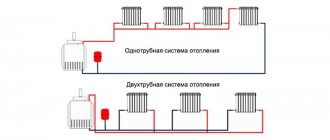
Characteristics of one-pipe and two-pipe systems
The water heating system can be single-pipe or double-pipe. Let's look at the features of each option.
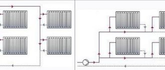
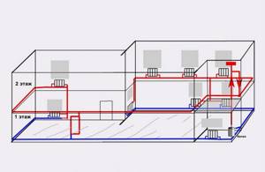
In a single-pipe system, radiators are connected to the supply pipe in series. Its advantages include a simple design and low material consumption, since a minimum of pipes are required to be installed
. But when connected in series to heating devices remote from the boiler, the coolant enters already cooled, and in order to ensure the required level of heating of the air in the room, it is necessary to install radiators of higher power, which increases the cost of the project. Disadvantages also include:
- complexity of hydraulic calculation;
- limitation on the number of heating devices;
- the criticality of errors made at the design and installation stage;
- the inability to regulate the temperature of heating devices individually depending on the requirements for the microclimate of the premises;
- inability to shut off the flow of water to a separate radiator (for repair or replacement, etc.) without stopping the operation of the entire system;
- high heat loss.
The diagram shows the difference between a one-pipe and two-pipe heating system
A 2-pipe heating system, unlike a single-pipe one, provides for a parallel arrangement of supply and return pipelines to which the radiators are connected
. This option has the following advantages:
- allows you to deliver liquid of the same temperature to all radiators (there is no need to increase the number of sections for batteries farthest from the boiler);
- a thermostat can be installed on each heating device;
- additional heating devices can be added to the installed line;
- there are no restrictions on the length of the contour.
Two-pipe heating also has some disadvantages, including the complexity of the connection diagram, increased consumption of materials and labor-intensive installation when compared with the single-pipe option.
It is also worth noting the radial (collector) connection of heating devices - separate supply and return pipes are installed for each radiator. The advantages of independently connecting heating devices include the maintainability of the system - disconnecting any of the circuits will not affect the performance of the remaining radiators. The main disadvantage is the need to lay a large number of pipes.
Typically, water heating of a private house comes down to installing a two-pipe system, since this is the most effective and cost-effective option.
Video: designing water supply and sewerage systems in nanoCAD VK
Sewage systems for summer cottages
The scheme can be oriented in two directions - with connection to central sewer networks and with the organization of a local autonomous network. Therefore, before starting installation, it is necessary to develop a plan that should take into account the following parameters and indicators:
- The dimensions of the house are its height, width and length.
- Places for installing plumbing fixtures.
- Plumbing sizes.
- Methods for connecting devices to.
All this will affect the scheme, which you can do yourself without resorting to the services of specialists.
External sewerage
Plastic pipes are also used to arrange the external part of the sewer system. They are laid in a trench, the depth of which exceeds the depth of soil freezing (for more details: “Installation of external sewerage - options for installation scheme”). The bottom of the trench is covered with a dense layer of sand, after which pipes are laid out on it (here you need to remember the need to maintain a slope). Inspection hatches must be installed at pipe connection points. It would not hurt to install a check valve in the pipeline, which will prevent wastewater from returning to the internal sewer network.
Definition and Application
An axonometric diagram (axonometry) is a graphic representation of a ventilation, heating or air-cooling system in three planes x, y, z. Unlike a two-dimensional drawing, a three-dimensional diagram gives a complete picture of the location of the ventilation system, and this facilitates installation. It forms part of the project documentation.
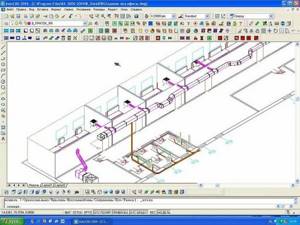
Axonometry of the ventilation system can be made in the form of a manual drawing or using modern computer programs.
The technical capabilities of modern design make it possible to draw up detailed diagrams in volume, rotate them at different angles, and make two-dimensional drawings from axonometry.
Even a powerful computer with a drawing program cannot fully replace a competent designer. Only a professional understands all the intricacies of the ventilation system, and a computer is just a tool.
Concept of axonometry
In simple words, this is a two- or three-dimensional projection that allows you to draw as carefully as possible all the nuances of the heating system. The project is carried out not only in the plane in order to show the slightest slopes and details.
Interesting! A detailed diagram in several projections applies only to the design of heating systems for low-rise buildings. In high-rise buildings (more than 5 floors), only the main distribution node is sketched with all the nuances. Mostly this is an attic or basement floor with outlets that characterize the number of risers.
An axonometric diagram of the heating system is obtained by parallel projection in a given plane of axonometric projections. At the same time, the system of rectangular coordinates OXYZ is used, to which it will be assigned.

Program for creating 3D projections Source cadcamengineering.net
Important! The correct representation of the projection direction is performed so that it does not coincide with the coordinate axes.
Projection options
This is a standardized concept, control of which is entrusted to regulatory documentation approved at the federal level. The drawing projection can be one of the following:
- With a direction perpendicular to the main plane (dimetric, isometric).
- With a direction not perpendicular to the main plane. Here the division is carried out into 3 types: frontal isometric; frontal dimetric; horizontal isometric.
What data is included in the drawing?
The inclusion of the following indicators describing the water supply system is mandatory when constructing an axonometric diagram. This information includes:
- Designation of risers (usually the leader line area).
- The floor level of each floor of the room, the boundary of the horizontal branch (at the axes of the pipeline), the height of the water collection points (marks along the risers).
- Diameters of system elements.
- Pipeline slope angles (indicating the slope indicator).
- Dimensions (length) of each of the independent sections of the pipeline, which include risers and horizontal branches, in millimeters.
- Coordinating dimensions (secondary information).
- Designation of nodes for the purpose of detailing the drawing.

Axonometry of water supply, heating, sewerage
According to GOST 2.317-2011, all axonometric diagrams related to sanitary systems of water supply, sewerage, and heating are constructed in frontal dimetric (oblique) isometry with a left coordinate system.
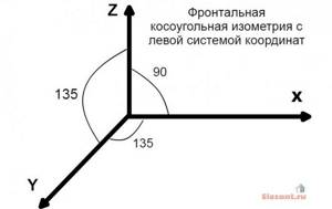
Accordingly, the dimensions along the z and x axes will be without distortion, and the dimensions along the y axis will be two times smaller.
You may ask, what does this drawing have to do with pipes and plumbing installation? Now imagine that the planes along the axonometric axes are the walls of your house or apartment. Plumbing pipes, water supply routes, sewerage and heating pipes run along the walls, vertically or horizontally. This means we can draw pipe routes in axonometry without showing the walls themselves.
This will give very clear drawings of how and where the plumbing wiring needs to be installed. Moreover, plumbing fixtures are marked on the axonometric diagram with symbols, pipe diameters are marked, explanations are made, and tables on materials and equipment are compiled for the diagrams. As a result, you have in your hands a detailed guide on how to install plumbing in a house (apartment), virtually eliminating installation errors.
Features of sketch design
Here attention is focused on the reflection of instruments. If one element climbs onto another, and this happens in most cases, then a dotted line is drawn indicating the displacement of the plumbing element for the purpose of a better visual effect.
The axonometric diagram of the water supply system must include readings of all pipe diameters. If the toilet bowl is not marked on the outlet, then take a diameter of 50 mm; if there is one, the minimum diameter should be 100 mm. These numbers are important to remember. For risers, in 90% of cases, a figure of 100 mm is used. Slopes in a similar diameter will be equal to 0.02; with an indicator of 50 mm, the slope angle is set to 0.03.
If you have already applied all the elements, mark the outlets whose diameter is larger than that of the risers; the slope is taken to be 0.02.
At the last stage of drawing up the axonometry, special notes are made based on the characteristics of the site and the construction plan. Here they note the level of soil freezing, the location of the foundation, as well as other factors that influence the corrections.
Wikonanny rules
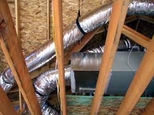
An example of the principle diagram for installing a ventilation system.
Ventilation schemes are usually drawn from the frontal isometric projection (axonometry). This design allows you to create the entire range of wind pipelines in three dimensions, so that, based on the plans or sections, the axonometric coordinate system contains a third of the whole, on which the height values are placed and. Current design programs provide the ability to clearly and quickly draw axonometric diagrams. Although it is not accessible to the skin, the result still needs to be seen on a paper nose. Therefore, such a diagram can be drawn in the hand from a sketch, a design, following a number of rules for drawing axonometric diagrams. By following them, you see a complete picture of the tide or exhaust system on the paper.
Start by selecting the right location for the location or where the ducts will be laid.
In accordance with the rules, it is necessary to choose the angle from which the façade will be, which is laid out on the plan below, the outer wall of which façade is designated by the first letter of the whole. If you are drawing a simple sketch of one location, then you can draw it out as carefully as possible, but remember that during the official preparation of documentation the chair will have to be reworked. The system's conductors should be applied according to the following principle:
- If the channel runs parallel to the façade specified for the design, it should be applied as a horizontal line;
- the wind duct perpendicular to this façade is drawn on the diagram at 45 degrees to the horizontal according to the same scale;
- vertical plots are marked with vertical lines.
Scheme of internal sewerage of a private house
The construction of an internal sewerage network in a private house is determined by the size of the premises, as well as the relative position of all plumbing fixtures. All objects into which waste water is discharged in the house must be connected to the sewer system. These could be sinks, toilets, bathtubs, and so on.
Scheme of internal sewerage of a private house
All elements of the system are connected to a common sewer riser via polypropylene pipes. Sewage riser diagram
quite simple. It must be positioned strictly vertically. In this case, the use of several risers is allowed. This should only be done if the room is large enough and the distance between plumbing fixtures is large.
The entire pipeline is connected using fittings. However, you can go the other way, that is, use a socket connection. Some use other common methods for connecting polypropylene pipes. They weld and glue well.
Sewerage assembly
Sewerage assembly
If a hidden sewer system is used in a private house, then inspection windows will have to be provided. This is done so that the condition of the pipes can be monitored without much difficulty. Those pipes that are located at the bottom of the foundation must be connected to the external pipeline. To do this, you need to punch a hole in the foundation, the diameter of which will be slightly larger than the diameter of the pipe.
So, the main parts of the internal sewage system of a private house are:
- a deflector installed at the end of the ventilation pipe;
- a common sewer riser, which serves to drain wastewater from all plumbing fixtures located in the house;
- sewer lines installed at a certain slope;
- socket or fitting connections (can be combined);
- directly sewer pipes that are connected to all plumbing fixtures and devices located in the house.
Axonometric diagram of the sewer system
An axonometric diagram of a sewer system serves to visually depict all its components. It fully describes all the components that are included in the design. Today, drawing up an axonometric diagram is becoming very important. It is done in accordance with all regulations and documents. All elements are depicted schematically on it. Of course, not everyone will be able to understand this kind of application, but for an experienced plumbing worker this presents absolutely no difficulties. In accordance with it, the subsequent installation of the entire sewerage system is carried out.
What is better - natural or forced air movement?
The choice of air exchange device concept is determined by the specific operating conditions of the room. The merits of each system should be taken into account. In particular, the advantages of natural ventilation include:
- Inexpensive infrastructure available to build for private homeowners.
- The absence of mechanics eliminates the need for regular maintenance and installation of power supply lines.
- There are no maintenance costs. It is enough to periodically clean the channels, which requires minimal investment and effort.
- No noise due to a running fan.
The result is a simple system that is easy to use, but at the same time it gives a modest effect in terms of ventilation.
Now you can consider the advantages of a forced air circulation system:
- Regardless of external conditions, it can provide sufficient ventilation.
- In addition to circulation as such, it allows you to perform the functions of cooling, heating and filtering air masses.
- The possibility of organizing a heat exchange system involves practically free heating of the incoming masses.
The disadvantages of forced air exchange are due to the difficulties in installing and maintaining ventilation equipment, which will also require additional space for installation.
Determination of axonometric heating diagram
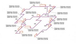
Axonometry is one of the sections of applied drawing that studies, examines and provides the opportunity to obtain fairly accurate images of any objects in two or three projections. A rectangular axonometric projection is when the straight lines that project the image of an object are located perpendicular to the axonometric plane of projection. Rectangular projection includes isometric and dimetric. If the projection angle is not equal to 90°, then such a projection is called oblique axonometric. It also includes frontal dimetric and trimetric projections.
Manifold wiring in oblique axonometric projection
It follows that an axonometric heating diagram is any diagram of any heating of a multi- or low-story building, made in axonometry, and not in one plane. This helps to more clearly imagine the wiring and other elements of the heating system in real terms. With this approach to displaying heating elements, the projection of each object is performed as follows:
- The element is located on the diagram according to all three coordinate axes;
- The “picture plane” is defined – the element will be projected onto it. In this case, the “picture plane” should not run parallel to any of the coordinate axes;
- The projected node or element is completely transferred to the diagram.
Important: Since all coordinate axes do not run parallel to the picture plane, the object's projection image will have a difference in real and displayed sizes at any scale.
Correctly drawn up axonometric drawing of a heating circuit
Requirements for drawing up drawings of heating and other systems of a residential or industrial building are defined in GOST 21.602-2003. All heating elements and components according to GOST have their own designations: this is the marking and serial number included in the drawing. The following notations are used:
| Element or node | Marking |
| Heating riser | St |
| Main heating riser | Gst |
| Compensator | TO |
| Horizontal piping | GW |
| Thermometer | T |
| Pressure gauge | R |
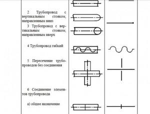
Fragment of GOST 21.206-93 for designations of pipes and pipeline connections
According to GOST 21.206-93, pipeline systems are indicated graphically. This applies to the following nodes:
- Common pipeline;
- Vertical riser directed downwards;
- Vertical riser directed upward;
- Flexible pipeline;
- Pipe crossing without connection;
- Simple connection of the pipeline or its elements;
- The connection of the pipeline or its elements is flanged;
- Coupling threaded connection;
- The coupling connection is quick-release;
- Socket connection.
The designations of shut-off valves, radiators and other elements are displayed in GOST 21.205-93. For example, such as:
- Wash basin;
- Foot bath;
- Toilet;
- Heating thermostat;
- Shower net;
- Air Dryer.
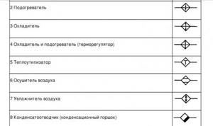
Fragment of GOST 21.205-93 for designations of shut-off valves
Any axonometry cannot be displayed using standard means allowed in GOST, and for this there are additional requirements and permits. For example:
- Elevation and level marks can be moved outside the element or indicated directly on the contours of objects;
- An axonometric drawing of a heating circuit with bottom wiring or any other circuit can be made on a scale of 1:50, 1:100 or 1:200.
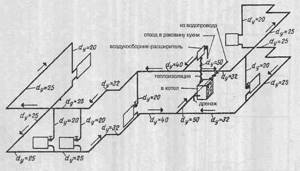
What should be visible as a result?
Figure 2, 3. Schemes of ventilation systems.
Figure 2 shows as an example an axonometric diagram of supply ventilation with mechanical stimulation. It shows at what marks the air ducts are laid and what diameters the dampers are installed to regulate the flow on each of the 4 branches. In front of them there are hatches for measuring air speed, and each branch ends with an air distribution device.
That is, this diagram contains all the necessary data for calculating or installing the system; ideally, each diagram should be drawn this way.
The second example in Figure 3 shows an exhaust ventilation system with local exhaust in the form of umbrellas and equipment for cleaning contaminated air (cyclone). From the drawings shown as examples, it is clear that the designations of the air ducts, if necessary and of high complexity, can be broken in order to move part of the diagram to the side. Then the places of breaks are marked in lowercase letters, and a thin dotted line is drawn between them. The axonometry is drawn in accordance with the scale; according to the standards, they can be taken as 1:50, 1:100; 1:200.
List of equipment and parameters on the diagram
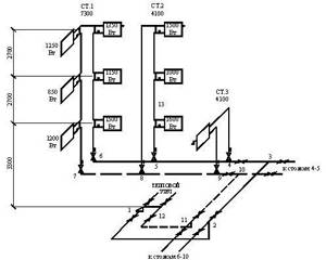
The heating diagram of any floor should indicate:
- Pipe distribution indicating all pipe diameters;
- Pipe insulation areas - length and thickness. Such thermal insulation is indicated graphically;
- Piping axes relative to zero level;
- Slope angles of bottlings;
- If there are gaps in the horizontal sections of the bottlings, then the dimensions of these sections are indicated;
- Supporting and hanging elements, compensators.
Important: if an element or section of the diagram should be displayed graphically, then an extension shelf is drawn above this image, and the type of assembly or part is indicated above it. The number of the document corresponding to this element is indicated under the heading.
An example of markings on a heating diagram
- The remote shelf is used to identify shut-off valves, indicating their marking and type. Under the offset, the part designation is indicated according to the documentation (see figure above);
- Vertical horizontal piping with appropriate designations;
- All heating devices present in the circuit.
Mandatory requirement: it is necessary to indicate the type and main characteristics of these elements:
- How many sections does the heating radiator contain?
- How many sections or pipes are in the heating register, its diameter and total length;
- For other heating devices (convectors, radiators) – type of device;
- Designations of thermal installations (boilers, heating furnaces and heat exchangers, circulation and heat pumps, elevators, etc.);
- Mortgage equipment;
- Measuring instruments.
Heating diagram to scale
Interesting: According to GOST requirements for multi-apartment (for example, 5 or more floors) buildings, a detailed diagram of heating equipment can be drawn up only for the basement. A piping diagram for the basement and, if necessary, an attic wiring diagram are drawn separately. The impossibility of drawing up a detailed diagram is due to the difficulty of visualizing all utilities in an axonometric projection in a multi-story building.
Heating equipment and calculations
All equipment used in the heating system is divided into auxiliary and main. The main one is a boiler or other heating device, the auxiliary one is radiators and distribution pipes with the accompanying fittings. To calculate the parameters of the required heating equipment, the specific power of the boiler is required, which varies depending on climatic zones:
- For regions of the Far North - 1.5-2.0 kW;
- For temperate climate zones and central regions - 1.2-1.5 kW;
- For southern zones - 0.7-0.9 kW.
Based on these amendments, the power of the heating device is calculated using the formula:
W boiler = S x W / 10;
Where W is the design power of the heating device (boiler, convector, etc.);
S – total area of the heated object.
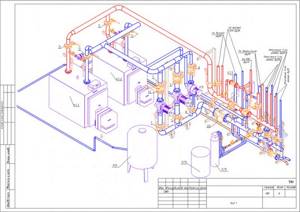
Axonometric diagram of boiler equipment with two burners
Pumps are either heat or circulation pumps. In most cases, except for low-rise buildings with natural coolant circulation, it is impossible to do without pumping equipment, so these devices are present in almost all diagrams. Pumps must meet certain technical requirements, including the following:
- Ease of installation, dismantling, ease of operation and maintenance;
- Low noise and economical device;
- Reliability and durability.
In low-rise residential buildings, three types of heating systems are used:
- The classic two-pipe scheme, according to which hot water is supplied through one pipe and returned through the second. In this scheme, the pump is mounted on the return line;
- Scheme with a vertical riser. In this scheme, hot water is also supplied to the radiators through one pipe and returned through the second, but a circulation pump is installed on the outlet pipe to supply hot coolant. Thus, hot water first passes through the upper radiators and then moves to the lower radiators of the system;
- The single-pipe scheme involves the movement of coolant sequentially from radiator to radiator with return to the boiler. This is the simplest scheme, but due to its low efficiency it is used in small one-story buildings.
Simplified axonometric two-pipe diagram
Calculations when drawing up a heating scheme should take into account:
- Heat consumption in each room;
- Type and number of radiators;
- The number of risers, if any, as well as the total number of branches and circuits;
- Connection diagram for heating devices;
- Parameters of pipes and shut-off valves.
After completing the calculations of the heating system, they must be indicated on the diagram. The main purpose of an axonometric heating diagram is a graphical display of all parts and elements, but, in addition, the diagram must also display the technical characteristics of the heating equipment. The diagram must also include calculations for the heat supply to each room of the house, including utility rooms.
How to make axonometry
As it became obvious, the information contained in the executive documentation is written in accordance with the established algorithm of abbreviations and markings. The easiest way to create an isometric image using architectural programs is to use AutoCAD. Working with it begins with selecting a suitable plane, after which, using the built-in auxiliary tools, the specified parameters are selected and the desired construction is carried out.
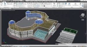
Program for creating 3D drawings AutoCAD Source user-life.com
Important! As already mentioned, the main advantage of working with special programs is the presence of all standards and rules in the basic settings (the system prompts the necessary parameters independently). With the help of such virtual assistants, axonometry of ventilation or heating does not seem such a difficult task.
Axonometry of a ventilation duct constructed using AutoCAD Source www.club-gas.ru
AutoCAD is a two- or three-dimensional program designed for automated architectural design. First released in 1982. Today it is used in almost all industries and construction. Including private, low-rise ones. Its localization level is designed so that it can work in 18 languages. Not only the help documentation is translated into Russian, but also the entire interface, including the command line. The exception to the Russified version is the programming manual.
Manual assembly
If the axonometry of ventilation, heating, and air conditioning is constructed manually, without using programs, it is necessary to take into account the requirements of the previously mentioned state standards. This option is one of the most complex and involves the creation of 2 types: a sketch and a full-fledged drawing.
The sketch is not an official option. Therefore, it is not subject to strict requirements. And the drawing comes with certain obligations. This primarily concerns the following:
- Choosing the right viewing angle. This point is the primary task that the designer must solve. A detailed analysis of the floor plan (for buildings with several floors) will facilitate the task. The drawing should be positioned in such a way that the bottom is adjacent to the designer, the left hand is slightly below the first axis of the structure, and the right hand is under the last axis. The closest point of the facade should be the left corner of the building. This will be used as the starting point for the axonometric drawing.
- Pipe line orientation detection. The solution to this problem is much simpler. The network, which runs parallel to the near and far walls of the building, is depicted as a horizontal line parallel to the walls.
- Correct scaling.
Healthy! If the drawing dimensions do not fit on the sheet, tears may occur. In this situation, a dotted line is placed on the drawings (on both sheets).
Axonometric drawings of heating and ventilation branches
When working with utility networks, calculations and graphical visualization act as important components of work on a residential construction project. In addition to the plan of the house and its facade, the package of documents required for construction is supplemented by an axonometric diagram of communications. Using it you can visually study this or that network: water supply, heating, ventilation. The use of such drawings is especially important when arranging complex systems. Having an axonometric view of the heating project simplifies the work of installers during the process.
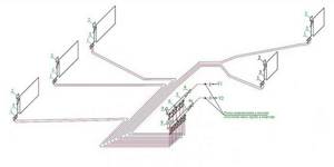
Axonometry in PT rules of execution
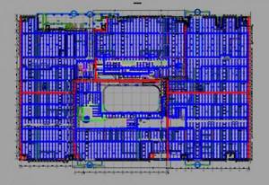
For example, let’s take the project of a fire sprinkler system for a shopping and entertainment complex.
Key points of such a project:
- piping;
- distance between sprinklers;
- type of pipeline fastening;
- automation kit for the PT system.
We are mainly interested in the layout of the pipeline network.
The elements of the drawing for the pumping station, network drainage flanges, etc. are also taken into account here.
An axonometric diagram of such an AUPT may look like this.
GOST 2.317-69 establishes the procedure and rules for performing axonometric projections for engineering systems.
When performing axonometry in fire fighting, we cannot do without the well-known SP 5.13130.2009.
We calculate the distance between sprinklers according to NPB 88-2001.
Pipeline design standard - GOST 10704-91.
We are guided by these standards when creating a three-dimensional projection of the pipeline network.
For all complex construction drawings, floor plans of high-rise buildings,
buildings with a complex ventilation system - wherever there is complex pipework,
An axonometric projection must be included in the design documentation.
So, in accordance with GOST 2.317-2011, such a projection is constructed in frontal isometry, i.e. in three planes, in the left coordinate system.
Paragraph 3.2.1 of the GOST 21.602-79 document also states that it is necessary to take into account the distortion coefficient along the axes, taken conventionally as unity.
These are any drawings of heating, sewerage, plumbing systems, etc.
The axonometric diagram includes two types: a full-fledged drawing and a sketch.
We carry out a full-fledged drawing in accordance with all GOST requirements.

What needs to be seen as a result?
Figure 2, 3. ventilation schemes.
Figure 2 gives an example of a perspective diagram of ventilation with mechanical drive. It shows on what marks laid ducts and any diameter installed valve to adjust the flow in each of the four branches. In front of them hatches are arranged for measuring air velocity, and each branch ends with air diffusers.
That is, in the scheme contains all the necessary data to calculate a mounting system, so ideally should be drawn each scheme.
The second example in Figure 3 shows the exhaust ventilation system with local suction in the form of umbrellas and for cleaning polluted air equipment (cyclone). From the examples shown in the drawings it is seen that ducts designations when necessary and high complexity can break to move the part towards the circuit. Then place mark breaks in lowercase letters, and carried a thin dotted line between them. Axonometry drawn to scale, according to rules they can take the 1:50, 1: 100 to 1: 200.
Ventilation systems can be either simple, in which there are 2-3 elements, or foldable, if a number of surfaces penetrate the air ducts and distribute them to non-personal areas.
In order to avoid problems during the installation of ventilation, it is necessary to create a design or installation of the entire system as a whole.
In order to properly design and subsequently install such a ventilation system, it is necessary to display it on paper or on a computer, ideally - simultaneously with plans and actual layouts. Since the diagram is awkward and is located within one space, the cuts can not be drawn out.
Axonometric drawings of heating and ventilation branches
When working with utility networks, calculations and graphical visualization act as important components of work on a residential construction project. In addition to the plan of the house and its facade, the package of documents required for construction is supplemented by an axonometric diagram of communications. Using it you can visually study this or that network: water supply, heating, ventilation. The use of such drawings is especially important when arranging complex systems. Having an axonometric view of the heating project simplifies the work of installers during the process.
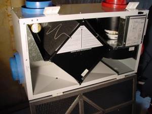
Technical organization of the air exchange system
There are different concepts and principles for arranging ventilation and airing systems. In the most optimized version, this will be a set of grilles with direct air exhaust channels that ensure the supply of street air. Standard home air circulation systems involve the organization of horizontal and vertical shafts. This infrastructure is carried out using metal or plastic air ducts of different sections. These can be rectangular and round, flexible and rigid structures, which are usually installed according to the principles of hidden installation.
What to pay attention to when creating a sketch
Before reflecting the axonometric diagram of heating a room in paper or electronic form, a number of calculations are carried out. The diagram itself is compiled based on the collected data:
- heat demand values for building rooms;
- typologies of heating devices, their quantities for each room;
- basic decisions regarding the entire engineering network: the use of risers, calculation of hydraulic branches and circuits, the order of connecting elements of the heating system;
- characteristics of pipeline sections: diameters and lengths of pipe fragments, shut-off valves, thermal controllers, hydraulic regulators.
Having received the appropriate calculations, their indicators are entered into the diagram. The axonometric diagram of the heating system necessarily contains the technical characteristics of each of the network nodes (boilers and pumps used), the length and diameter of the pipes, heat consumption and information about other thermal properties of heating devices, such as radiators, convectors, registers.
When starting to work on an axonometric drawing, first of all, the main ring of coolant movement is determined - the path to the most distant element from the boiler and back.
To summarize what has been studied, we will say that axonometry is mandatory, regardless of the type of communication system for structures of any type of purpose. Having a graphical drawing in front of their eyes, installers quickly determine how much work needs to be done and what exactly the network looks like.
If a specialist understands the axonometric heating diagram, and the drawing itself is executed correctly without any errors, then during the implementation of the project it is possible to eliminate the occurrence of any difficulties associated with the installation of elements of the heating system, pipelines and other utility networks.
In order for the design, and then the installation of the water supply system, to be successful, it is necessary to correctly visualize the building itself and the communication branches inside it on a sheet or in electronic form. In this case, the graphical component of the project includes:
- general plan of the building;
- situational diagram;
- facade;
- plans for each floor;
- roof plan;
- axonometric diagrams: ventilation, heating, water supply;
- sections and other schematic diagrams.
Remember that when working with correctly designed axonometry, problems with the installation of utility networks do not arise in 99.9% of cases. That is why this stage is so important in designing a future house or high-rise building.
Basic Rules
As mentioned earlier, the main criteria regarding the preparation of an axonometric projection of heating, ventilation or air conditioning systems are prescribed in state standard 21.602-2003.
General provisions according to state standards
According to GOST 21.602-2003, heating axonometry is developed in accordance with conditions that refer us to GOST 21.101 and a number of additional state standards. Following the link, the working documentation includes the following papers:
- Working drawings used when carrying out construction and installation work (OV drawings).
- Sketches depicting general types of non-standard products.
- Documents confirming the specifics and quality of the equipment and components used.
Important! The presence of questionnaires, local estimates and dimensional drawings may be required only by agreement with the customer.
The list of main OB drawings includes:
- General information on working schemes.
- Projects, sections, diagrams of mounted systems and their installations.
Important! It is allowed to include installation diagrams of heating units among the main drawings of heating units, provided that their input diameter does not exceed 150 mm.
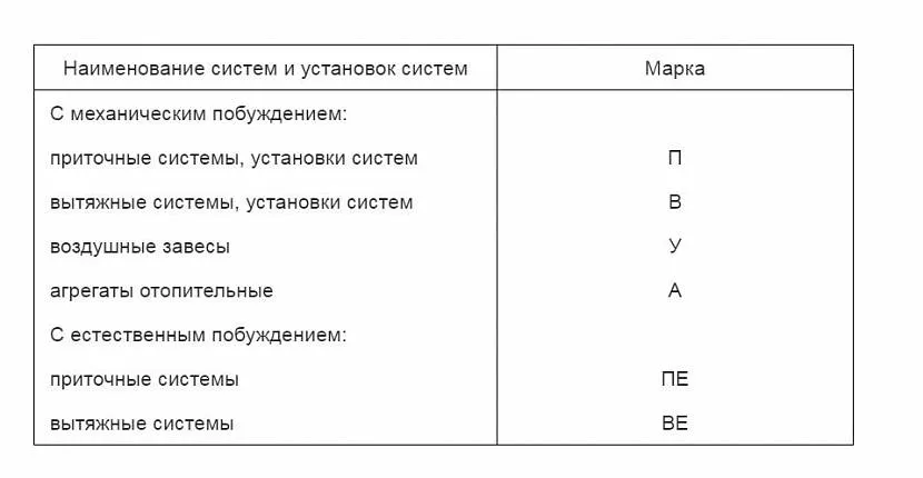
Conditions for marking heating systems in accordance with GOST 21.602-2003 Source docs.cntd.ru
Each system receives a name, which is built from the corresponding mark (indicated in the table shown in the image). The second value is the serial number of the system within the boundaries of the above-mentioned brand.
Heating system installations receive names similar to the systems they are part of.
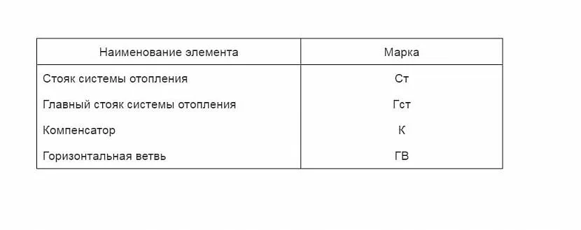
Marking of components of heating systems according to GOST 21.602-2003 Source docs.cntd.ru
The individual components of the heating system receive a designation based on the brand shown in the table in the image and the ordinal value of each fragment within its limits.
It is possible to index individual risers using capital letters. This condition applies only to risers.
The pipeline line in the axonometry of ventilation or heating systems, as well as their components, are displayed with graphical schematic symbols, the list of which was mentioned earlier. This marking is approved in accordance with GOST 21.206, which contains all the necessary tables characterizing the conditions of their use.