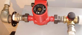
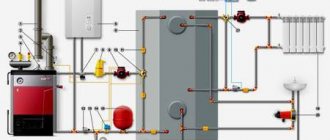
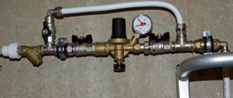
Such a pump is used as part of a heating system to ensure forced circulation of the coolant. The device runs on electricity and consumes little energy - from 60 to 100 watts, which is comparable to a regular household light bulb.
Unfortunately, if the power supply to a private home is interrupted from time to time, then the operation of the pump will be inconsistent, which will lead to disruption of the movement of fluid through the pipes. Before installing the pump, it is recommended to think in advance about how to make the water circulation in the circuit constant.
Connecting an electric boiler to the heating system
piping of an electric heating boiler Electric heating convectors: how to choose - little tricks
To reduce the amount of electricity consumed, it is advisable to resort to the following scheme:
- install a heated floor system that distributes heat evenly throughout the room;
- install a heat accumulator - a heat-insulated storage tank. In it, the water will be heated at night, when a lower electricity tariff is in effect, and during the day it will slowly cool, releasing heat into the room (more details: “Correct heating scheme with a heat accumulator”).
Connecting an electric boiler to the heating system: instructions
Advantages of the pumping system and its disadvantages
The presence of a pump in the heating circuit gives the system several significant advantages:
- Easy to install
. This advantage is significant compared to the natural system. The fact is that when installing a circulation pump, there is no need for complex installation of the upper pipeline, there is no need to weld pipes maintaining an angle of 300 and install main risers of large diameters. - Uniform and rapid heating of the home
. Unlike natural circulation, in which heating of radiators depends on the distance to the boiler, when using the pump version, the coolant enters all batteries at the same time, and if any dissonance occurs, it can be adjusted. - Heating a large area
. This can be done if you choose a collector-type pipe layout. This ensures uniform heating of the radiators, no matter what distance they are from the boiler. Therefore, it is possible to extend the pipeline system to the required length without fear of losing heat during transportation due to its large length. - Possibility of using antifreeze
. It will provide the system with frost protection. - Heating adjustment
. It is carried out over separate sections of the network. Using the provided control valves, entire sections of the pipeline can be closed. Due to this, you can change the network layout and redo its connection diagram. - Extending the service life of equipment
. Boiler devices in a closed system practically do not suffer from temperature differences; it is less noticeable at the inlet and outlet of the boiler. - Possibility of introducing additional elements into the system.
The presence of a circulating pump makes it possible to install “warm floors”. - There is no need to adjust the water in the system.
By including a pump and an expansion tank with a membrane in the heating circuit, and making it closed, we were able to reduce the evaporation of liquid from the system.
Types of circulation pumps
A pump with a “wet” rotor is made of stainless steel, cast iron, bronze or aluminum. Inside there is a ceramic or steel motor
To understand how this device works, you need to know the differences between the two types of circulation pumping equipment. Although the fundamental design of a heating system based on a heat pump does not change, the two types of such units differ in their operating features:
- A pump with a “wet” rotor is made of stainless steel, cast iron, bronze or aluminum. Inside there is a ceramic or steel motor. The technopolymer impeller is mounted on the rotor shaft. When the impeller blades rotate, the water in the system is set in motion. This water simultaneously functions as an engine cooler and a lubricant for the working elements of the device. Since the “wet” device circuit does not provide for the use of a fan, the operation of the unit is almost silent. Such equipment only works in a horizontal position, otherwise the device will simply overheat and fail. The main advantages of a wet pump are that it does not require maintenance and also has excellent maintainability. However, the efficiency of the device is only 45%, which is a minor drawback. But for domestic use this unit is perfect.
- A pump with a “dry” rotor differs from its counterpart in that its motor does not come into contact with the liquid. As a result, the unit has less durability. If the device operates “dry,” then the risk of overheating and failure is low, but there is a risk of leakage due to abrasion of the seal. Since the efficiency of a dry circulation pump is 70%, it is advisable to use it to solve utility and industrial problems. To cool the engine, the device circuit provides for the use of a fan, which causes an increase in the noise level during operation, which is a disadvantage of this type of pump. Since in this unit water does not serve as a lubricant for working elements, during operation of the unit it is necessary to periodically carry out technical inspection and lubricate parts.
In turn, “dry” circulation units are divided into several types according to the type of installation and connection to the engine:
- Console. In these devices, the engine and housing have their own place. They are separated and firmly fixed on it. The drive and working shafts of such a pump are connected by a coupling. To install this type of device, you will need to build a foundation, and maintaining this unit is quite expensive.
- Monoblock pumps can be used for three years. The body and engine are located separately, but are combined by a monoblock. The wheel in such a device is installed on the rotor shaft.
- Vertical. The service life of these devices reaches up to five years. These are sealed advanced units with a seal on the end side made of two polished rings. For the manufacture of seals, graphite, ceramics, stainless steel, and aluminum are used. When the device is running, these rings rotate relative to each other.
There are also more powerful devices on sale that have two rotors. This dual circuit allows you to increase the performance of the device at maximum load. If one of the rotors fails, the second can take over its functions. This allows not only to enhance the operation of the unit, but also to save energy, because with a decrease in heat requirements, only one rotor works.
Pump operating principle
Circulators operate on electricity. There are two approaches to the system, which leads to their division into “dry” and “wet” type devices.
The principle of operation of a dry chain is that the drive is completely isolated from each pump and turbine, and rotation is transmitted through the shaft. As a rule, such devices are quite massive.
Dry pumps for circulating water in a heating system are powerful and efficient devices that provide very high flow rates and high pressure in the system.
Without them it is difficult to control the heating. They must be installed in an apartment or private house. However, there are some disadvantages:
- The shaft that transmits rotation is a complex sealing system that prevents leakage of liquid under pressure. These seals gradually wear out, requiring regular preventive maintenance, including replacement with new ones.
- The operation of the pump is always accompanied by an air-cooled sound effect.
Finally, the system is a very expensive choice; the best option would be to purchase a wet rotor pump. The vertical wet rotor pump also comes in different types.
Source: https://pochini.guru/byt/ustanovka-tsirkulyatsionnogo-nasosa
Water heating systems
Water heating is a method of heating rooms using a liquid coolant (water or water-based antifreeze). Heat is transferred to the premises using heating devices (radiators, convectors, pipe registers, etc.).
Unlike steam heating, water is in a liquid state, which means it has a lower temperature. This makes water heating safer. Radiators for water heating have larger dimensions than for steam heating. In addition, when heat is transferred over a long distance using water, the temperature drops significantly. Therefore, they often make a combined heating system: from the boiler room, with the help of steam, heat enters the building, where it heats the water in a heat exchanger, which is already supplied to the radiators.
In water heating systems, water circulation can be either natural or artificial. Systems with natural circulation of water are simple and relatively reliable, but have low efficiency (this depends on the correct design of the system).
A disadvantage of water heating is also air pockets, which can form after draining the water during heating repairs and after severe cold snaps, when the temperature in the boiler rooms is increased and part of the air dissolved in it is released from it. To combat them, special release valves are installed. Before the start of the heating season, air is released using these valves due to excess water pressure.
Heating systems are distinguished according to many characteristics, for example: - according to the method of wiring - with upper, lower, combined, horizontal, vertical wiring; - according to the design of the risers - single-pipe and double-pipe;
— along the flow of the coolant in the main pipelines — dead-end and associated; - according to hydraulic modes - with constant and variable hydraulic modes; - according to the communication with the atmosphere - open and closed.
Open system configuration
Structurally, the main line consists of main and auxiliary components - a boiler, a circulation pump, an expansion tank, pipelines, and batteries. It is worth considering all the elements in more detail.
Boiler
In order for open-type heating to work smoothly, you need to select the correct boiler power.
A lack of indicator will result in poor coolant circulation, an excess will result in increased costs, as well as:
- formation of condensation in the chimney;
- reduction in the service life of system elements;
- inefficiency of the boiler, which is not designed to operate at reduced loads;
- automation failure.
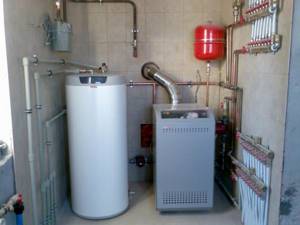
The power calculation is made using a complex formula, but you can get by with the standard - for 10 m2 of area, 1 kW of power is required, plus 15-30% of the reserve. Thus, the calculation is performed quite quickly. Equipment manufacturers also provide assistance by posting free calculation calculators on their websites, taking into account all the features of the house - insulation, wiring diagram, number of radiators, etc.
Circulation pump
Despite the fact that the gravity design is in demand, an open heating system with a circulation pump is more efficient, so this unit should be provided for buildings with an area of 50 m2 or more. Installing the device reduces operating costs, and electricity consumption is no more than that of a conventional incandescent lamp.
The pump is selected not only by diameter, but also by performance and the power of the liquid pressure created. All parameters are indicated in the technical data sheet and additional recommendations from the manufacturer, so it is imperative to read the instructions.
Expansion tank
It will not be difficult for a craftsman with minimal welding skills to make a tank with his own hands. It is important to take into account the total volume of the coolant and make a tank with a reserve of space for water expansion (approximately +10% of the total volume). When making a tank, preference should be given to metal that is resistant to corrosion processes.
Heating radiators
Batteries are a mandatory design element that transfers coolant energy to the air in the room.
Radiators differ according to the material they are made of:
- Cast iron radiators. Durable, corrosion-resistant, expensive devices with a long service life. The large mass and high inertia of the units are a plus for an open heating system.
- Steel appliances are lightweight but susceptible to corrosion. You should choose devices with anti-corrosion coating, which have reduced thermal conductivity. Otherwise, heating costs will increase significantly.
- Aluminum batteries are considered the best choice. Lightweight and durable devices have good heat transfer and heat capacity. Installation is simple.
- Bimetallic batteries are a leader in the combination of qualities and optimal cost. There are no disadvantages, but it is better to use such devices in systems with constant high pressure. When choosing a gravity circuit, installing bimetallic radiators is impractical.
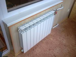
Preparing water for the heating system and how to soften it correctly
Important! Before choosing the type of devices, it is necessary to calculate the number of batteries that will be built into the highway. It is likely that 3-4 units are enough to fully heat a house; in this case, cast iron batteries are more than justified.
Pipes of an open heating system
The selection of highway elements is made taking into account the diameter, wiring diagram and material of manufacture of the parts, in particular:
- metal pipes are difficult to install, are expensive and are not used in autonomous heating systems;
- copper ones have an extremely long service life, can withstand any load, but are expensive;
- metal-plastic is the best option, but you will have to regularly check the strength of the connections and tighten the joints to reduce the risk of leaks;
- pipes made of cross-linked polyethylene are well suited for forming a thermal system, and simple assembly into fittings facilitates installation, however, the choice is complicated by a large number of “handicraft” products that do not meet safety and practicality requirements;
- polypropylene elements are considered the best; such a line is easy to install, lasts a long time and does not require special care.
Important! To get high-quality open-type water heating with a pump, you should choose reinforced polypropylene pipes. The machine for soldering joints is expensive, but can be rented. Fiberglass pipe reinforcement is better than aluminum.
Power determination
When choosing a pump, you need to consider factors such as:
- power of heating radiators;
- coolant movement speed;
- total pipeline length;
- flow section of pipelines;
- boiler power.
Calculations
To more accurately determine the pump power, you can use the rule of 1 kW of power per 1 liter of pumped water. Thus, a 25 kW pump can circulate a maximum of 25 liters of coolant.
Sometimes a simplified selection scheme is used, based on the area of the heated room:
- to heat buildings with an area of up to 250 m2, buy a pump with a capacity of 3.5 cubic meters of water per hour and a pressure force of 0.4 atmospheres;
- from 250 to 350 m2 - with a capacity of 4.5 cubic meters per hour and a pressure force of 0.6 atmospheres;
- from 350 m2 - with a capacity of 11 cubic meters per hour and a pressure force of 0.8 atmospheres.
European calculation method
When choosing equipment, you can use another method - standard housing improvement projects developed in the European Union. So, per 1 m2 of space there should be a pump power of 97 Watt, provided that the air temperature outside is 25C° (minus), or 101 Watt if the temperature drops to 30C° (minus).
This norm applies to buildings with a height of three floors or more. When arranging a private house up to two floors high, the pump power per 1 m2 of area should be 173 Watts at street temperatures up to 25C° below zero and 177 Watts – below 25C°.
Varieties of scheme
The very name of the scheme implies the use of a circulation pump, the purpose of which is to provide pressure and constant movement of heated water.
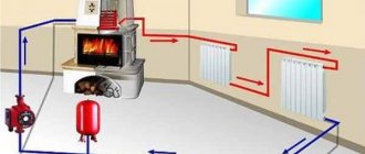
Briefly, the operating principle of the circuit looks like this: water heated to the required temperature is supplied through a pipeline to the radiators. After cooling, it returns to the boiler through the outlet pipeline. The built-in expansion tank provides constant coolant pressure and is designed to withstand the volume of water increasing during heating. There are several varieties of such a system, divided according to the following characteristics:
- according to the method of connecting the pipeline to the radiators: single-pipe and double-pipe;
- according to the location of the risers: vertical risers and horizontal risers;
- by type of main: dead-end systems and systems with associated water movement;
- by type of wiring: from the top and from the bottom.
Let's figure out how to connect a circulation pump for heating according to each of the indicated schemes.
One-pipe and two-pipe systems
Considered a relic of the past, the single-pipe design involves connecting only one pipe to the radiator.
All heating devices in the house are connected in series, and the coolant flows through them, starting from the top and ending with the bottom, giving off more and more heat with every centimeter of progress. Thus, the water reaching the last of the radiators is barely warm, and this creates a strong imbalance in the temperature of different rooms. The only way to somehow reduce this difference is to install radiators with a large number of sections in the lower rooms. Other disadvantages include:
- the inability to install control valves, since this will automatically shut off or reduce the access of water to the radiators “downstream”;
- unregulated temperature in heated rooms: if the heating system is running, all rooms will be heated.
The single-pipe system was popular half a century ago, but nowadays it is completely outdated and is practically not used.
The two-pipe design eliminates these disadvantages by connecting an inlet and outlet pipe to each battery. In this case, the coolant that loses its temperature is removed from the radiator to the boiler for new heating, and does not move to the next radiator. Another additional advantage: the ability to install on each radiator its own control valve or automatic thermostat.
Vertical and horizontal risers
Connecting radiators to a vertical riser allows pipes to be supplied to them not immediately, but separately for each floor of the high-rise.
The main advantage of vertical risers is the absence of air locks. The disadvantage is the relatively high cost. For slightly different purposes, the installation of a circulation pump in a heating system with a horizontal riser is used: heating staircases, corridors and any large one-story buildings. Its significant advantages are savings on pipes and the resulting low installation costs. A known drawback: the appearance of air jams, which, however, Mayevsky cranes help eliminate.
Dead-end and passing schemes
A widespread dead-end system involves the movement of coolant through the supply pipe in one direction, and through the outlet pipe in the opposite direction. The circulation rings differ significantly in length. Disadvantage of a dead-end system: uneven heating. Those heating devices that are closer to the boiler are more efficient than those that are further away. Even connecting a circulation pump to a dead-end heating system does not guarantee that all radiators will heat equally well. The advantage of such a system: efficiency. Their shortcomings are often smoothed out by installing several small lines instead of one long one. In a passing circuit, the length of the circulation rings is always the same. Accordingly, all radiators also heat up equally, being located at any distance from the main riser. Due to the high cost (more pipes are required), the associated scheme is rarely used.
Upper and lower wiring
A heating system with external wiring involves installing a supply pipeline above the radiators.
Typically used in ceiling cavities or attics.
The principle of operation is simple: installing a circulation pump in the heating system allows you to raise heated water to the highest point of the pipeline, from where it will be distributed to the underlying rooms. There, at the highest point, an expansion tank is installed, whose task is to prevent the occurrence of air locks. The outlet pipe, on the contrary, is mounted below the heating device. For obvious reasons, top wiring is not applicable in buildings with a flat roof and without attics. In a scheme with bottom wiring, both (supply and discharge) pipelines are installed below the radiators and at the same time with a slight slope (to prevent the formation of air pockets). The only noticeable advantage of the scheme: the ability to connect heating in stages, floor by floor.
Equipment selection
It's time to figure out how to choose a circulation pump for heating systems, the installation of which has many nuances. The choice of pump is made based on only two parameters: the planned water pressure and the water resistance that the pump will have to overcome to create pressure. Paradoxically, the pump power should be 10-15% less than the calculated values. Otherwise, the amount of electricity consumed, noise and wear rates of parts will be too high. It is foolish to go to the other extreme, saving on pump power. Such a unit will not be able to pump heated water in the required volume at the required speed. There are models with integrated manual or electronic motor speed controllers. The highest efficiency requires maximum shaft speed. Another non-standard variety is a mini circulation pump for heating, many models of which operate autonomously, without being connected to the electrical network (using diesel fuel or gasoline). Such pumps are excellent for places where electricity is not planned (garden or hunting lodges, construction booths). You can read about another method of heating a room where there is a problem with electricity here.
General information.
The fact that the heating scheme of a one-story house with natural circulation has practically no moving elements allows it to be operated without major repairs for a long time. If the CO distribution is carried out using galvanized or polymer pipes, then the terms can reach fifty years.
EC automatically implies a low pressure difference between the inlet and outlet. Naturally, the coolant experiences a certain resistance to its movement as it passes through heating devices and pipes. Taking this into account, the optimal radius for normal operation of the SO with the EC was determined to be thirty meters. But we must understand that the figure is quite arbitrary and may fluctuate.
Due to the design features, the heating system with natural circulation of a one-story house has high inertia. From the moment the boiler is ignited until the temperature in the premises of the building stabilizes, at least several hours pass. The reason is simple. First, the boiler heat exchanger warms up and only then the slow movement of the coolant begins.
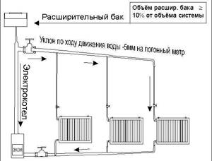
House heating scheme with natural circulation
It is important that in those places where CO pipes are laid horizontally, they must have a mandatory slope in the direction of coolant flow. This achieves the movement of water in the system without stagnation and the automatic removal of air from the system to its highest point, which is located in the expansion tank
It is made in one of three options: open, with a built-in air vent, or sealed.
Choosing an installation location
All installation requirements come down to two rules:
- The pump must ensure full circulation of the coolant in the circuit in compliance with the hydrodynamic operating mode;
- The orientation of the pump and the installation method are determined by its design and the manufacturer's requirements.
In the first case, this means that the pump must pump the coolant evenly throughout the entire circuit without creating problem areas or improper redistribution of the liquid. If we conditionally divide the heating system into an area with a boiler and its piping and a circuit with radiators, then the pump is installed strictly on the border.
It is not allowed to install it in the middle of the circuit so that part of the heat exchangers or other heating devices, storage tanks, etc. located between the pump and the main part of the circuit.
It would be a mistake to install, for example, in the middle of the circuit to increase the pressure on radiators farthest from the boiler. Often such measures are resorted to when the wiring or performance parameters of the main pump were initially calculated incorrectly and they try to correct the situation with the help of additional pumps.
However, in practice, this will lead to a failure in coolant circulation with the formation of reverse current or stagnation due to pressure imbalance at various points in the circuit.
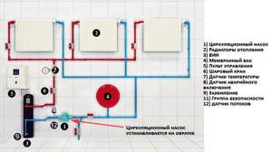
Pump installation diagram
At the same time, it is important to take into account the manufacturer’s installation requirements. The direction of movement of the coolant is always indicated on the pump body, determining the method of inclusion, and the instructions determine the available positions (vertically, horizontally, at permissible angles of inclination).
In general, the rotor should be positioned horizontally, and the power connection unit with terminals and automation should be located on the side or on top so that even if there is a leak, the coolant does not get on the contacts, causing a short circuit.
Installing the pump on the return or supply line does not matter if it is initially designed to work with the pumped medium at temperatures up to 100-110ºС. In addition to the above rules, you should only focus on ease of access to the installation site. So, in many cases, it is better to install a pump on the supply line located at the top, because it will be easier to access for maintenance and repair.
Recommendations for installing pumps
In order to ensure normal circulation of fluid in the heating system, you need to make the right choice of the place where the pump will be installed. A location in the water suction area should be identified where excess hydraulic pressure is always present.
Most often, the highest point of the pipeline is selected, from which the expansion tank rises to a height of approximately 80 cm. The use of this method is possible in a room with a high altitude. It is usually practiced to install an expansion tank in the attic, provided that it is insulated for the winter.
In the second case, the tube is transferred from the expansion tank and cuts into the return pipe instead of the supply pipe. The suction pipe of the pump is located near this place, so the most favorable conditions are created for forced circulation.
The third installation option is to insert the pump into the supply line, directly behind the point at which water flows from the expansion tank. The use of such a connection is possible if a particular model is resistant to high water temperatures.
Device operation
Despite the large amount of information, many find it difficult to understand where and how to properly install a circulation pump to ensure forced circulation of water in the home heating system.
You need to follow the instructions. Often this block is located on the return pipeline, which leads to the following situations:
- The temperature of the liquid in the supply is much higher, so the pump does not work.
- Hot water is less dense.
- The static pressure in the pipeline is higher, which facilitates the operation of the device.
Sometimes, when you get into a room where a boiler is installed that provides heating in the apartment, you can see that the system is based on return.
We can say that this is the only correct solution, even if you don’t know about the centrifugal device that can be installed in the outlet pipe.
In an emergency and as a result of an increase in pressure, a safety valve is activated, which releases steam from the boiler. If the action is not completed, the valve allows pressure to be released, resulting in an explosion of the boiler shell.
Experience shows that no more than 5 minutes after the start of the heating process, the safety valve is activated. If you install the device on the return pipeline, steam will not appear in it, and the time before an accident will increase to 20 minutes.
That is, if you install a check valve, you cannot prevent an explosion, but you can delay it in order to gain time to make a decision.
Where to put
It is recommended to install a circulation pump after the boiler, before the first branch, but on the supply or return pipeline it doesn’t matter. Modern units are made from materials that can withstand temperatures up to 100-115°C. There are few heating systems that work with a hotter coolant, so considerations of a more “comfortable” temperature are untenable, but if you feel safer, put it in the return line.
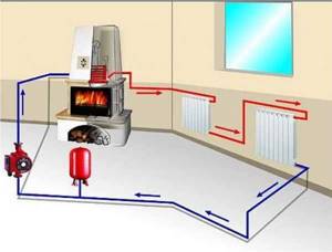
Can be installed in the return or direct pipeline after/before the boiler up to the first branch
There is no difference in hydraulics - the boiler, and the rest of the system; it makes absolutely no difference whether there is a pump in the supply or return branch. What matters is the correct installation, in terms of strapping, and the correct orientation of the rotor in space
Nothing else matters
There is one important point regarding the installation location. If the heating system has two separate branches - on the right and left wings of the house or on the first and second floor - it makes sense to install a separate unit on each, and not one common one - directly after the boiler. Moreover, the same rule remains on these branches: immediately after the boiler, before the first branch in this heating circuit. This will make it possible to set the required thermal conditions in each part of the house independently of the other, and also in two-story houses to save on heating. How? Due to the fact that the second floor is usually much warmer than the first floor and much less heat is required there. If there are two pumps in the branch that goes up, the speed of movement of the coolant is set much lower, and this allows you to burn less fuel, without compromising the comfort of living.
There are two types of heating systems - forced and natural circulation. Systems with forced circulation cannot work without a pump; systems with natural circulation work, but in this mode they have lower heat transfer. However, less heat is still much better than no heat at all, so in areas where electricity is often cut off, the system is designed as hydraulic (with natural circulation), and then a pump is installed into it. This gives high heating efficiency and reliability. It is clear that the installation of a circulation pump in these systems is different.
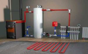
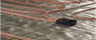
All heating systems with heated floors are forced - without a pump, the coolant will not pass through such large circuits
Forced circulation
Since a forced circulation heating system without a pump is inoperative, it is installed directly into the gap in the supply or return pipe (of your choice).
Most problems with the circulation pump arise due to the presence of mechanical impurities (sand, other abrasive particles) in the coolant. They can jam the impeller and stop the motor. Therefore, a mesh dirt filter must be placed in front of the unit.

Installing a circulation pump in a forced circulation system
It is also advisable to install ball valves on both sides. They will make it possible to replace or repair the device without draining the coolant from the system. Turn off the taps and remove the unit. Only that part of the water that was directly in this piece of the system is drained.
Natural circulation
The piping of the circulation pump in gravity systems has one significant difference - a bypass is required. This is a jumper that makes the system operational when the pump is not working. One ball shut-off valve is installed on the bypass, which is closed the entire time the pumping is running. In this mode, the system operates as forced.
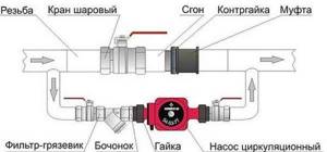
Installation diagram of a circulation pump in a system with natural circulation
When the electricity goes out or the unit fails, the valve on the jumper is opened, the valve leading to the pump is closed, and the system operates as a gravity system.
Installation features
There is one important point, without which the installation of the circulation pump will require rework: it is necessary to rotate the rotor so that it is directed horizontally. The second point is the direction of flow. There is an arrow on the body indicating which direction the coolant should flow. This is how you turn the unit so that the direction of movement of the coolant is “in the direction of the arrow”.
The pump itself can be installed both horizontally and vertically, just when selecting a model, make sure that it can work in both positions. And one more thing: with a vertical arrangement, the power (pressure created) drops by about 30%. This must be taken into account when choosing a model.
Features of installing a pump in a system with natural coolant circulation
In order to ensure the operation of the heating during a power outage, it is necessary to create a minimum hydraulic resistance in all sections of the circuit.
The normal movement of the thermal agent is hampered by any turns and height differences in the pipeline, the resistance of shut-off equipment and a decrease in the cross-section of the pipeline.
Therefore, when installing the circulation pump, the following requirements are observed:
- the insertion is performed without opening the main circuit, in parallel to it. The required pipeline diameter must be at least 32 mm, and the cross-section of the pipes for connecting the pump must be a quarter smaller;
- Shut-off valves are installed before and after the pump so that if the equipment malfunctions, it can be dismantled without the need to discharge the coolant;
- In the area between the pump taps, a ball valve is mounted, which is closed during the forced supply of coolant. Otherwise, it will circulate in a small circle between the pump insertion points.
A check valve installed instead of a ball valve will help automate the switching process in the absence of electricity.
The so-called bypass will be closed until the pump turns off and the pressure in front of the valve does not exceed the force of the operating spring.
The disadvantage of spring check valves is the additional resistance to fluid flow, so the best solution would be to install a ball-type device.
Two-pipe system with top wiring
The supply pipeline is laid under the ceiling, the return pipeline is laid along the floor. This explains the constantly high pressure in the system and allows the use of pipes of the same diameter even when forming a gravity-type structure. The expansion tank must be installed in the attic, making sure to insulate it, or placed between the ceiling - the lower part remains in the heated room, the upper part in the attic.
Experts recommend installing the upper line above the level of the window openings. In this case, it is possible to place the expansion tank under the ceiling, provided that the riser height is sufficient to ensure pressure in the system. The return pipe is laid out on the floor or lowered under it.
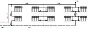
In the case of overhead wiring, the upper pipes remain visible, which does not improve the appearance of the room; also, some of the heat remains at the top and is not used to warm the rooms. You can run the pipes of the passing main under the radiators, and to ensure normal circulation, install a pump, which allows you to use small-diameter pipes.
In two-story private buildings, overhead wiring is considered effective and helps to achieve good heating of all rooms. The expansion tank is placed at the highest point, the boiler in the basement. This difference in height guarantees the efficiency of transportation of the coolant, the availability of connecting a tank to provide hot water supply - water circulation will ensure a constant flow of hot water to all appliances.
If you install a gas or non-volatile boiler in your house, the circuit becomes autonomous. To reduce costs, you should consider the option of combining a one- and two-pipe heating system. For example, make a warm (single-circuit) floor on the second floor, and equip a double-circuit structure on the first.
The advantages of the scheme are:
- coolant movement speed;
- maximum and even heating of rooms;
- eliminating the risk of air pockets.
The disadvantages include high consumption of components, insufficient energy to heat large rooms and difficulties with placing the expansion tank.
Forced circulation system elements
Forced circulation is a process that requires the installation of not only a pump, but also other required elements.
- These include:
expansion tank to compensate for the volume of coolant when temperature changes; safety group, including pressure gauge, thermometer, safety valve; radiators connected according to one of the wiring diagrams; Mayevsky taps or air separator; check valve; system fill and drain taps; coarse filter.
In addition, when using a solid fuel boiler as a heater. without the automatic fuel loading function, it is recommended to include a heat accumulator in the system - a storage tank of the required volume. This will equalize the temperature of the coolant and avoid its daily fluctuations.
Pipeline options
There are two types of two-pipe wiring: vertical and horizontal. Pipelines are usually installed vertically in multi-storey buildings. This scheme makes it possible to provide heating to each apartment, but at the same time there is a large consumption of materials.
Upper and lower wiring
The coolant is distributed according to the upper or lower principle. With top wiring, the supply pipeline passes under the ceiling and goes down to the radiator. The return pipe runs along the floor.
With this design, natural circulation of the coolant occurs well; thanks to the difference in heights, it manages to gain speed. But such wiring has not been widely used due to its external unattractiveness.
The diagram of a two-pipe heating system with bottom wiring is much more common. In it, the pipes are located at the bottom, but the supply, as a rule, passes slightly above the return. Moreover, pipelines are sometimes laid under the floor or in the basement, which is a big advantage of such a system.
This arrangement is suitable for schemes with forced movement of coolant, since with natural circulation the boiler must be at least 0.5 m below the radiators. Therefore, it is very difficult to install.
Counter and parallel movement of coolant
A two-pipe heating scheme in which hot water moves in different directions is called counter or dead-end. When the coolant moves through both pipelines in the same direction, it is called a passing system.
In such heating, when installing pipes, they often resort to the telescope principle, which makes adjustment easier. That is, when assembling a pipeline, sections of pipes are laid sequentially, gradually reducing their diameter. When the coolant moves in the opposite direction, thermal valves and needle valves are required for adjustment.
Fan connection diagram
A fan or beam circuit is used in multi-storey buildings to connect each apartment with the possibility of installing meters. To do this, a collector is installed on each floor with a pipe exiting to each apartment.
Moreover, only whole sections of pipes are used for wiring, that is, those without joints. Thermal metering devices are installed on pipelines. This allows each owner to control their heat energy consumption. When constructing a private house, this scheme is used for floor-by-floor piping.
To do this, a comb is installed in the boiler piping, from which each radiator is connected separately. This allows you to evenly distribute the coolant between the devices and reduce its losses from the heating system.
Purpose of the pump for heating
Cross-section of a circulation pump with a wet rotor
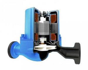
Previously, circulation pumps were used only in centralized heating systems, and for private housing construction the natural movement of the coolant caused by temperature differences was the norm.
Now forced circulation is used everywhere thanks to the emergence of compact and inexpensive models designed to service the heating networks of small houses and cottages.
The circulation pump is a component of the heating system. Designed to ensure forced movement of coolant through a closed circuit (circulation), as well as recirculation. To calculate the performance of a pump operating in a circulation system, only friction losses in the pipeline need to be taken into account. The height of the system (room) does not matter, since the liquid that is supplied by the pump to the supply pipe of the heating system also pushes the water in the opposite direction. Therefore, it is possible to use a relatively small pump power to circulate the coolant.
There are two types of such units - with a dry and wet rotor. Devices with a dry rotor have a high efficiency (about 80%), but are very noisy and require regular maintenance. Units with a wet rotor operate almost silently; with normal coolant quality, they can pump water without failure for more than 10 years. They have a lower efficiency (about 50%), but their characteristics are more than sufficient for heating any private home.
Options for piping in the system
The efficiency, economy and aesthetics of the heat supply system depend on the layout of heating devices and connecting pipes. The choice of wiring is determined based on the design features and area of the house.
Specifics of one-pipe and two-pipe schemes
Heated water flows to the radiators and back to the boiler in different ways. In a single-circuit system, the coolant is supplied through one large-diameter pipeline. The pipeline runs through all radiators.
Advantages of a single-pipe self-circulation system:
- minimal consumption of materials;
- ease of installation;
- limited number of pipes inside the living space.
The main disadvantage of a scheme with one pipe performing supply and return duties is the uneven heating of the heating radiators. The heating intensity and heat transfer of the batteries decreases as they move away from the boiler.
With a long wiring chain and a large number of radiators, the last battery may turn out to be completely ineffective. “Hot” heating devices are recommended to be installed in north-facing rooms, children’s rooms and bedrooms
The two-pipe heating scheme is confidently gaining ground. Radiators connect the return and supply pipelines. Local rings form between the batteries and the heat source.
- all heating devices heat up evenly;
- the ability to adjust the heating of each radiator separately;
- reliability of operation of the circuit.
A dual-circuit system requires large investments and labor costs. It will be more difficult to install two lines of communications along building structures.
The two-pipe system is easily balanced, ensuring the supply of coolant at the same temperature to all heating devices. Rooms are heated evenly
Upper and lower coolant supply
Depending on the location of the main line supplying hot coolant, a distinction is made between upper and lower connections.
In open heating systems with overhead wiring, there is no need to use air exhaust devices. Its excess is discharged through the surface of the expansion tank communicating with the atmosphere
With overhead distribution, warm water rises through the main riser and is transferred through distribution pipelines to the radiators. The installation of such a heating system is advisable in one- and two-story cottages and private houses.
A heat supply system with bottom wiring is quite practical. The supply pipe is located at the bottom, next to the return pipe. Coolant movement in the direction from bottom to top. The water, having passed through the radiators, is directed through the return pipeline to the heating boiler. The batteries are equipped with Mayevsky valves to remove air from the line.
In heating systems with bottom wiring, it becomes necessary to use air exhaust devices, the simplest of which is the Mayevsky tap
Vertical and horizontal risers
Based on the type of position of the main risers, a distinction is made between vertical and horizontal pipeline routing methods. In the first option, radiators on all floors are connected to vertical risers.
Vertical wiring is used when arranging houses of two, three or more floors with an attic space, within which a pipeline can be laid and insulated
Features of “vertical” systems:
- no air pockets;
- suitable for heating high-rise buildings;
- floor connection to the riser;
- difficulties in installing apartment heat meters in multi-storey buildings.
Horizontal wiring involves connecting radiators on one floor to a single riser. The advantage of the scheme is that the device uses fewer pipes and installation costs are lower.
Horizontal risers are usually used in one- and two-story premises. The arrangement of the system is relevant in panel-frame houses and residential buildings without walls
At what speed should the pump in the heating system operate?
The purpose of forced circulation is to effectively heat the house through the reliable delivery of heat to all consumers of the system, right up to the furthest radiator.
To do this, the pumping unit must develop the required pressure (otherwise known as pressure), which is ideally calculated by design engineers based on the hydraulic resistance of the pipeline network.
Most household pumps have from 3 to 7 rotor speeds, due to which the performance and pressure generated can be increased or decreased.
In order not to torment you with hydraulic calculations, we offer the following method for selecting the optimal speed:
- Find a laser surface thermometer (pyrometer). Put the heating system into operating mode.
- Measure the surface temperature of the pipe at the inlet and outlet of the boiler.
- If the temperature difference is more than 20 °C, increase the rotor speed. After 30 minutes, repeat the measurement.
- When the temperature difference is less than 10 °C, the water flow rate must be reduced. The goal is to achieve a delta between supply and return of about 15 °C.
Advice. Do not switch the pump to a different circulation speed “on the fly”. Disconnect it from the network, move the regulator to a different position, and then put it back into operation.
You can do without a pyrometer when thermometers are installed on the supply and return lines. If the adjustment limits do not allow you to enter the range of 10-20 °C temperature difference, your system is not working efficiently due to an incorrectly selected circulation pump.
Too cold return water increases the load on the boiler and increases fuel consumption. Water that is too hot means that it flows too quickly and does not have time to transfer heat to the heating devices.
Advantages
A system equipped with a circulation pump does not have these disadvantages. It is perfect for heating rooms ranging from 200 to 800 m2. Its advantages include:
- no requirements for the configuration of the heating circuit - for coolant circulation there is no need to create narrow places in the pipeline, install pipes at an angle and use other technical techniques;
- rapid acceleration of the liquid - circulation of heated water in the circuit begins immediately after turning on the pump. As a result, the rooms of a private house warm up to the desired temperature in just a few minutes;
- high efficiency - thanks to the rapid circulation of the coolant, heat losses are reduced. The problem is solved when one of the rooms warms up more than the others. Due to this, fuel is consumed more economically;
- reliability of operation - the simple design of the pump eliminates the occurrence of accidental breakdowns.
If you plan to equip a system with natural circulation with a pump, its design remains virtually unchanged.
All you need to do is install the pump itself, and also move the expansion tank from the water supply circuit to the circuit through which it returns to the boiler.
Useful tips
Circulation pumps are divided into 2 groups, according to the specific location of the rotor - “wet” and “dry”. What is the difference? Without going into the specifics of engineering solutions, it is enough to just note the pros and cons of each modification.
With a “dry” rotor. Higher efficiency. But there are also disadvantages - increased “noise”, the need for regular maintenance (primarily lubrication of seals) and special requirements for operating conditions.
Such circulation pumps must be installed in separate, absolutely clean rooms. The explanation is simple - the slightest dust leads to a decrease in their efficiency or breakdown.
Recommendation - it is advisable to purchase a “dry” pump if there is no analogue in the boiler itself, and the product is the only device that ensures water circulation through the pipes of the heating system.
With a “wet” rotor. As a rule, these pumps are installed more often.
The fact is that all modern household heating boilers are initially equipped with such a device (located under the casing of the unit), and the newly installed one serves only as an additional element that ensures better coolant circulation.
For example, when choosing the wrong heat generator model, when increasing the length of the heating circuit, when installing radiators not provided for in the primary circuit.
The disadvantage of such a pump is low efficiency. But taking into account that it is not the only one in the system, this drawback is leveled out, since it does not particularly affect the heating efficiency. An additional advantage is that no maintenance is required.
Such pumps function properly until their service life is completely exhausted, provided that the rules for their installation are followed. Recommendation - if your household boiler already has its own pump, then you can safely choose a product with a “wet” rotor.
Open and closed heating system
If an open type expansion tank is installed, then the system is called open. In its simplest form, it is some kind of container (saucepan, small plastic barrel, etc.) to which the following elements are connected:
- small diameter connecting pipe;
- a level control device (float), which opens/closes the make-up valve when the amount of coolant drops below a critical level (in the figure below it works on the principle of a toilet flush cistern);
- air release device (if the tank without a lid is not necessary);
- drain hose or circuit for removing excess coolant if its level exceeds the maximum.

One of the open type expansion tanks
Today, open systems are made less and less often, and all because a large amount of oxygen is constantly present in it, which is an active oxidizer and accelerates corrosion processes. When using this type, heat exchangers fail much faster, pipes, pumps and other elements are destroyed. In addition, due to evaporation, you have to constantly monitor the coolant level and periodically add it. Another drawback is that it is not recommended to use antifreeze in open systems due to the fact that they evaporate, that is, they harm the environment, and also change their composition (the concentration increases). That’s why closed systems are becoming more and more popular - they exclude the supply of oxygen, and the oxidation of elements occurs much slower because they are considered better.
A membrane-type tank is installed in closed heating systems
In closed systems, membrane-type tanks are installed. In them, the sealed container is divided into two parts by an elastic membrane. At the bottom there is a coolant, and the upper part is filled with gas - ordinary air or nitrogen. When the pressure is low, the tank is either empty or contains a small amount of liquid. As the pressure increases, an increasing amount of coolant is forced into it, which compresses the gas contained in the upper part. To prevent the device from bursting if the threshold value is exceeded, an air valve is installed in the upper part of the tank, which is activated at a certain pressure, releasing part of the gas and equalizing the pressure.
Rules for connecting to power supply
The circulation pump is powered. The connection is standard. It is recommended to install a separate power supply line with a surge protector.
To connect, you need to prepare 3 wires - phase, neutral and ground. You can choose any of the connection methods:
- through a differential machine device;
- connection to the network together with an uninterruptible power supply;
- power supply to the pump from the boiler automation system;
- with thermostat regulation.
Many people wonder why complicate things, because connecting the pump can be done by connecting a plug to a wire.
This is how the pumping device is plugged into a regular outlet. However, experts do not recommend using this method due to the risk of unforeseen situations: there is no grounding and a safety device.
The first option is not difficult to assemble yourself. It is necessary to install an 8 A differential circuit breaker. The wire cross-section is selected based on the device rating.
In the standard scheme, the power supply is carried out to the upper sockets - they are marked with odd numbers, the load - to the lower ones (even numbers). Both phase and neutral will be connected to the machine, so the connectors for the latter are designated by the letter N.
To automate the process of stopping the circulation of the coolant when cooling to a certain temperature, an electrical circuit is used to connect the pump and thermostat.
The second is mounted in the supply line. At the moment when the water temperature drops to the specified value, the device disconnects the electrical supply circuit.
There are no difficulties in supplying electricity through an uninterruptible power supply; it has special connectors for this. A heat generator is also connected to them when there is a need to provide electricity.
If you choose the method of connecting the pump to the boiler control panel or automation, you will need good knowledge of the power supply system or the help of a professional.
Heating system with a complex of lines
In a scheme divided into several separate heating lines that heat different floors or sides of the house, each branch has its own pump installed. When installing a specific device, you can adjust the desired operating mode. Since heat tends to rise upward, it will always be warmer on the top floor, so you can reduce the circulating speed of the coolant. The insertion of the device is carried out in the same way (after the heat generator to the first branch). When installing two devices in a two-story mansion, much less coolant will be consumed for heating the second floor.
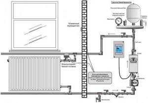
One-pipe system versus two-pipe
The main distinguishing feature of a single-pipe design is one pipe to which the heating device is connected. Radiators are connected in series. The coolant cools down in each of them and approaches subsequent devices with a lower temperature. Thus, the last batteries in the chain are much colder than the first. The advantage of the system is the relatively low cost of components and installation. However, there are also significant drawbacks.
The first is the inability to regulate the temperature of the radiators. You can neither reduce nor increase heat transfer, nor can you disconnect the battery from the system. However, when installing devices using a special jumper called a bypass, it will be possible to turn off the radiator if necessary. But indirect heating of the room using supply pipes and riser will continue.
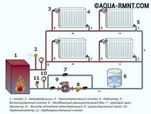
A single-pipe heating system does not imply the possibility of regulating the temperature of the coolant in the radiators; in addition, less heated water flows into each subsequent heating device in the chain
The second significant drawback is the temperature difference between heating devices connected in series. To level it out as much as possible, you can select radiators of different sizes. In this case, the smallest one should be the first, and the area of all subsequent ones gradually increases. However, the appearance of the premises in which the system will be located may suffer from such diversity.
Two-pipe systems involve connecting a supply and discharge pipe to each radiator. Thus, the coolant cooled in the equipment is diverted to the boiler and does not flow into the next device. This allows water to be supplied to the radiators at approximately the same temperature. The system does not have the disadvantages of single-pipe structures. It can use pipes with a smaller diameter and connections of smaller standard sizes, which makes the structure more aesthetically pleasing and allows it to be used for hidden installation, for example, in a floor screed.
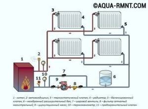
A distinctive feature of the two-pipe system: each radiator has an inlet and outlet line, which allows maintaining the same temperature of the coolant at the approach to all devices
The parallel connection of two-pipe radiators is very convenient. When installed, a tap is mounted on each device, making it possible to regulate the temperature of the equipment. If necessary, you can use it to disconnect the battery from the system and replace or repair it. There are models of thermostatic regulators that allow you to regulate the room temperature automatically. The main disadvantage of two-pipe structures is the larger number of pipes required for installation. This makes the system more expensive and more difficult to install.
Heating systems with pump circulation
As has already been mentioned several times, the main disadvantage of a heating system with natural circulation of coolant is the low circulation pressure (especially in an apartment system) and, as a result, the increased diameter of the pipes. It is enough to make a slight mistake with the choice of pipe diameters and the coolant is already “squeezed” and cannot overcome the hydraulic resistance. You can “unclamp” the system without any significant alterations: turn on the circulation pump (Fig. 12) and move the expansion tank from the supply to the return. It should be noted that moving the expander to the return line is not always necessary. When simply altering a simple heating system, for example, an apartment heating system, the tank can be left where it was. With proper reconstruction or installation of a new system, the tank is moved to the return line and replaced from open to closed.
rice. 12. Circulation pump
What power should the circulation pump have, how and where should it be installed?
Circulation pumps for household heating systems have low electricity consumption - about 60-100 watts, that is, like a regular light bulb, they do not lift water, but only help it overcome local resistance in the pipes. These pumps can be compared to the propeller of a ship: the propeller pushes water and ensures the movement of the ship, but at the same time the water in the ocean does not decrease or increase, that is, the overall balance of water remains the same. The circulation pump attached to the pipeline pushes water, but no matter how much it pushes it out, the same amount of water comes to it from the other side, that is, fears that the pump will push the coolant through the open expander are in vain: the heating system is a closed circuit and the quantity there is constant water in it. In addition to circulation pumps, centralized systems can include booster pumps that increase pressure and are capable of lifting water; they should actually be called pumps, but circulation pumps, translated into a generally understandable language, can hardly be called pumps - so... fans. No matter how much an ordinary household fan drives air around the apartment, all it can do is create a breeze (air circulation), but it is not able to change the atmospheric pressure even in a tightly closed room.
As a result of the use of a circulation pump, the radius of action of the heating system is significantly increased, the diameters of pipelines are reduced and the possibility of connecting systems to boilers with increased coolant parameters is created. To ensure silent operation of a water heating system with pump circulation, the speed of movement of the coolant should not exceed: in pipelines laid in the main premises of residential buildings, with nominal pipe diameters of 10, 15 and 20 mm or more, respectively, 1.5; 1.2 and 1 m/s; in pipelines laid in auxiliary premises of residential buildings - 1.5 m/s; in pipelines laid in auxiliary buildings - 2 m/s.
To ensure the noiselessness of the system and its delivery of the required volume of coolant, it is necessary to make a small calculation. We already know how to roughly determine the required boiler power (in kilowatts), based on the area of the heated premises. The optimal water flow rate passing through the boiler, recommended by many boiler equipment manufacturers, is calculated using a simple empirical formula: Q=P, where Q is the coolant flow rate through the boiler, l/min; P - boiler power, kW. For example, for a 30 kW boiler, the water flow is approximately 30 l/min. To determine the coolant flow rate in any section of the circulation ring, we use the same formula, knowing the power of the radiators installed in this section, for example, we calculate the water flow rate for radiators installed in one room. Let's assume that the power of the radiators is 6 kW, which means that the coolant flow rate will be approximately 6 l/min.
Based on water flow, we determine the diameters of the pipelines (Table 1). These values correspond to the practically accepted correspondence between pipe diameters and the flow rate of coolant flowing through them at a speed of no more than 1.5 meters per second.
Table 1
Correspondence of pipeline diameters with coolant flow
| Consumption, l/min | 5,7 | 15 | 30 | 53 | 83 | 170 | 320 |
| Diameter, inches | 1/2 | 3/4 | 1 | 1¼ | 1½ | 2 | 2½ |
Next, we determine the power of the circulation pump. For every 10 meters of circulation ring length, 0.6 meters of pump pressure is required. For example, if the total length of the pipeline ring is 90 meters, the pump head should be 5.4 meters. We go to the store (or select it from a catalog) and purchase a pump with a pressure that suits us. If pipes of smaller diameters than those recommended in the previous paragraph are used, the pump power should be increased, since the thinner the pipes, the greater their hydraulic resistance. And accordingly, when using pipes of large diameters, the pump power can be reduced.
In order to ensure constant circulation of water in heating systems, it is advisable to install at least two circulation pumps, one of which is working, the other (on the bypass) is backup. Or one pump is installed on the system, and the other is kept in a secluded place, in case of a quick replacement if the first one breaks down.
It should be noted that the calculation of the heating system given here is extremely primitive and does not take into account many factors and features of the individual heating system. If you are building a cottage with a complex heating system architecture, then it is necessary to make accurate calculations. This can only be done by heating engineers. It is extremely unreasonable to build a multi-million dollar structure without as-built documentation - a project that takes into account all the features of the construction.
The circulation pump in the heating system is filled with water and experiences equal (if the water is not heated) hydrostatic pressure on both sides - from the inlet (suction) and outlet (discharge) pipes connected to the heat pipes. Modern circulation pumps, made with water-lubricated bearings, can be placed on both the supply and return pipelines, but most often they are installed on the return. Initially, this was due to a purely technical reason: when placed in colder water, the service life of the bearings, rotor and stuffing box through which the pump shaft passes increased. And now they are put on the return line rather out of habit, since from the point of view of creating artificial circulation of water in a closed circuit, the location of the circulation pump is indifferent. Although placing them on the supply pipeline, where hydrostatic pressure is usually lower, is more rational. For example, an expansion tank is installed in your system at a height of 10 m from the boiler, which means it creates a static pressure of 10 m of water column, but this statement is true only for the lower pipeline; in the upper one the pressure will be less, since the water column here will be smaller. Wherever we place the pump, it will be subject to the same pressure on both sides, even if it is placed on a vertical main supply or return riser, the pressure difference between the two pipes of the pump will be small, since the pumps are small in size.
Don't miss: Coating welding electrodes.
However, everything is not so simple. A pump operating in a closed circuit of the heating system increases circulation by pumping water into the heat pipe on one side and sucking it in on the other. The water level in the expansion tank will not change when the circulation pump is started, since a uniformly operating pump only ensures circulation with a constant amount of water. Since under these conditions (uniformity of pump action and constant volume of water in the system) the water level in the expansion tank remains unchanged, it does not matter whether the pump is running or not, the hydrostatic pressure at the point where the expander connects to the system pipes will be constant. This point is called neutral, since the circulation pressure developed by the pump does not in any way affect the static pressure created by the expansion tank. In other words, the pressure of the circulation pump at this point is zero.
In any closed hydraulic system, the circulation pump uses the expansion tank as a reference point at which the pressure developed by the pump changes its sign: up to this point the pump, creating compression, pumps water, after it, causing a vacuum, it sucks in water. All heat pipes of the system from the pump to the point of constant pressure (counting in the direction of water movement) will belong to the pump discharge zone. All heat pipes after this point go to the suction zone. In other words, if the circulation pump is inserted into the pipeline immediately after the expansion tank connection point, it will suck water from the tank and pump it into the system; if the pump is installed before the tank connection point, the pump will pump water out of the system and pump it into the tank.
So what, what difference does it make to us whether the pump pumps water out of the tank or pumps it into it, as long as it rotates it through the system. But there is a significant difference: the static pressure created by the expansion tank interferes with the operation of the system. In pipelines located in the pump discharge area, an increase in hydrostatic pressure compared to the water pressure at rest must be taken into account. On the contrary, in pipelines located in the suction zone of the pump, it is necessary to take into account the decrease in pressure, and it is possible that the hydrostatic pressure will not only drop to atmospheric pressure, but even a vacuum may occur. That is, as a result of the pressure difference in the system, there is a danger of suction or release of air or boiling of the coolant.
In order to avoid disruption of water circulation due to its boiling or air suction, when designing and hydraulically calculating water heating systems, the following rule must be observed: in the suction zone at any point in the heating system pipelines, hydrostatic pressure must remain excessive when the pump operates. There are four possible ways to implement this rule (Fig. 13).
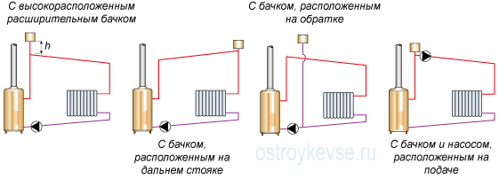
rice. 13. Schematic diagrams of heating systems with pump circulation and an open expansion tank
1. Raising the expansion tank to a sufficient height (usually at least 80 cm). This is a fairly simple method for reconstructing systems with natural circulation into a pump circulation, but it requires a significant attic space and careful insulation of the expansion tank. 2. Moving the expansion tank to the most dangerous upper point in order to include the upper line in the discharge zone. A clarification is necessary here. In new heating systems, supply pipelines with pump circulation are made with slopes not from the boiler, but towards the boiler, so that air bubbles move along with the water, since the driving force of the circulation pump will not allow them to float “against the flow”, as was the case in systems with natural circulation. Therefore, the highest point of the system is not at the main riser, but at the most distant one. For the reconstruction of an old system with natural circulation to the pumping station, this method is quite labor-intensive, since it requires alteration of the pipelines, and for creating a new system, it is not justified, since other, more successful options are possible. 3. Connect the expansion tank pipe near the suction pipe of the circulation pump. In other words, if we reconstruct an old system with natural circulation, then we simply cut off the tank from the supply line and connect it to the return line behind the circulation pump and thereby create the most favorable conditions for the pump. 4. We depart from the usual scheme of placing the pump on the return line and plug it into the supply line immediately after the expansion tank connection point. When reconstructing a system with natural circulation, this is the simplest method: we simply cut the pump into the supply pipe without altering anything else. However, you need to be very careful when choosing a pump; after all, we place it in unfavorable conditions of high temperatures. The pump will have to serve for a long time and reliably, and only reputable manufacturers can guarantee this.
The modern market for plumbing and heating fittings makes it possible to replace open expansion tanks with closed ones. In a closed tank, there is no contact of the system fluid with air: the coolant does not evaporate and is not enriched with oxygen. This reduces heat and water losses and reduces internal corrosion of heating devices. Liquid will never spill out of a closed tank.
A closed-type expansion tank (“expanzomat”) is a spherical or oval-shaped capsule, divided inside by a sealed membrane into two parts: air and liquid. A nitrogen-containing mixture is pumped into the air part of the housing under a certain pressure. Before the heating system is filled with water, the pressure of the gas mixture inside the tank tightly presses the diaphragm to the water part of the tank. Heating the water leads to the creation of working pressure and an increase in the volume of coolant - the membrane bends towards the gas part of the tank. At maximum operating pressure and maximum increase in water volume, the water part of the tank is filled and the gas mixture is compressed to its maximum. If the pressure continues to rise and the volume of coolant continues to increase, then the safety valve is activated, releasing water (Fig. 14).
Don't miss: Heating system safety group
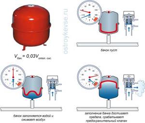
rice. 14. Membrane type expansion tank
The volume of the tank is selected such that its useful volume is not less than the volume of thermal expansion of the coolant, and the preliminary air pressure in the gas part of the tank is made equal to the static pressure of the coolant column in the system. This selection of gas mixture pressure allows you to keep the membrane in an equilibrium (not tense) position when the heating system is filled but not turned on.
A closed tank can be placed at any point in the system, but, as a rule, it is installed next to the boiler, since the temperature of the liquid at the location where the expansion tank is installed should be as low as possible. And we already know that it is best to install the circulation pump immediately behind the expander, where the most favorable conditions are created for it (and for the heating system as a whole) (Fig. 15).
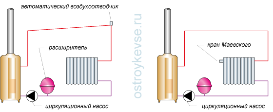
rice. 15. Schematic diagrams of heating systems with pump circulation and a closed expansion tank
However, with such a heating system design, we are faced with two problems: air removal and increased pressure on the boiler.
If in systems with open expansion tanks the air was removed through the expander countercurrently (in systems with natural circulation) or along the way (in systems with pump circulation), then this does not happen with closed tanks. The system is completely closed and there is simply nowhere for air to escape. To remove air pockets, automatic air bleeders are installed at the top of the pipeline - devices equipped with floats and shut-off valves. As the pressure increases, the valve is activated and releases air into the atmosphere. Or Mayevsky taps are installed on each heating radiator. This part, installed on heating devices, allows you to bleed the air plug directly from the radiators. The Mayevsky tap is included with some radiator models, but is often offered separately.
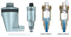
rice. 16. Automatic air vent
The principle of operation of air vents (Fig. 16) is that in the absence of air, a float inside the device keeps the exhaust valve closed. As air collects in the float chamber, the water level inside the air vent drops. The float lowers and the outlet valve opens, through which air is released into the atmosphere. After the air is released, the water level in the air vent rises and the float floats, which leads to the closure of the exhaust valve. The process continues until air re-collects in the float chamber and lowers the water level, lowering the float. Automatic air vents are manufactured in different designs, shapes and sizes and can be installed both on the main pipeline and directly (L-shaped) on radiators.
The Mayevsky valve, in contrast to an automatic air vent, is, in general, an ordinary plug with an air vent channel and a conical screw screwed into it: by turning the screw, the channel is released and the air comes out. Turning the screw closes the channel. There are also air vents in which, instead of a conical screw, a metal ball is used to block the air discharge channel.
Instead of automatic air vents and Mayevsky taps, an air separator can be included in the heating system. This device is based on the application of Henry's law. The air present in heating systems is partly in dissolved form and partly in the form of microbubbles. As water (along with air) passes through the system, it enters areas of different temperatures and pressures. According to Henry's Law, in some areas air will be released from the water, and in others it will dissolve in it. In the boiler, the coolant is heated to a high temperature, so it is in it that the largest amount of air in the form of tiny bubbles will be released from the air-containing water. If they are not removed immediately, they will dissolve in other places in the system where the temperature is lower. If you remove microbubbles immediately after the boiler, then at the outlet of the separator you will get deaerated water, which will absorb air in different places in the system. This effect is used to absorb air in the system and release it to the atmosphere through a combination of boiler and air separator. The process continues continuously until air is completely removed from the system.
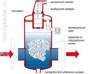
rice. 17. Air separator
The operation of the air separator (Fig. 17) is based on the principle of fusion of microbubbles. In practical terms, this means that small air bubbles stick to the surface of special rings and gather together, forming large bubbles that can separate and float into the air chamber of the separator. When liquid flow passes through the rings, it diverges in many different directions, and the design of the rings is such that all liquid passing through them comes into contact with their surface, allowing microbubbles to adhere and coalesce.
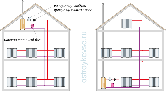
rice. 18. Schematic diagrams of heating systems with pump circulation, a closed expansion tank and an air separator
Now let's take a little break from the air and go back to the circulation pump. In heating systems with long pipelines and, as a result, with large hydraulic losses, quite powerful circulation pumps are often required, creating a pressure at the discharge pipe greater than that for which the heating boiler is designed. In other words, when placing the pump on the return line directly in front of the boiler, connections in the boiler heat exchanger may leak. To prevent this from happening, powerful circulation pumps are installed not in front of the boiler, but behind it - on the supply pipeline. And the question immediately arises: where to place the air separator, behind the pump or in front of it? Leading manufacturers of heating systems have resolved this issue and propose installing a separator in front of the pump (Fig. 18) to protect it from damage by air bubbles.
Now let’s look at heating systems with pump circulation in more detail.
Additional equipment
Regardless of the type of system where heat is produced by the boiler alone, it will be sufficient to install one pumping device. With a complex heat supply scheme, it is possible to use secondary devices. The need for this arises in cases where:
- heating a building requires more than one boiler;
- the piping scheme is equipped with a buffer capacity;
- the heating system branches into several lines;
- hydraulic separators are used;
- the length of the heating main exceeds 80 meters;
- need to organize heated floors.
In order to properly connect a number of boilers operating on different fuels, it is necessary to install additional pumps. For a circuit with a thermal accumulator, secondary pumping devices are also required. The main line, in this case, is built from two circuits: boiler and heating.
A much more complex system is implemented in 2- and 3-story buildings. Branching a pipeline into several branches requires the use of two or more pumps. Each of them supplies heat to its floor to specific heating devices. If the house is designed with heated floors, then two pumps are installed. One of them will be responsible for the coolant, designed to maintain a temperature of 30-40 degrees. Celsius.

